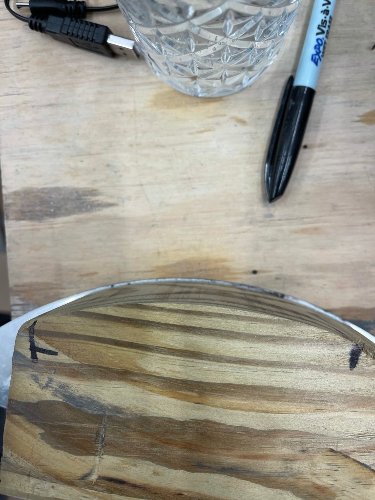
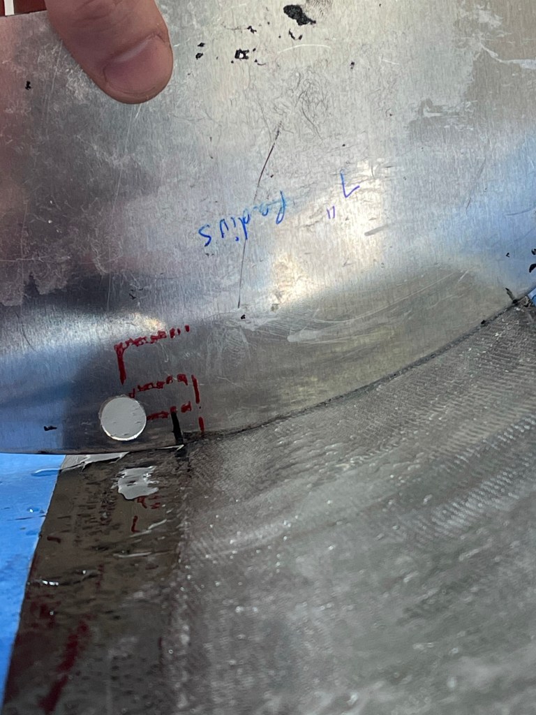
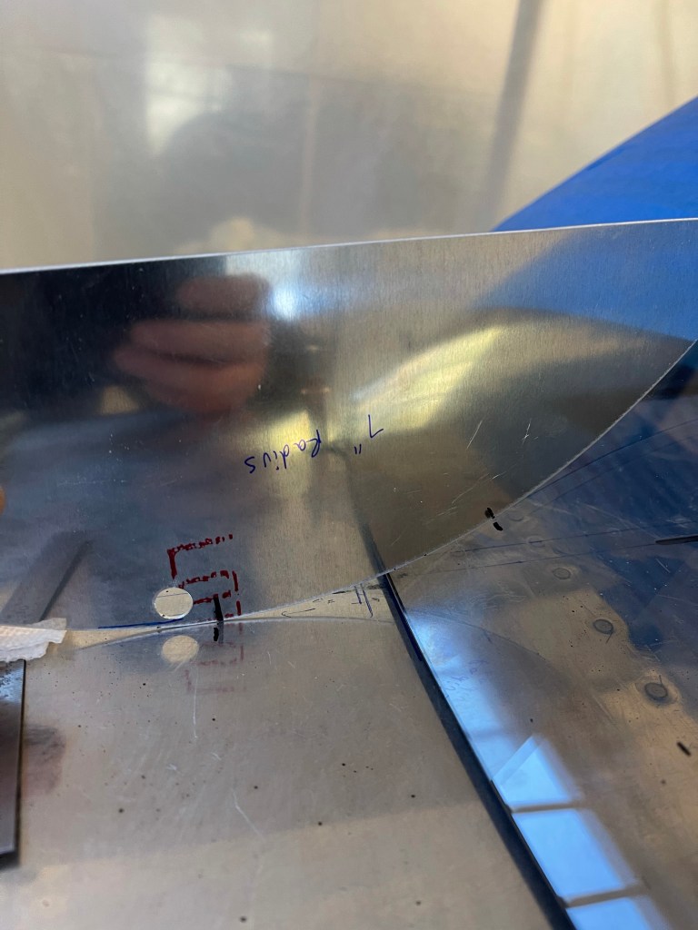
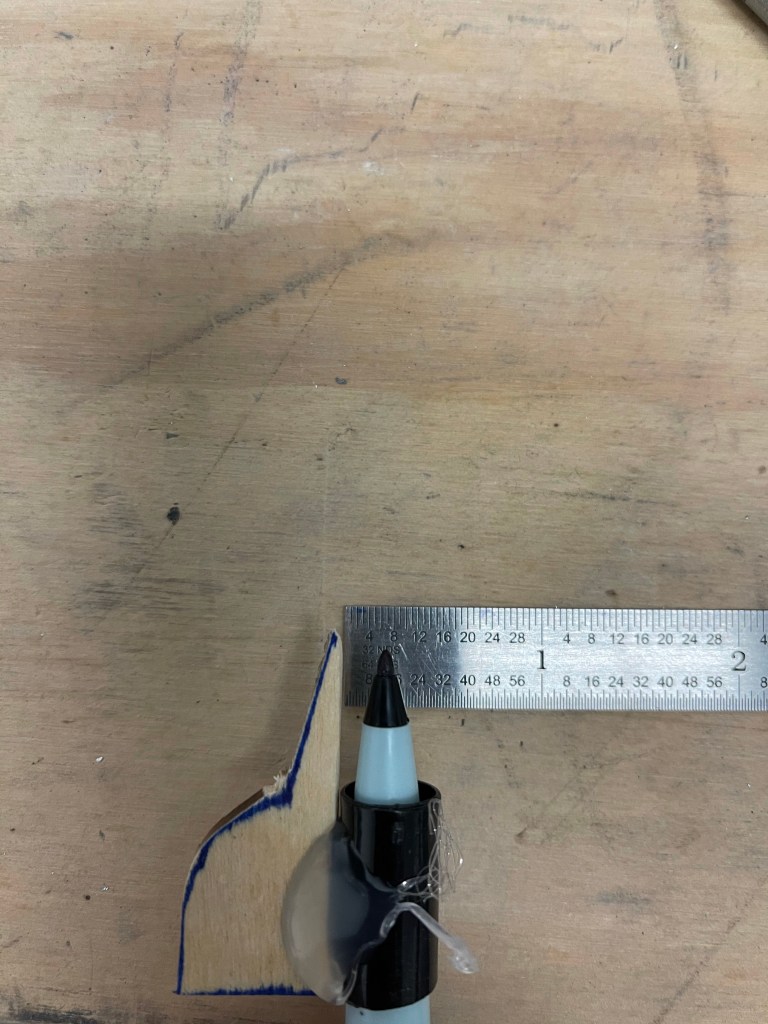
First up while the layup was curing was to make a 7″ radius sanding tool. I had a 4×4 piece of lumber that I ripped to be the same length as the width of the layup.. Then I marked the radius from the metal tool I had made onto the side. It took me a couple of tries to figure out how exactly to mark it (as you can see) in order to have it end up being correct. I then cut it out on my bandsaw and compared to me template.
Marking the 7″ radiusComparing the result to the template.
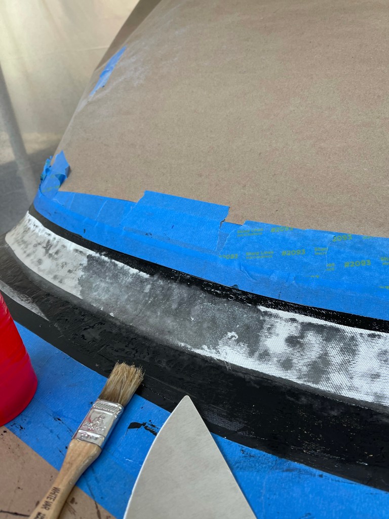
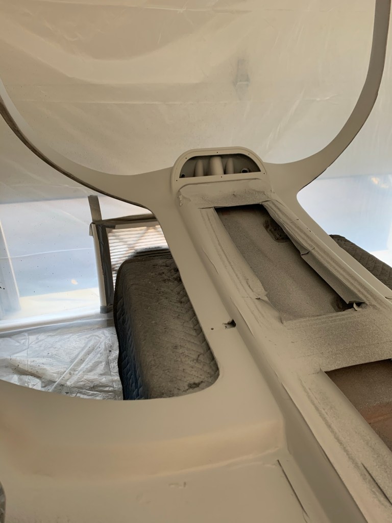
I used this tool with 50 grit sandpaper glued on initially to sand the shape across the front. The shape is mostly flat as you approach the sides where the leading edge of the door is. In between the front center and the extreme edges, the contour continually changes making it hard to sand. I ended up using the 7″ radius block I had made angled at about 45 degrees and occasionally used circular motions as well. I feel like it worked well.
The idea here is there are 2 layers of electrical tape on the windscreen and the metal fuselage. You continue to sand until you’re just scuffing the surface of the top layer of tape. Once that happens, you take the top-most layer of tape off and continue sanding with finer grit until you start scuffing the bottom layer. This will help create a feathered edge onto the mating surfaces. Once I was done with sanding (several days worth.. ) I started to fill some low spots with epoxy and micro.
Getting closer
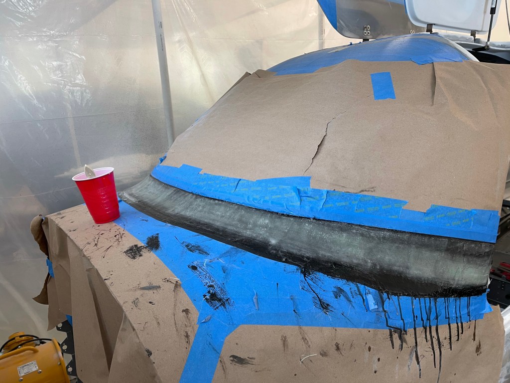
Once satisfied with the overall shape, you start to put a skim coat of epoxy down to seal up the final part and fill any pinholes. A very similar process to what I used to finish the overhead console. I used a squeegee and a foam roller to get good coverage and left it to cure overnight.
Closeup of the final shapelittle bumps of epoxy will be sanded out once cured.
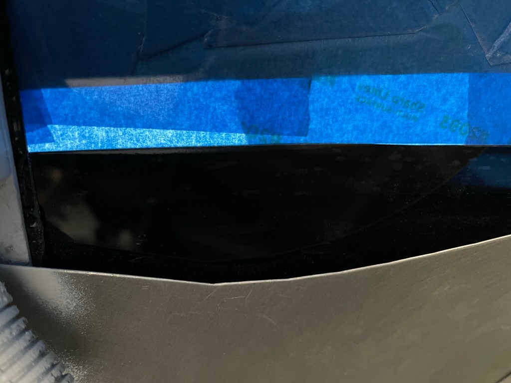
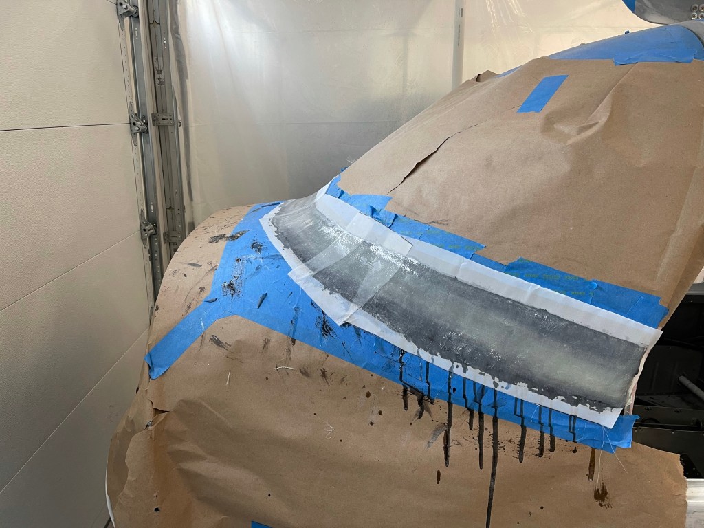
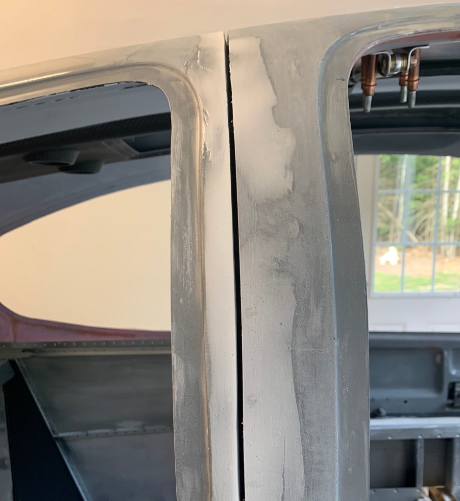
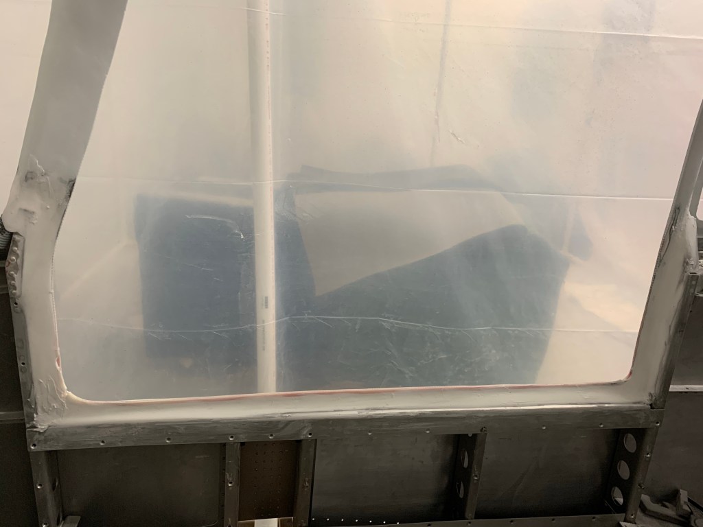
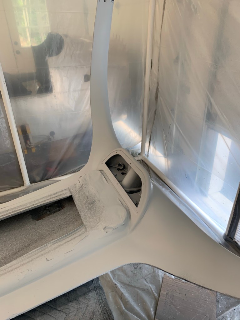
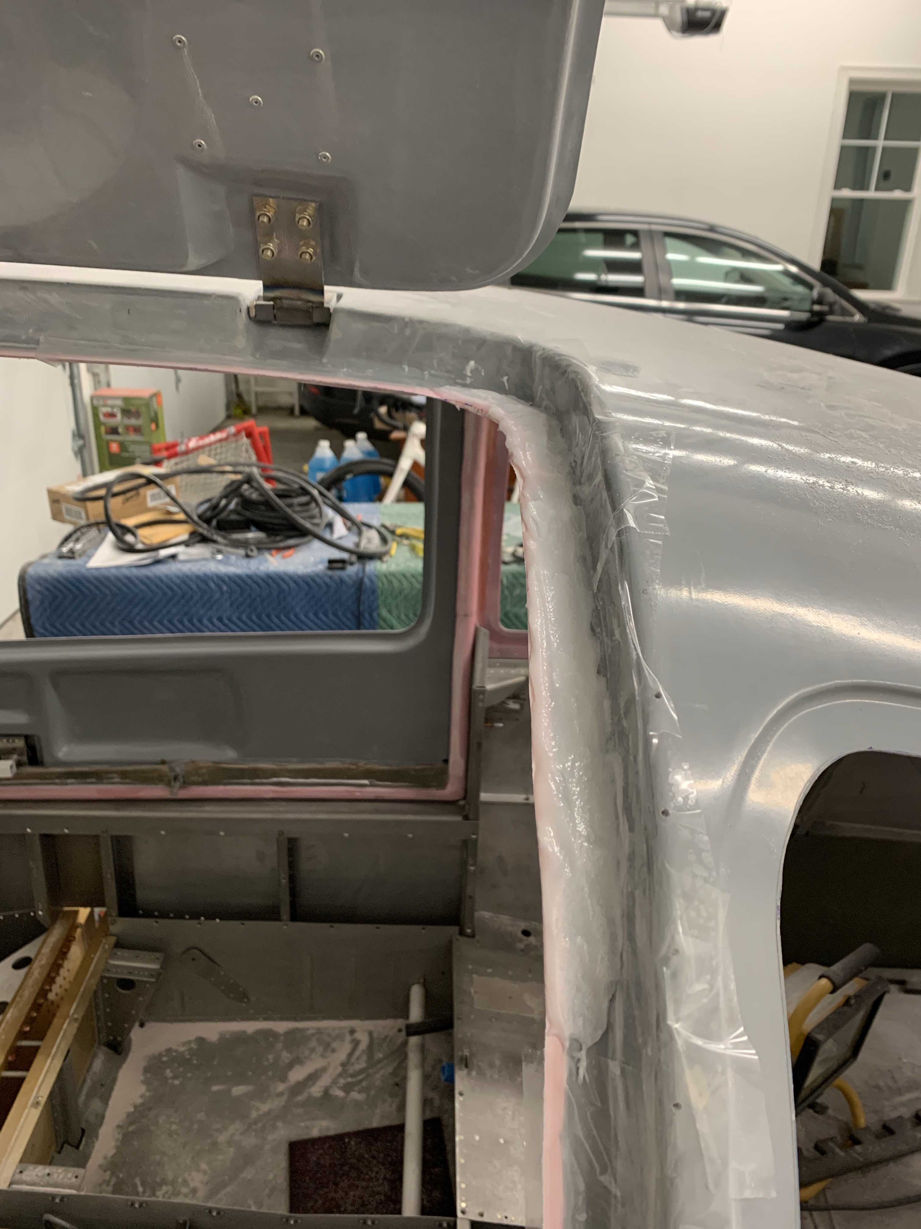
Once done, I pulled off the tape to see the result.. Here is a shot along the left side.
A view from the inside where you can see the really nice black line all the way around the base of the windscreen. Very happy with how this turned out!
I still have some touchup to do along the feathered edges and then I will be using some high-build primer to paint the fairing. I’ll leave it that way until paint.
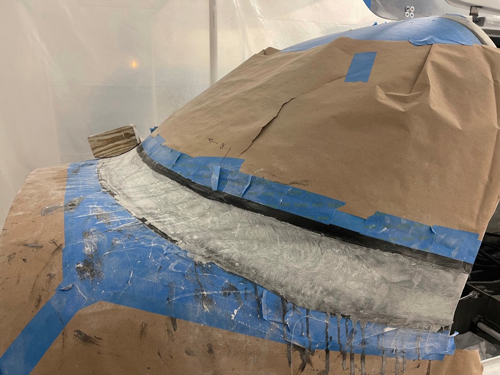
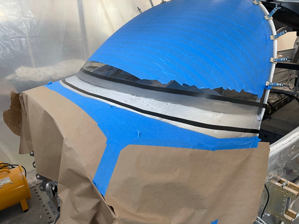
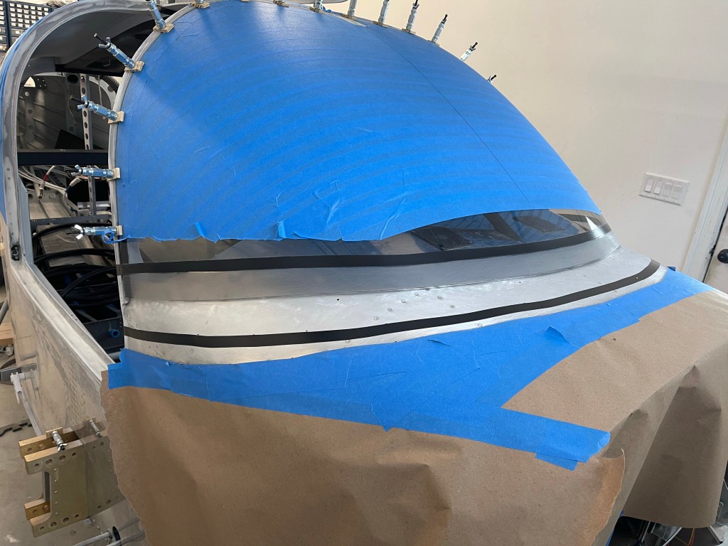
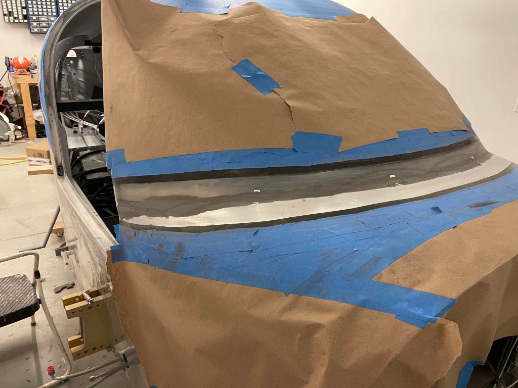
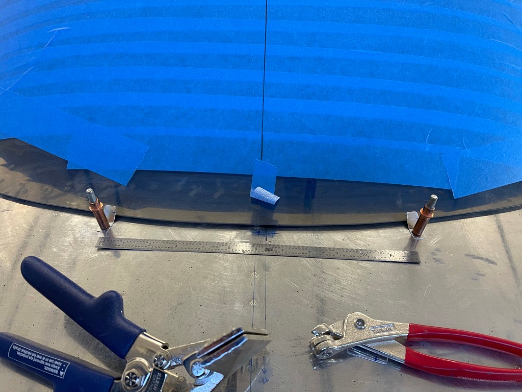
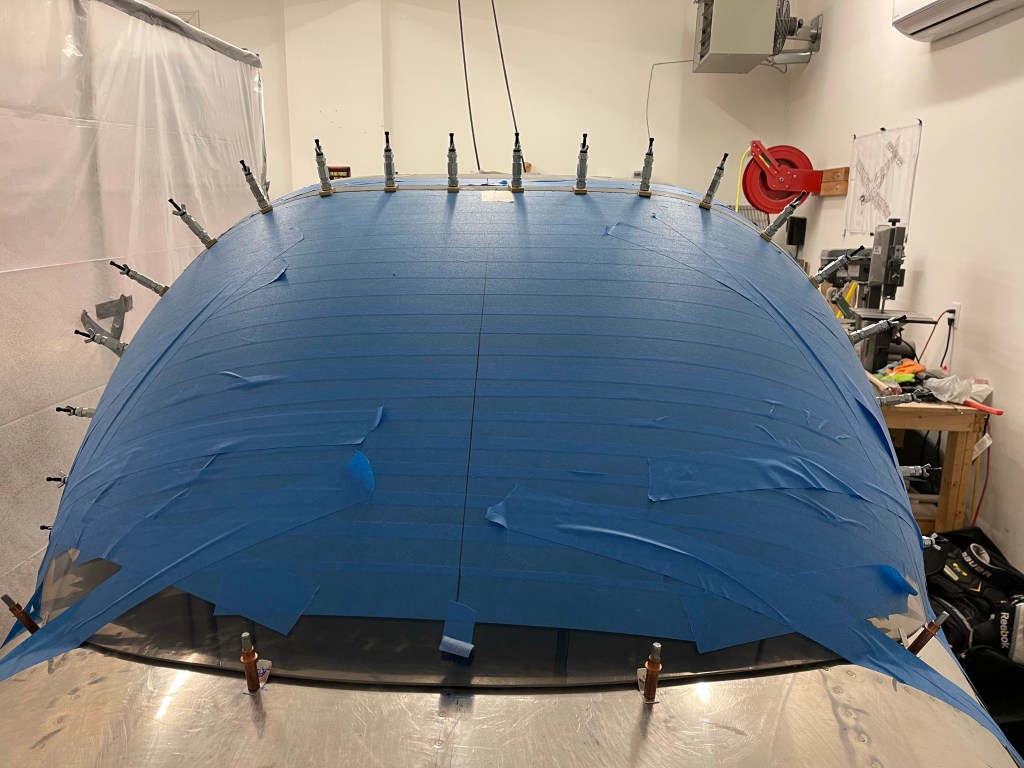
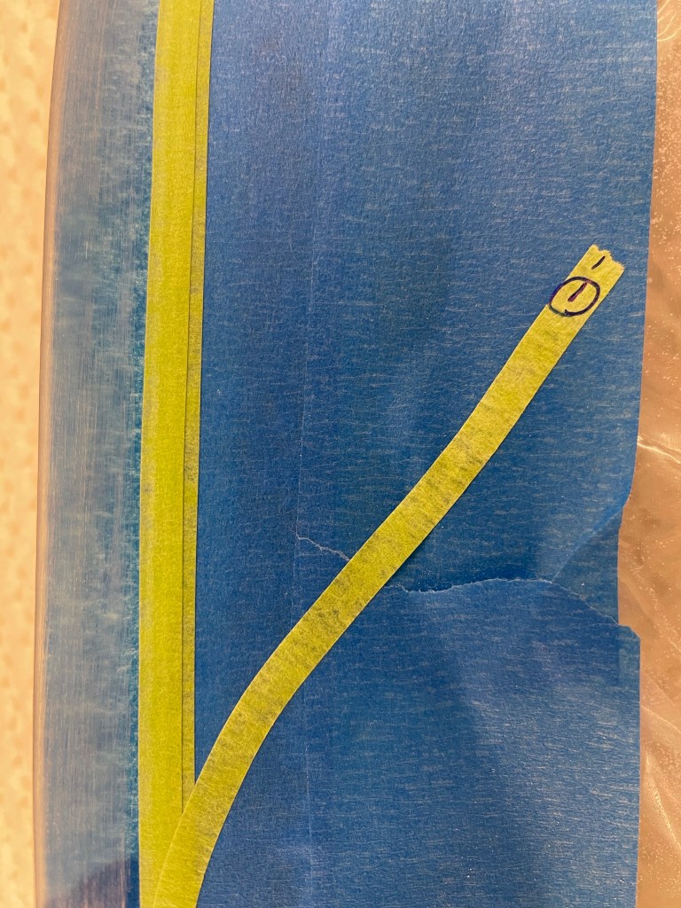
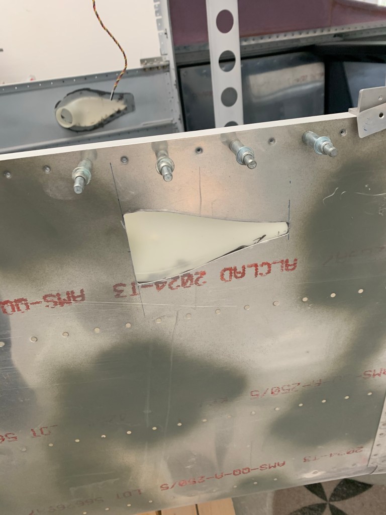
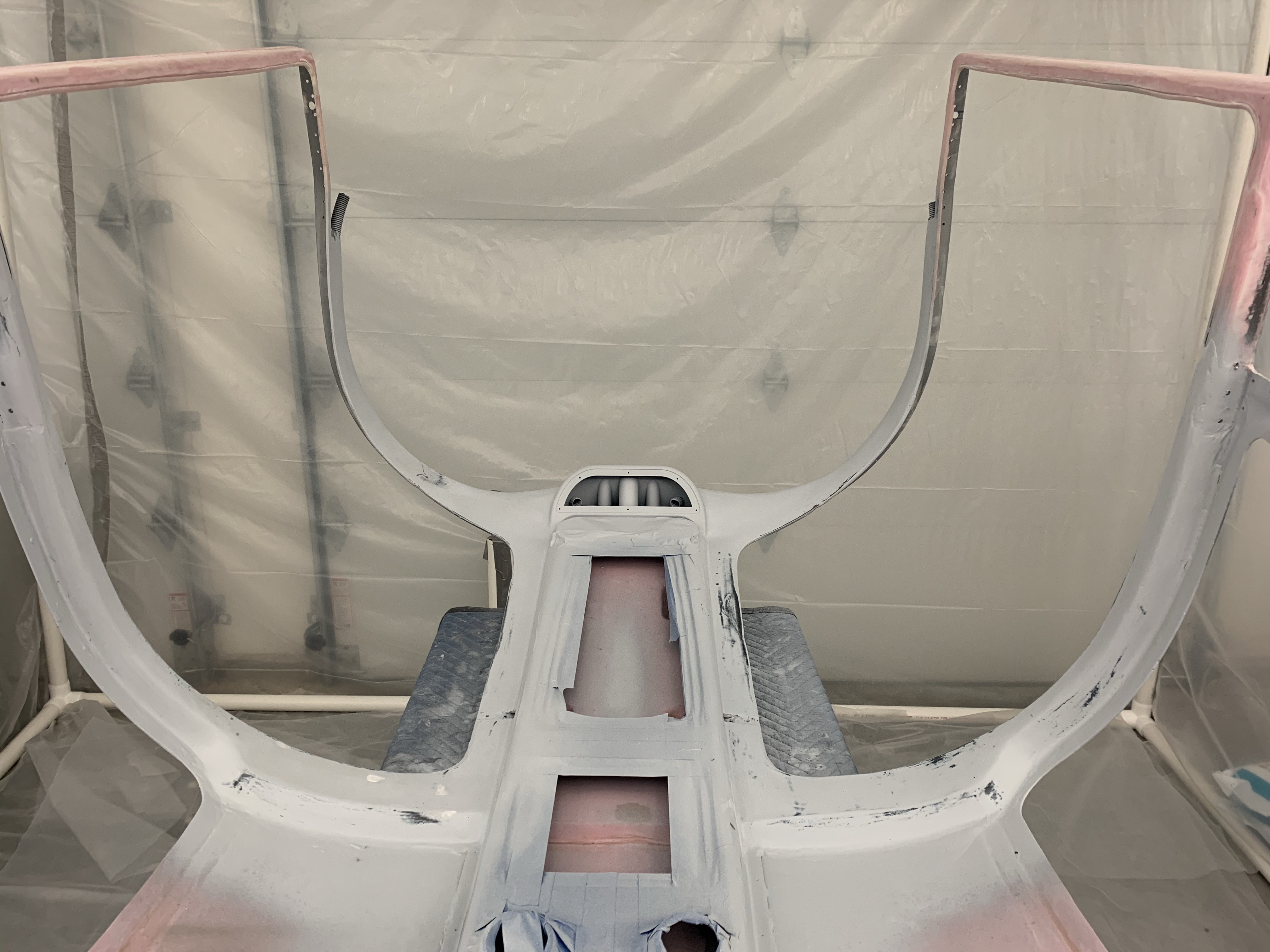
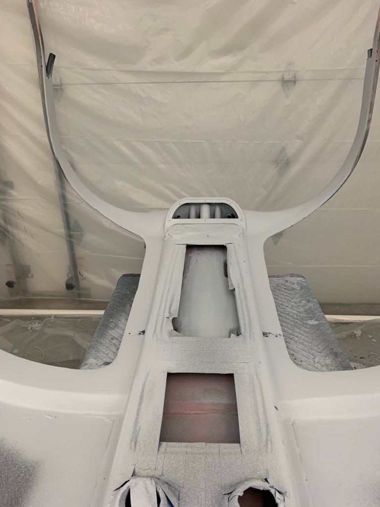
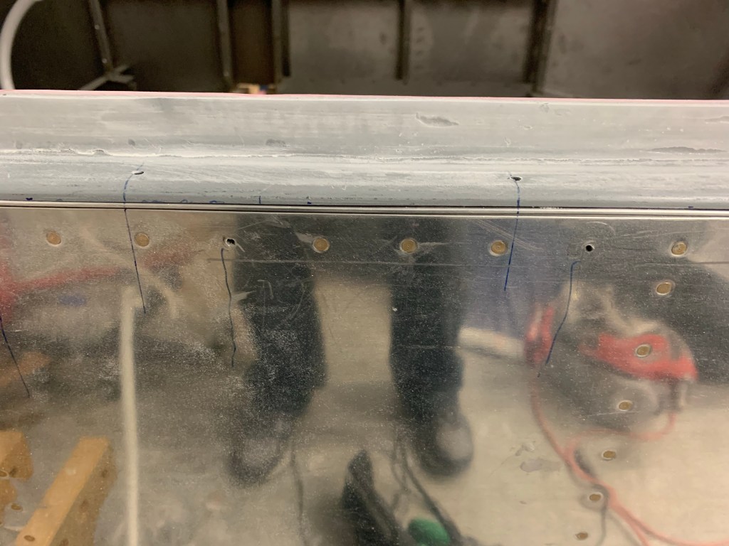
The next part of this process is to do a fiberglass layup along the base of the windscreen and the metal fuselage. To start, you mark the boundaries of the fairing area with high quality electrical tape. For the boundary along the plexiglass, I used my 7″ radius tool to mark where it hit the plexiglass along the center and front areas. I also did that along the sides, but the curve starts changing from an inside radius to flat along the sides. So I sat inside and looked at it visually and adjusted it a little bit downwards until I got something that I thought was visually desirable. In order to make sure the fairing is at an equal height on both sides, I made a template aligned with the skin seam to mark the same location on both sides. Making sure to be as close to 90 degrees as possible to the joggle/Silpruf line I just finished.
Template for fairing height on each sideUpper Line for fairing
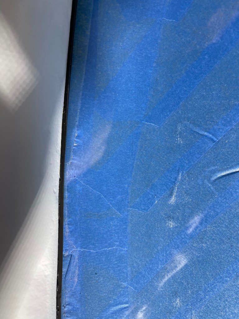
I then marked the line around the bottom part of the fairing on the metal fuselage. I came back approx 2″ from the base of the Plexiglas, but ended up adjusting the sides downward a bit later on.
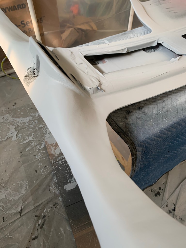
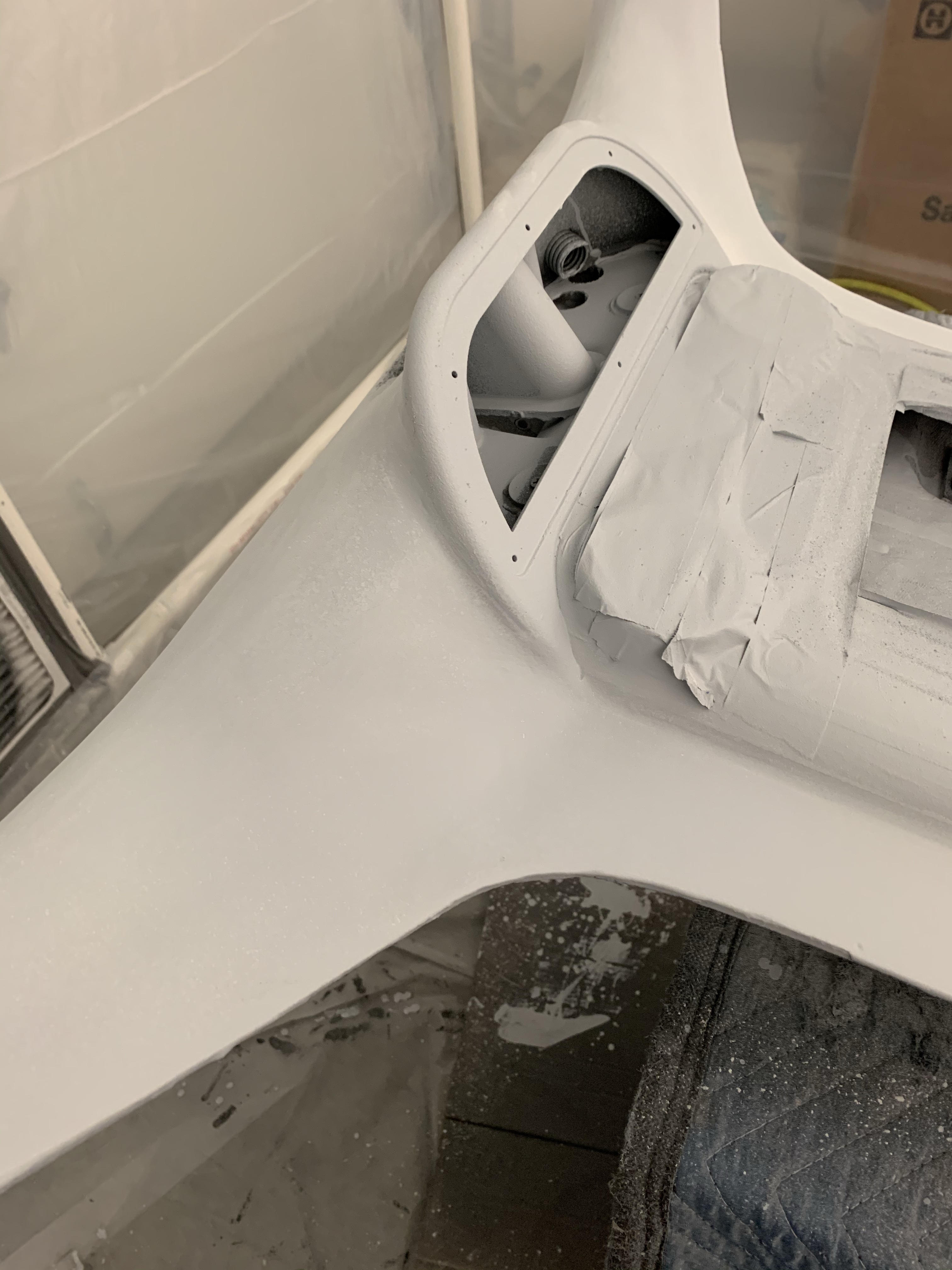
Left side Fairing boundaryRight side fairing boundary
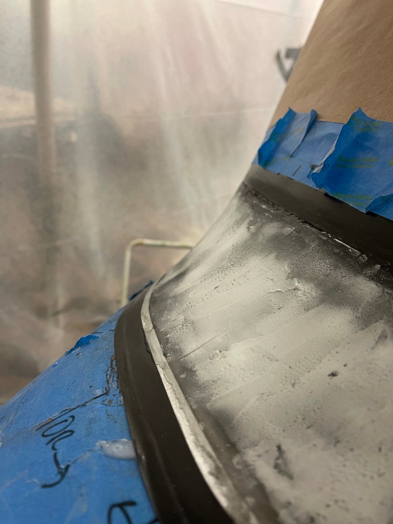
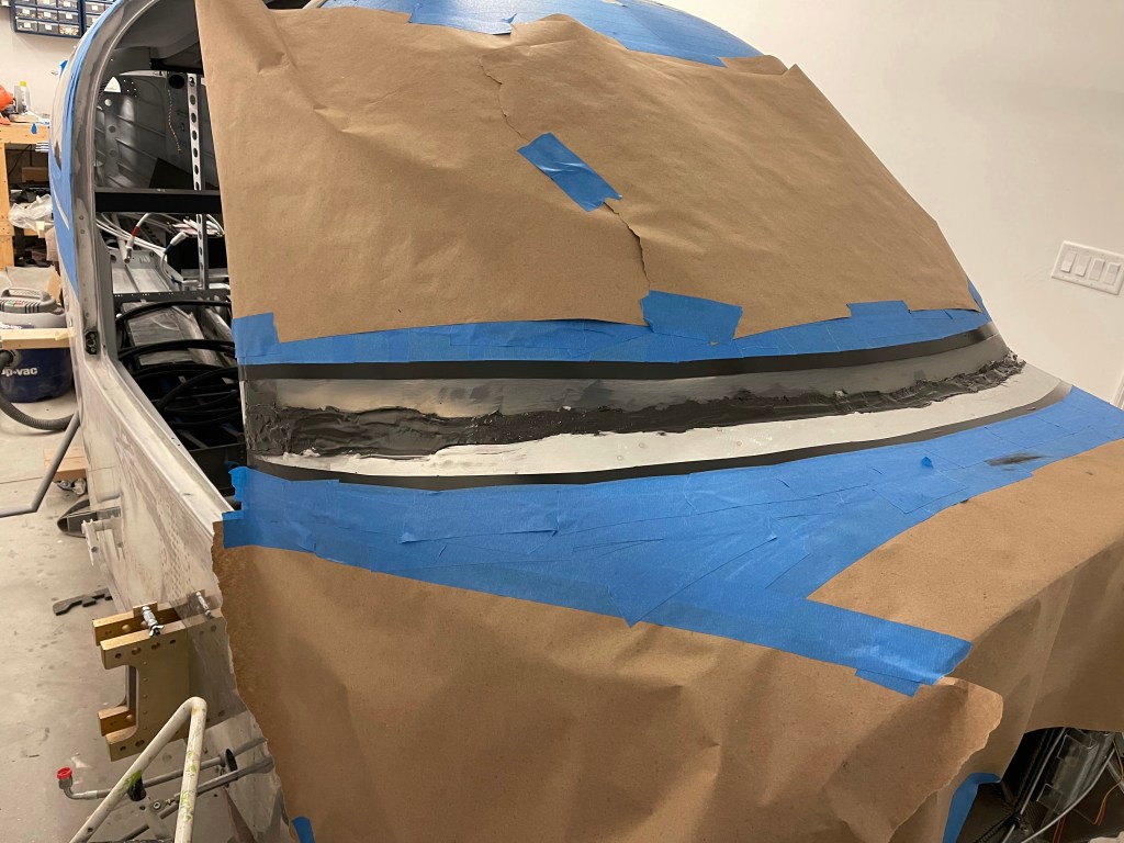
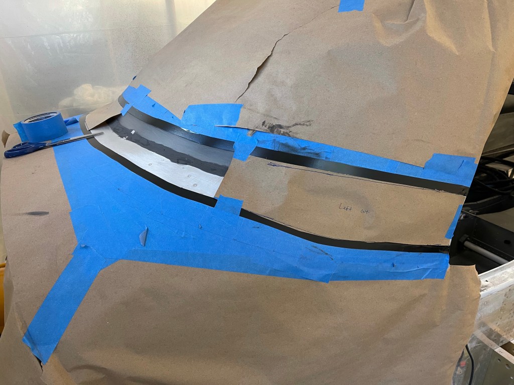
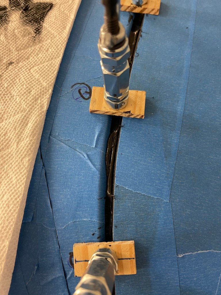
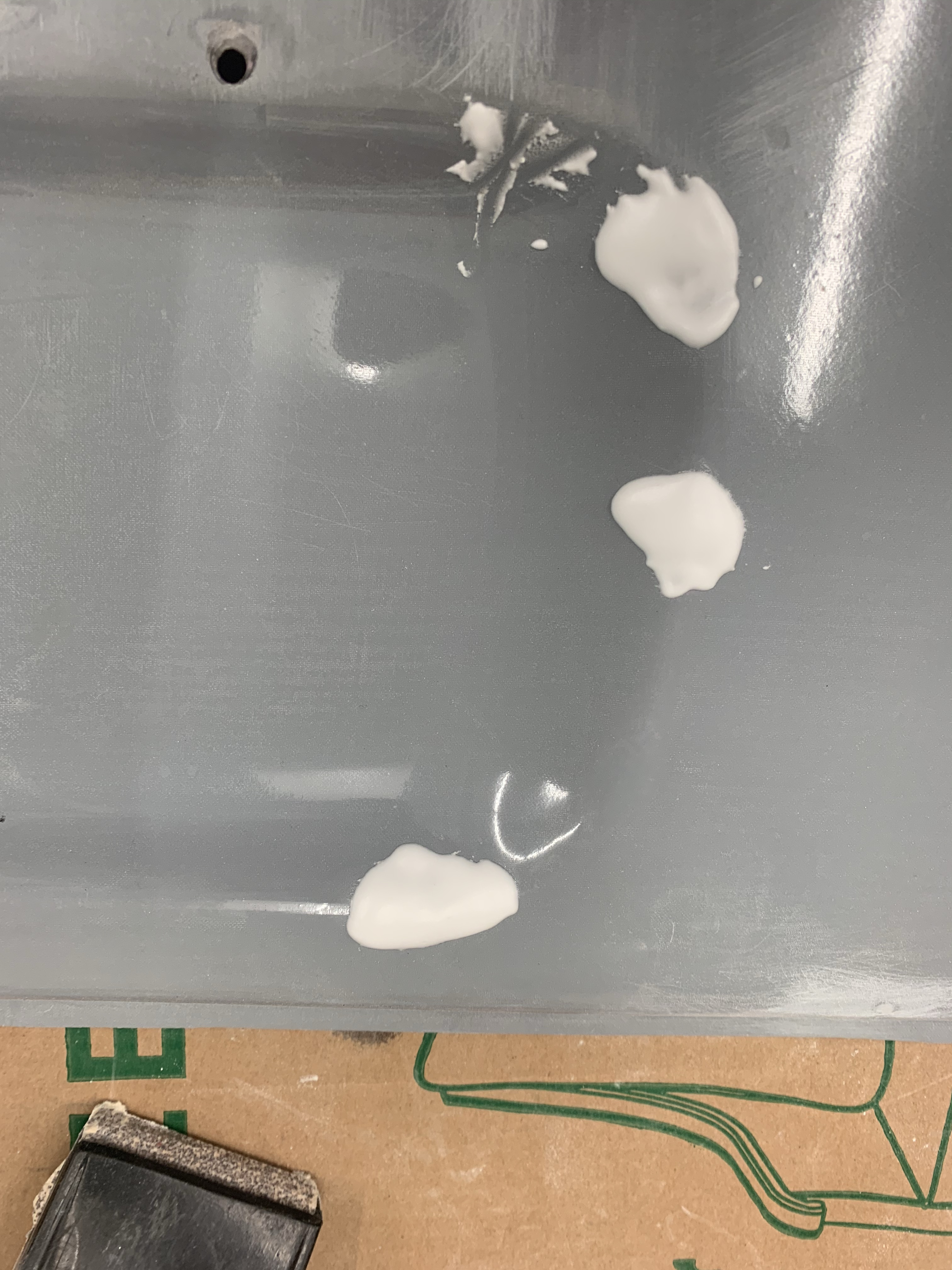
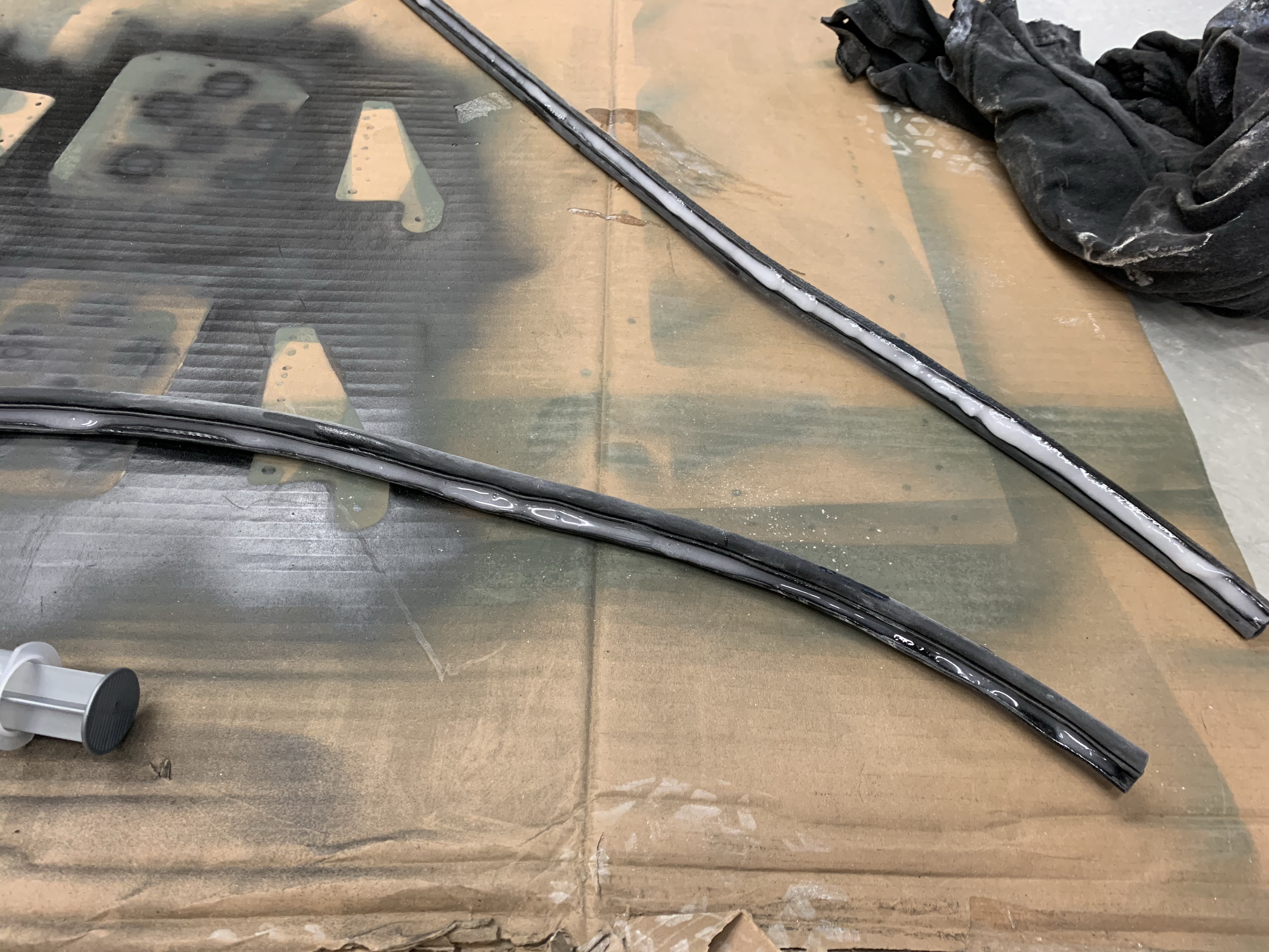
Everything was then sanded very well with 50 grit sandpaper to ensure proper bonding. I then cleaned the surface really well with distilled alcohol until no sanding residue came off. Next up was to mix up epoxy and micro to fill the gap at the base of the windscreen. I tinted this mixture with black tint. Another hint I got was to paint the insides of the clips that hold the windscreen in place black too, which I had done prior to riveting them in place. As the curve flattens out on the sides, more micro was added downwards to blend the the two surfaces.
Tinted micro and epoxy on left sideMicro/Expoxy from right side
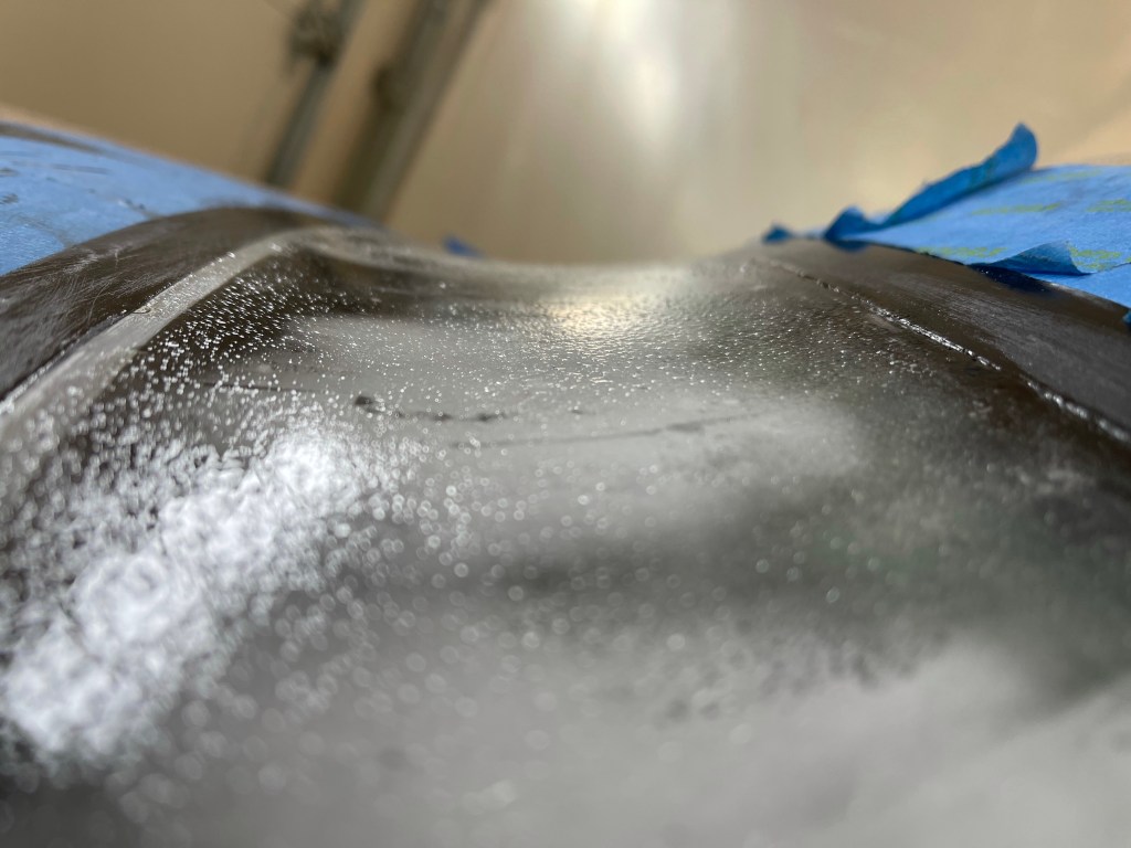
Then I sanded the micro mixture down the next day after it cured. There were a couple of low spots mostly along the sides, so I added a little more and sanded the remainder the next day.
Sanded Micro on leftSanded micro on right
Once the micro was sanded down I re-looked at the gap needing to be filled with fiberglass.
I decided to follow the video series that Van’s put together for the RV-14 here: https://www.vansaircraft.com/faq/canopy-fiberglass-fairing-how-to-video-series/. There are a couple of main differences between the videos and the RV-10 plans. First off the RV-10 plans have you start with small strips of glass and work your way to bigger and bigger strips. The RV-14 videos start with a layer of glass the goes the full width of the tape and it is also tinted so that it produces a completely opaque layer so all you’ll see from the inside is solid black where the layup is. Then the rest is done proceeding with narrow strips to wider strips until you get close to the edge of the first layer. This should create a nice feathered edge. One other slight difference is that the RV-14 videos show a couple of different large side pieces of glass that are cut somewhat on the bias. I cut these too and used them in a similar fashion to the videos.
The RV-14 videos refer to paper templates that come in the plans.. Well since there is no such thing for the 10, I ended up making templates for the first layer in 4 sections.
Two rightmost templatesleftmost template
I then got to cutting the first layer of glass per my templates, two of the larger side pieces per another template I made.. along with smaller side pieces (about 1″ smaller in all dimensions compared to the larger side piece) along with all of the the glass strips called out in the plans.. Adding a couple of 3 ft. 1/4″ strips too. I setup the bench to cut the glass with a craft fabric cutting board underneath along with a rotary cutter, which made fast work of the cuts.
Cutting glass strips
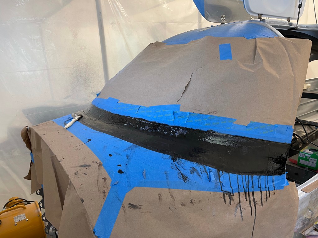
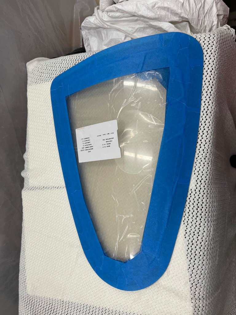
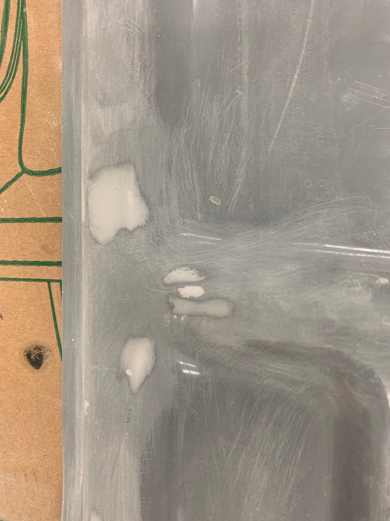
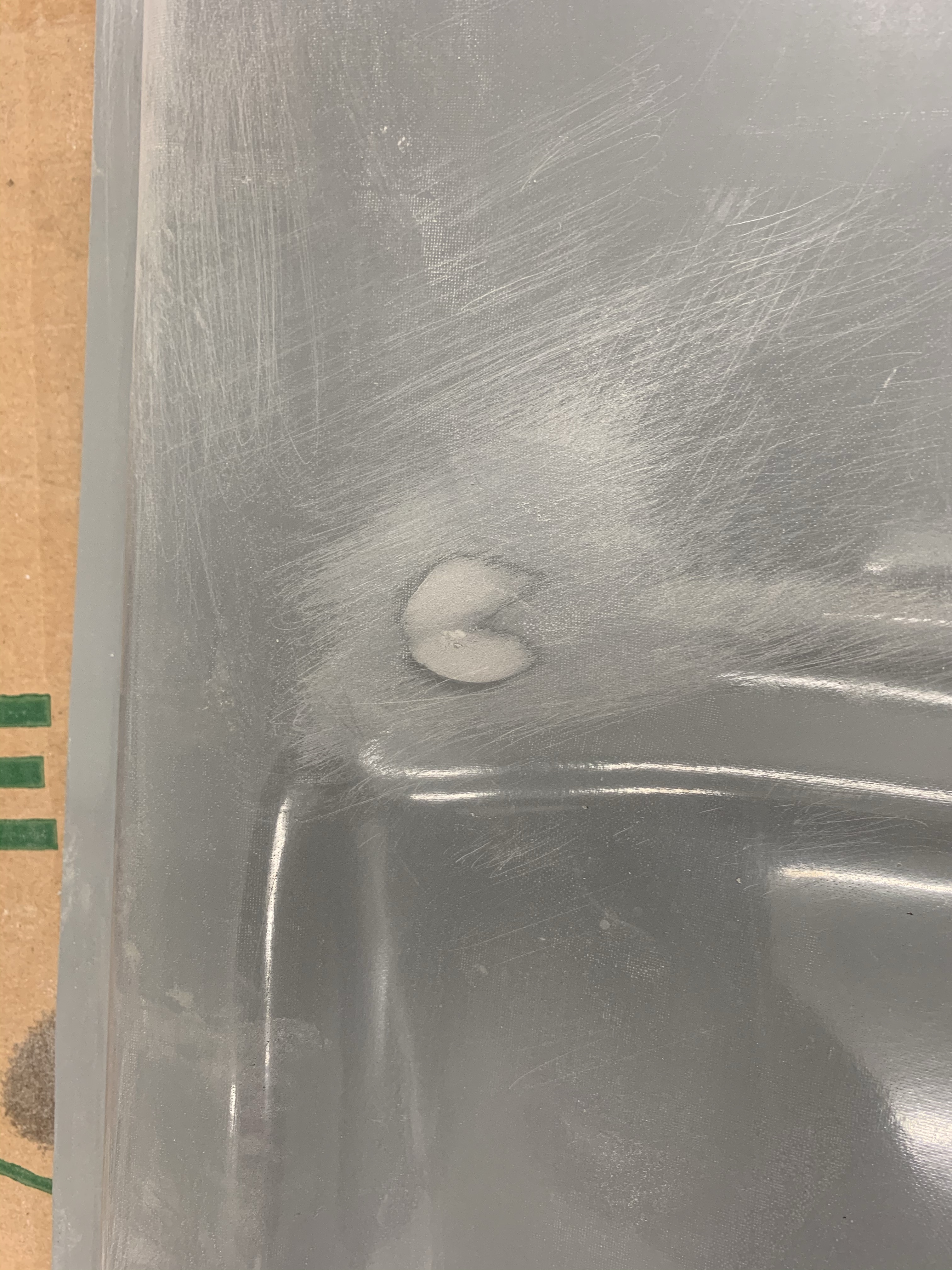
I then mixed up epoxy with the black tint and applied it to the faring area. One thing I noted is that it wasn’t very dark like I saw on the videos. I pressed on all the while thinking something wasn’t right, but figured it might darken up when it cures.. I followed the videos instructions for wetting out the first layers sandwiched in plastic wrap with the tinted resin. I cut them down to size with the templates and placed them into position using a brush to make sure there were minimal air bubbles underneath.
First layer from the outside
After the layer cured.. I just wasn’t happy. I knew I should have stopped when the resin applied to the windscreen was not thick and opaque like in the videos. Below you can see how translucent the first layer really was.. I talked with another builder who followed this process and a similar thing happened to him too. He also has a friend who has something similar and left it this way and is very unhappy with the results.. The bottom line is the videos depict that there isn’t much tint needed when you mix it up with the epoxy, when in fact I felt like I had to pour half my bottle in to get it to the thickness and opaqueness I desired… Thankfully it’s fiberglass and can be fixed… So I spent a few sessions over the next few days sanding away the layer along the window until I got back down to plexi again. Lesson learned… I didn’t bother sanding the layer on the metal too much other than to rough it up for adhering to the next layer.
Bad translucent first layer.. Not happy with it!Sanding away the mistake… Completely back to Plexiglas.
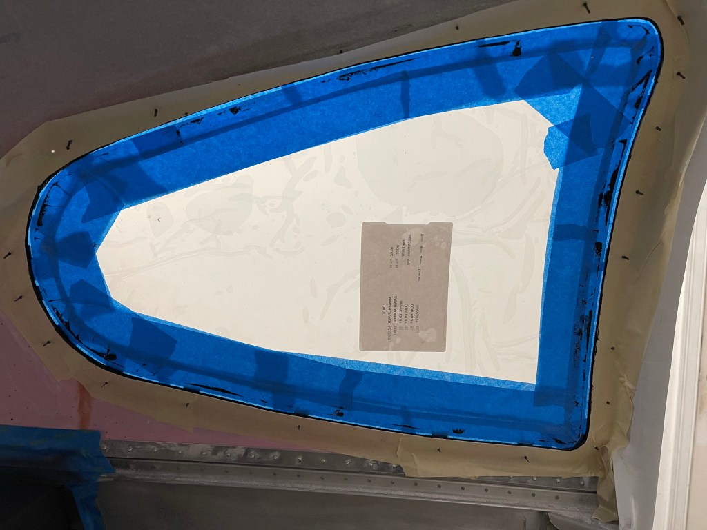
Now with the proper tint to epoxy mixture, I recut some glass from slightly modified templates and applied a new first layer to the windscreen area overlapping somewhat with the existing first layer on the metal.
2nd time view from the outside. A view from the inside.. Much better!!!Closeup of the inside.. Happy with this result. A view of the first layers tinted in black from the outside
Then I didn’t take a whole lot of pictures as you’re working with the pre-cut glass strips, placing them into position and wetting them out with a brush and straight epoxy. Here I was getting close to 8 glass layers in place as I’m wetting out this piece. I also ran back to the cutting table and cut some smaller strips needed as I went along. It was a repetitive process of looking at things with the template and occasionally adding some small strips to build up some areas prior to adding the next wider piece for the next layer. I did do some adjustments along the sides too as there was a slight drop off from the plexiglass layer to the metal.I used small strips of cloth to raise that level up before adding some wider sections to finish off the sides and hopefully I’ll end up with a flat surface in that area.
About 8 layers in
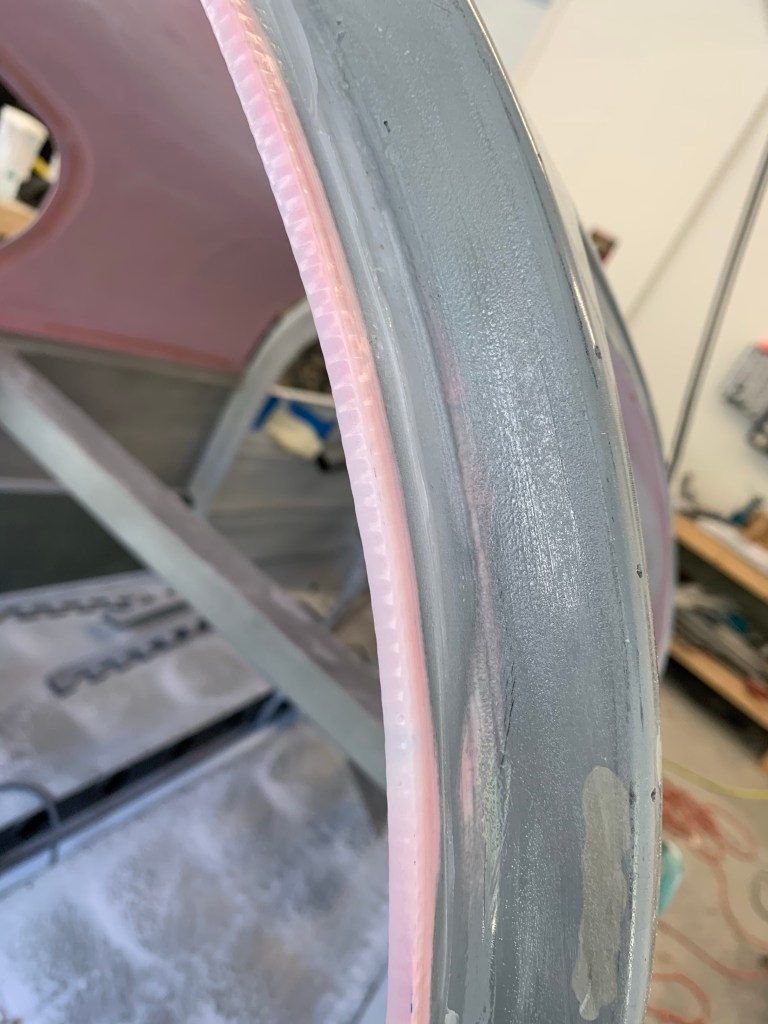
As I approached done.. a Final check of the 7″ radius template shown below pretty close to perfect.
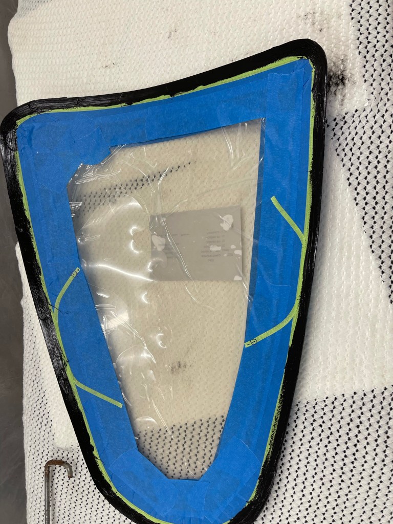
Gap filled in. Final view of the finished layup.
The final step is to brush epoxy on and apply peel ply to finish it off.
Peel Ply!
So now this will cure for a couple days. Then I will be sanding it down with a 7″ radius sanding block across the front and other blocks along the sides. More on that and filling in any low spots on the next post..
I’ve also started working on the wheels/landing gear section while I’m waiting for this to cure… Next major step is to get this puppy on gear! That’ll be a huge milestone!
A couple of pics of all 4 side windows now done with the front right window curing.
Left side windowsRight side windows
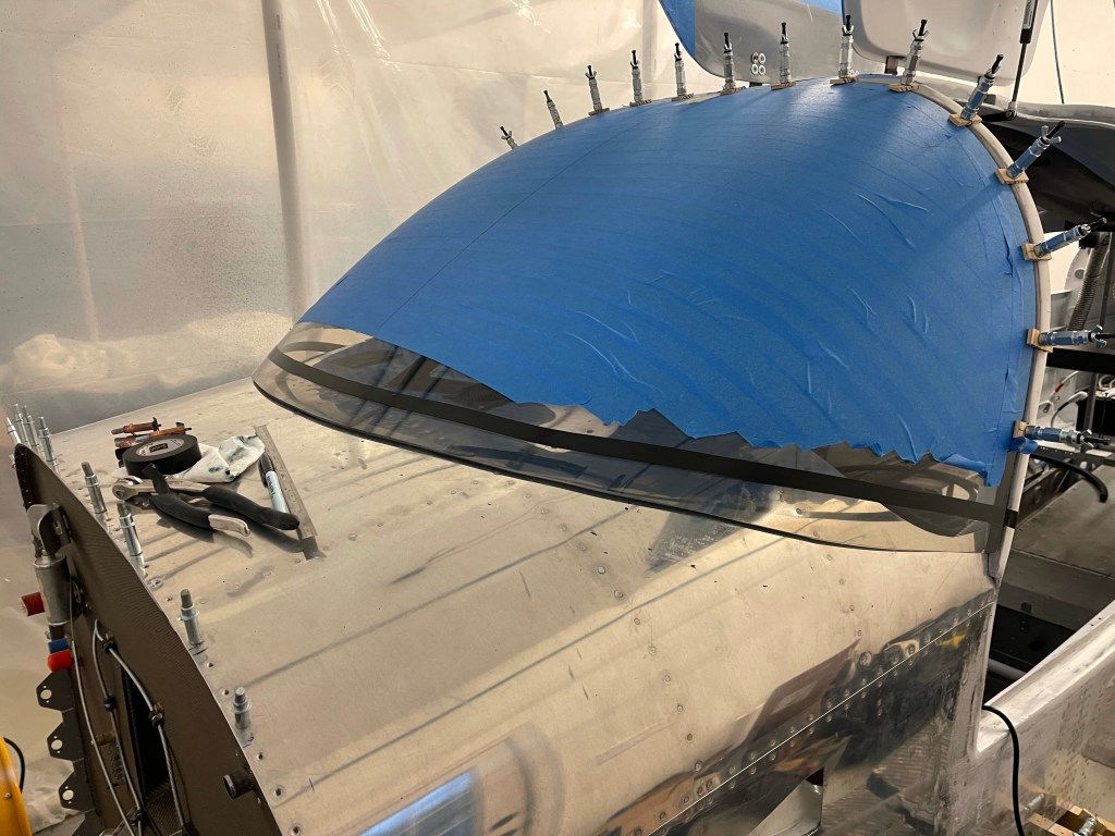
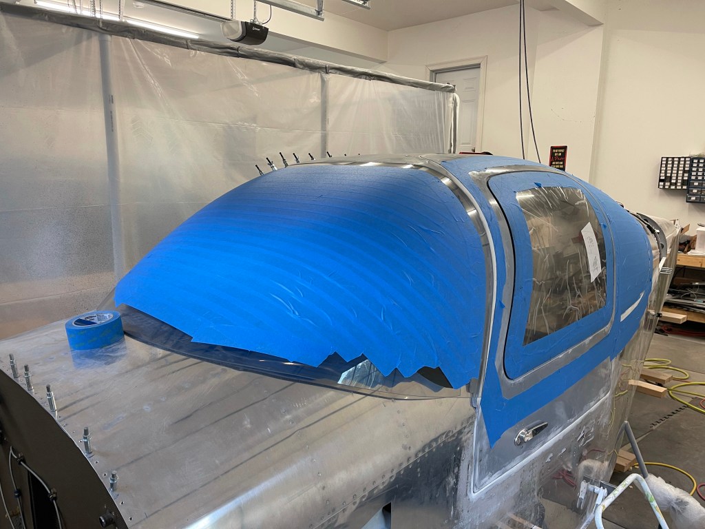
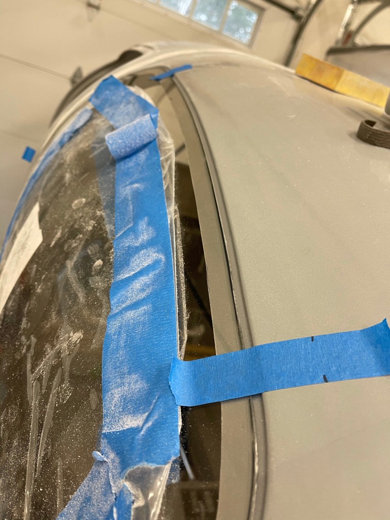
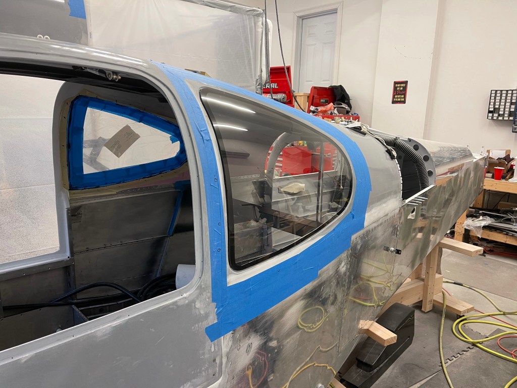
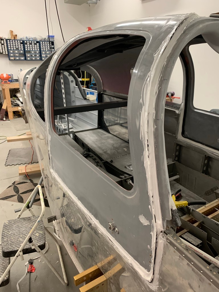
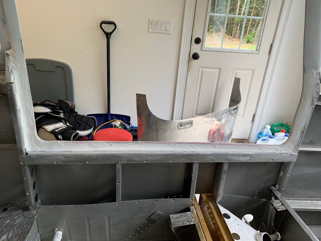
It was then time to start on the windscreen. It was masked off to help protect the plexiglass from getting scratched. Then began the process of trimming. Not too much trimming was needed with the Cee Baileys windows and this one was no exception. I marked the centerline of the fuselage and the window at both the top and bottom to make sure I was always putting it in basically the same position before each marking and trim session. I did trim some off of the front to tilt the window downwards a bit and alleviate the bottom corners bulging outward due to the plexiglass hitting the curved part of the upper forward fuselage. Once I was satisfied with that and made sure that the plexiglass was entirely sitting on the aluminum, I moved on to trim the top. This was solely to create the 3/16” gap which will follow the same Silpruf method as the side windows.
Placing the windscreen in positionMarking the centerline Centerline marked on bottom of windscreen Top gap trimmed
Then I fabricated clips to hold the bottom part of the windscreen in place and put them approx 12” apart along the bottom edge of the windscreen.
Clips being addedFinal test fit with a couple of clecos
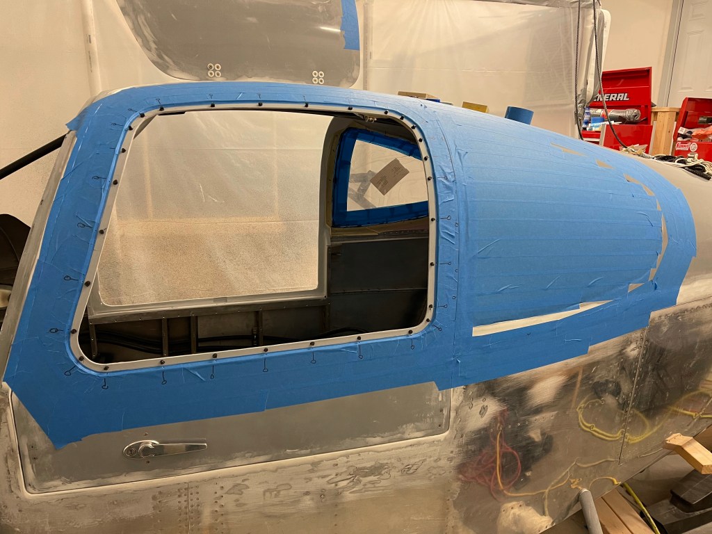
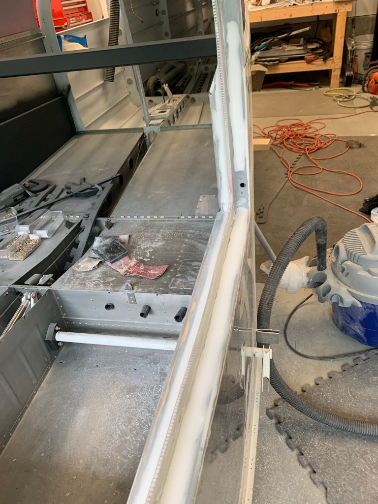
I then installed the Sulpruf standoffs along the joggle and made sure everything was masked around the window.
Standoffs
I then prepped the inside of the top part of the windscreen just like the windows with masking and eventually a boundary layer of Silpruf 12-24 hours ahead of putting the window in. I was a little conservative with the bead of Silpruf I put along the joggle, but wanted to have too much rather than too little. As Zach says in the videos: “ I’d rather you be an overgluer than an undergluer. “
Squeeze outAll done with masking removedFront viewLeft view
The whole masking process of the inside of the window produces a really nice black “line” along the window joggle once the window is in and the tape is pulled.
Silpruf “line”
Next up is to do the bottom interface between the plexiglass and the fuselage. This will be a fiberglass layup mostly following the plans, but I have watched the instructional videos the Van’s has put out on the RV-14, and I’m planning to do it more that way. It’s just a slightly different way to layup the fiberglass with the use of tinted fiberglass the full width of the layup as the first layer. This will provide a very uniform line along the base of the windscreen as you look at it from the inside. To start the process, I made a 7” radius tool to mark the upper bounds of the layup on the plexiglass. More on that fairing on the next post.
I decided quite awhile ago that I wasn’t going to follow the plans for the window install. The main reason is the plans have you bonding the windows in with adhesive and then using fiberglass cloth over the gap between the plexiglass and the fuselage. With all the differing materials expanding and contracting differently, this fiberglass area is prone to cracking, even if done perfectly. I became aware of another process that other builders have been using and is outlined in a 5 part YouTube series here https://www.youtube.com/watch?v=A336SG-fsiI&t=405s . It is used quite extensively in the Glastar/Sportsman series of aircraft and involves using a silicon based Silpruf adhesive. This is the same stuff that is used to hold windows in skyscrapers. Hopefully it’ll be good enough for my lowly RV-10. 🙂
I spent a fair amount of time ordering supplies after watching the videos and taking notes. I began by fabricating a scribe tool from the cap of a wet erase marker. Fortunately my wife had a hot-glue gun, so one less tool to have to buy… 🙂 The idea here is to cut the cap so the pen fits in snug and have the tip of the wooden piece I cut from a popsicle stick be about 3/16″. This tool will be used to follow the indent of the window joggle and the wet erase marker will mark a line 3/16″ away on the window setting the visual gap you will have.
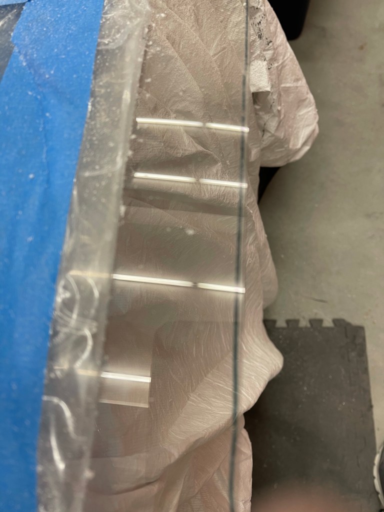
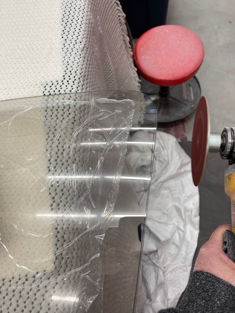
Below you can see the scribe line on one of the rear windows and the angle grinder used to trim the window with sandpaper. It’s helpful to have a white background while doing this to bring out the black line as you’re sanding, so I bought a white blanket and threw a white sheet on the floor.
Below you can see the uniform gap left between the edge of the trimmed window and window joggle.
Looking up the top edge of the windowAnother angleA little more trimming left in the cornerThe final trimmed window.
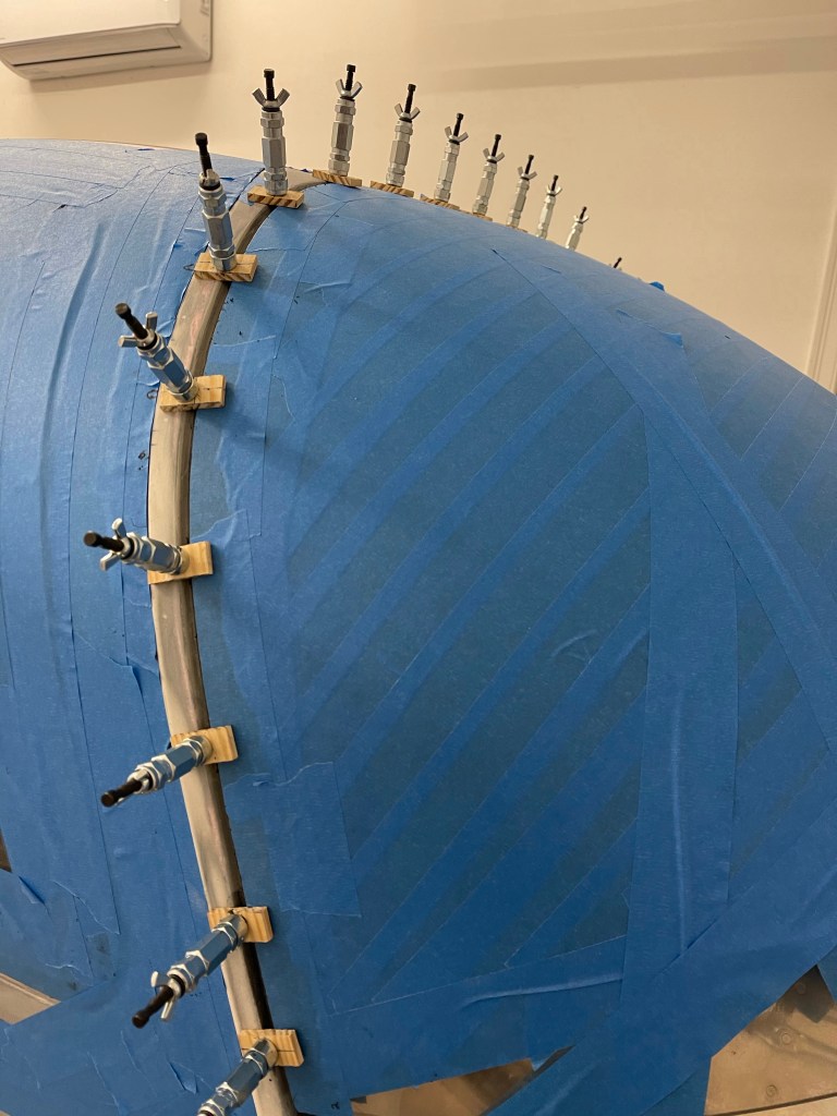
After sanding the edge of the window to get rid of any marks from the sanding process along with putting a radius on the outer edge of the window, #40 holes were drilled along the edges of the window to hold wing-nut clecos with wooden bridges spanning the gap holding the window in place.
Once that is done, a sharpie is used to mark the outer edge of the window in the joggle. This will later be used as a line to mask to with tape. Additionally, the inside of the window was marked with a wet erase marker along the joggle edge. That line will be used to apply a specific masking tape pattern to the inside of the window.
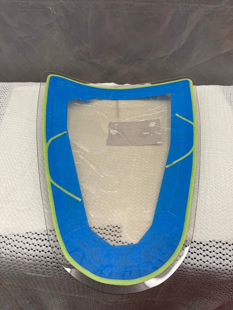
Next up was to mask the inside of the window. This starts with a 1″ blue tape which is kept approx 3/16″ from the line. Then 1/4″ masking tape is used to mask as close to the line as possible without covering the wet-erase line at all. Once satisfied, the line is wiped away with a slightly damp cloth. A second application of 1/4″ tape is applied over the first with an overlap.
Blue masking and double 1/4″ masking doneCloseup showing the 2nd 1/4″ tape overlapping the first to cover its exposed edge.
The front edge of the window was covered in 2″ tape and back-cut with a razor blade. Additional tape was added to cover up any exposed glass.
The right rear window was being worked on at the same time.
After masking to the line in the window joggle and adding a bunch of extra tape (this is due to the Silpruf being silicone and if it gets on the surface of the plane it can cause fisheyes in the paint. So extra precautions were taken.) I got to placing previously Silpruf standoffs around the perimeter of the window. A few days prior, I had run beads of Silpruf out on some scrap metal and let them cure. I used Permatex ultra black gasket maker to adhere these standoffs to the window joggle. Once those cured, I took the window, put it in place, and progressively trimmed the standoffs down in groups of 3-4 at a time until the window was flush (or as flush as possible) with the fuselage.
Left rear standoffsRight rear standoffs.
While this picture is after the window is in, it depicts how I used the razor blade to check to flush to fuselage.
Then when you are ready to install the window, you must lay down a bead of Silpruf on the exposed area of the window and spread it out with your finger. This is referred to as the boundary layer. The first 1/4″ tape is pulled leaving the second 1/4″ tapes edge clean and a small gap between this boundary layer and the tape. This must be done 12-24 hours ahead of actually installing the window so it has some time to partially cure.
Silpruf Boundary layer smeared on windowfirst 1/4″ tape pulled off.Closeup of the gap left between the remaining 1/4″ tape and the boundary layer.
Then after 12-24 hours have elapsed, you spread a small amount of Silpruf to fill in that gap left. Put a generous bead of Silpruf on the window joggle so it’ll cover the entire width of the joggle with some squeeze out. The window is then put into position, cleaning of the squeeze out is done with an approx 1″ wide squeegee and clecos are inserted all around. Additional cleanup is done between the clecos. Then the tape around the perimeter of the window that was placed to the previously marked line was removed. Each cleco was taken out and the wooden bridge was flipped to avoid getting any Silpruf on the fuselage part of the airplane. There is some additional work to spread out the squeeze out on the inside of the window, culminating with the removal of that last 1/4″ tape. Below is a picture after the left rear window was completed. It’ll now sit for several days, of which I kept the garage heat on for the first 2 days.
Left rear window done and curingView of the inside after complete and curing
Seeing I only really have enough clecos for 1 window at a time (and maybe I’m going a bit overboard with the 30-ish clecos I do have) I really want to have a good bond for these things, so it’s worth the extra few days of waiting for one window to cure prior to installing the next one. In the meantime, I’m trimming and getting the front windows ready for install.
View of the gap on the front left door window. Left side windows in place (rear one curing)
Based on my schedule, I left the first window cure for 5 days prior to removing the clecos and moving on to installing the right rear window. Here you can see the finished results, which are a very nice black line around the permitter of the window, which is ascetically pleasing. After paint, the gap will be filled in with Silpruf forming the final look, but that is still quite a ways away.
Closeup of the finished window edge. Slightly different view
Below you can see the right rear window is now installed and curing.
Right rear window installed and curing.
In the meantime, I’ve managed to get the front left door window all prepped and masked off. The Joggle is masked and standoffs are in place and trimmed. All that’s left is to install the window once I’m comfortable removing the clecos from the rear right window once it’s fully cured.
This process will be repeated for the front door windows, then it’ll be onto the windscreen, which is going to be part this process and part laying up a fiberglass base. More on that as I get to it.
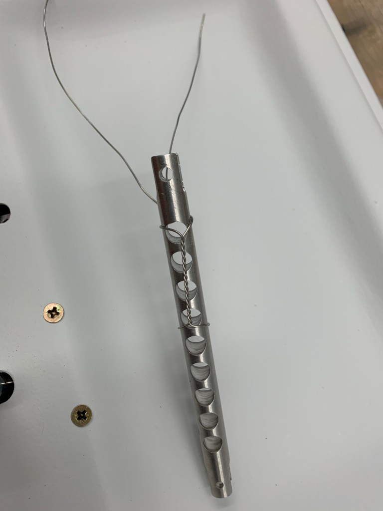
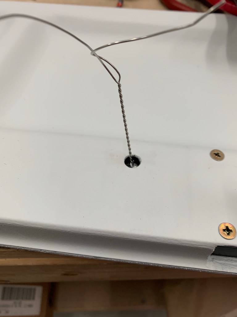
Now that the doors are painted, it was time to put them back together, including the handles and associated racks.. I pulled out the safety wire and finalized the connection between this rod from the Planearound kit to the middle rack assembly. First was to safety wire around the body of the rod leaving plenty of length to the ends to pull through the door and the access hole in the door.
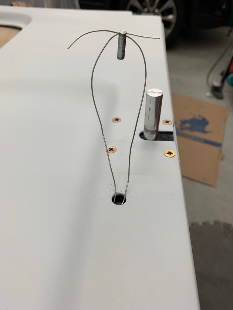
I fished the safety wire up through the hole with the help of needle nose pliers.
Then the wire is passed through the hole on the plane around pin that secures the rod to the rack (inside the door)
Pulling the ends of the wire causes the pin to slide downward and into the hole.
Pin pushed into the holes connecting the rod and rack.
Final step is to twist the wire, snip, and tuck the end into the inside of the door ensuring that it doesn’t snag up on anything while operating the hinges.
I then cut and sanded the Aerosport carbon fiber door sil covers. Reason for doing this now is I need to place the Planearound Cam blocks on the sil, and this will add a small amount of height. I also wanted to drill through this while match drilling the block to the door sil. As you may see below, I had to also cut out a notch from the micro that I had previously applied to get the cam block to sit completely on the sil and provide enough edge distance.
Door Sil CapA view of sil cap from across the plane
With that done, it allowed me to place the cam block on the sil, drill, and setup the cam location.
Cam and Cam Block on the left door.
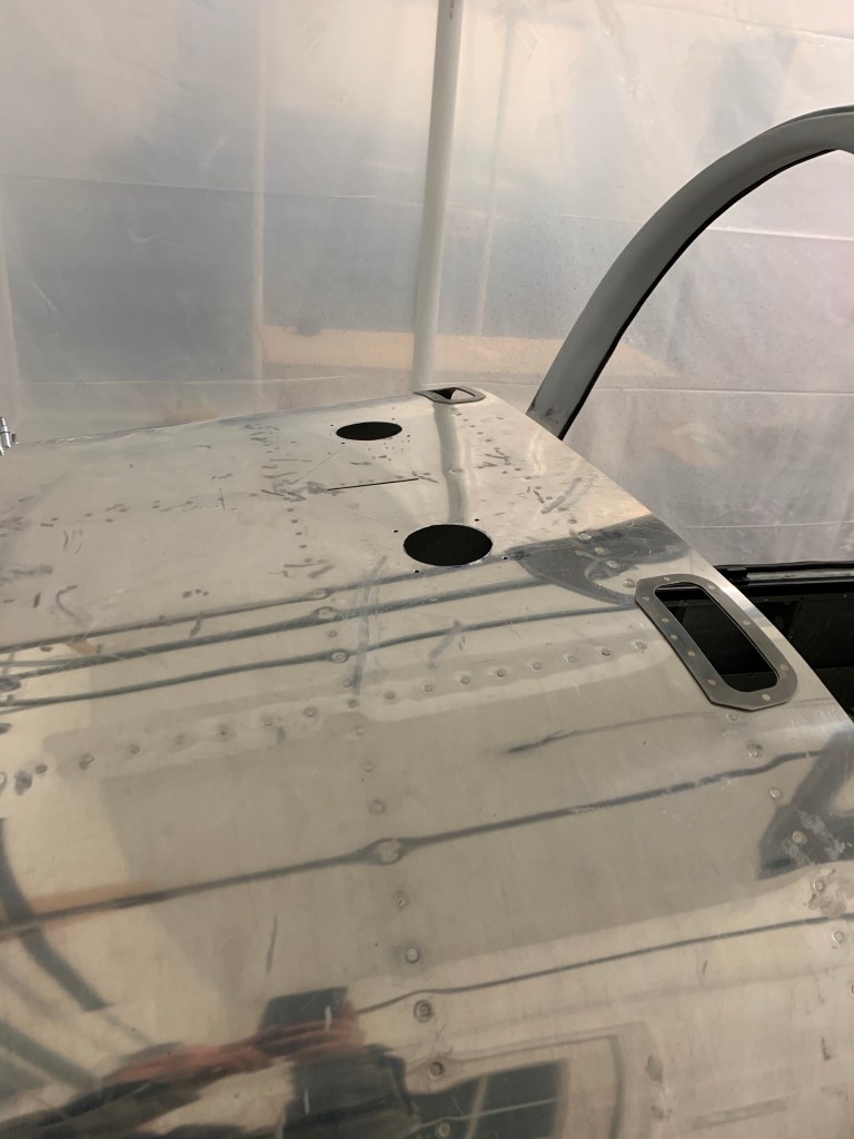
I also spent some time cutting 3″ holes in the upper forward fuselage for defrost fans/avionics cooling.
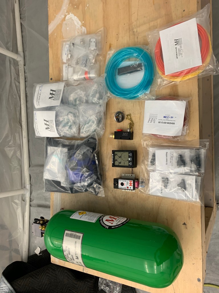
Not that I didn’t know it was coming, but I’m quickly realizing that I’m moving into the expensive part of the build. Some recent goodies that showed up are the Mountain high 4ip oxygen system and my Aerosport 310 Instrument panel!
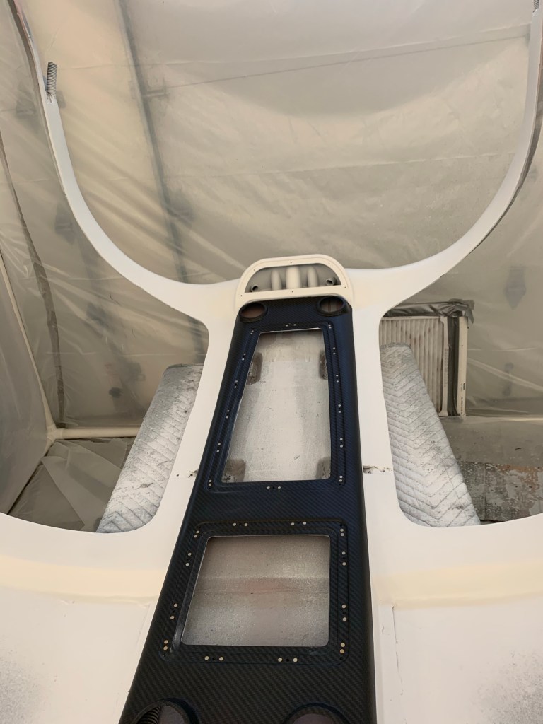
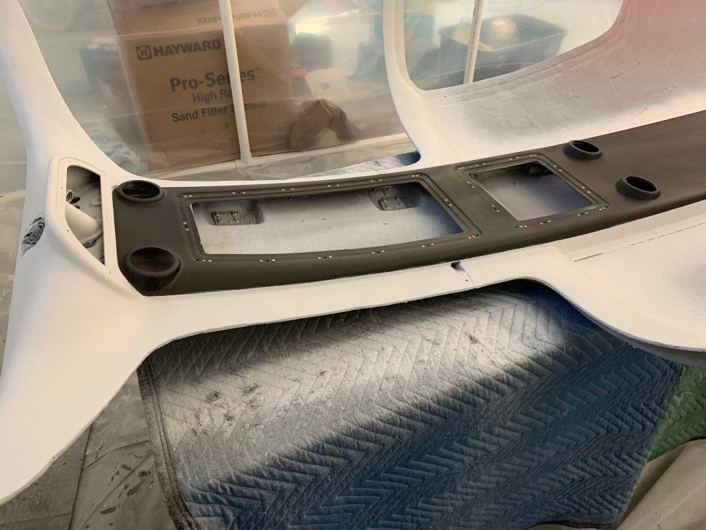
O2!Instrument panel, side panels, and center console test fit.
I also placed a deposit on my engine build planned for April of 2021. Still hoping to go to Aerosport Power in Kamloops, BC Canada in April to build my engine with a tech for 3 days with their build school, but we shall see. Border is still closed with no opening in sight. I also ordered an Airflow systems Air Conditioning system to install as well. It will add some time and expense, but it’ll be worth it hauling the family around in the summer months and taking the edge off.
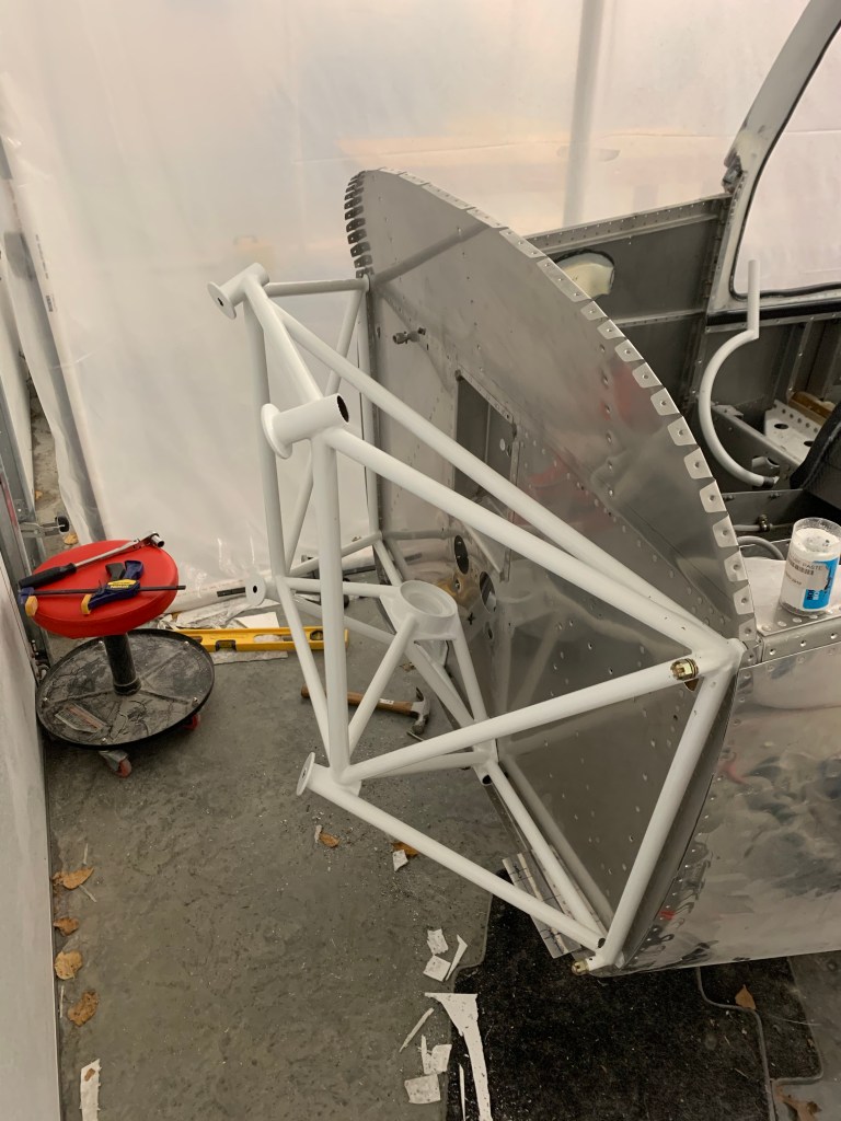
I then got to installing the engine mount by match drilling the holes and placing bolts in place as I went. One word of advise I saw from others was to start at the lower center holes and work upwards. This goes against the plans stating start at the top hole. The mount needed to be pulled outward a bit to match the center of the pre-drilled smaller holes in the firewall. All of the bottom holes aligned well from the start and allowed less stretching of the mount outward to get the hole drilled.
Engine mount temporarilymounted
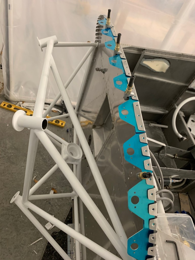
With the engine mount in place, I set out to start working on the sky bolt 1/4 turn fastener install. Really just the flanges for now. The rest will come when I am fitting the cowl after the engine is hung. I chose to install the Skybolts around the entire perimeter of the Firewall. I’ll keep the hinge and pin for the top/bottom cowl split. I played around with placement of the flanges keeping in mind to avoid any interference with the engine mount and the sky bolt receptacle.
Avoiding interference with the engine mount sets the starting position at the top of the firewall
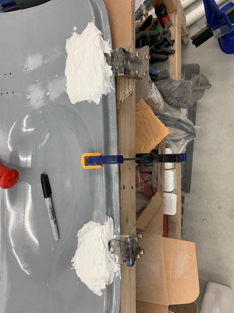
This foam tape was stuck to the edge of the door and a key point was to cover the exposed edges on both sides with packing tape so it releases from the door after the micro dries.
Foam tape on Right DoorSide view of foam tape with packing tape on the sides.
I then slathered up both sides of the tape with micro. I might have gone a little overboard here… Most of this get sanded off in the end.
View of right door complete and curingAn Airplane!
After sanding was completed, it provided a very nice and consistent gap all the way around the door. It also helped fix some spots where the door was ever so slightly above the surface of the cabin top or fuselage. This was mostly in the pillars around the windows/windscreen.
Right Side SandedRepresentative of the gap all the way around.
The process was replicated on the left side along with micro’ing over the fiberglass strip covering the small gap between the cabin top and fuselage.
Left door and side slathered with MicroRight side fuse gap sanded.
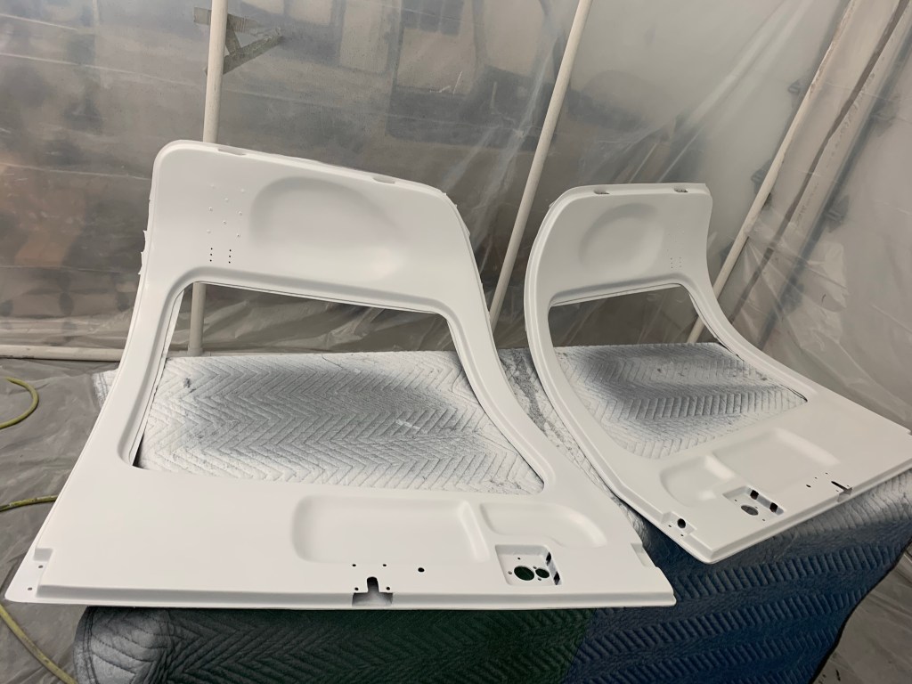
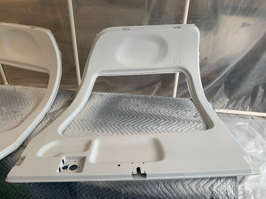
Once all the micro was sanded and I was happy. I moved on to painting the doors. I followed the same process that I did for the overhead. A black PPG DPLF epoxy primer coat followed by PPG K36 high build primer. I did 2 rounds of that after fixing a couple of minor imperfections that really showed through after some paint on it. That was followed by an application of PPG Omni sealer, then 4 coats of the Oxford White base coat. The final step was to use the same Eastwood matte clear coat that I used on the overhead. Hopefully the clear coat will help protect a bit with all the wear and tear these things will endure. Below are some various shots of the doors the latter ones being the completed ones. It’s always hard to take pictures during this process. After the DPLF primer, I’ve basically only got enough time to clean up the gun and get ready for the next coat to be put on while it’s still wet.
Done!
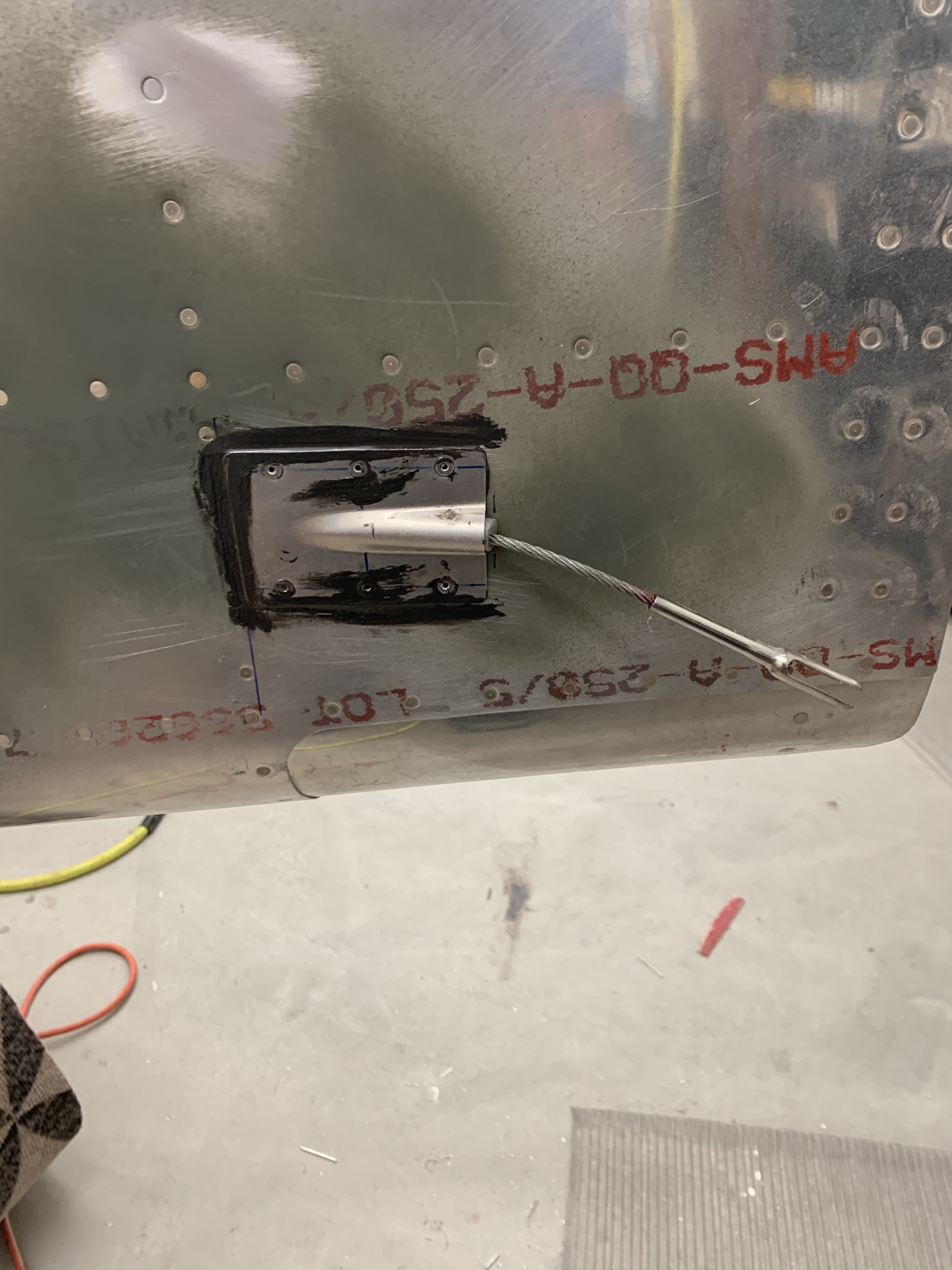
In between paint sessions I spent some time doing some odd and ends like attaching the rudder cable fairings and rear NACA vents with Proseal. I also drilled some holes and riveted on nut plates to accept #6 screws on the bottom cowl plates I added to the firewall some time back. Lots of progress!
Rudder cable fairingsRear NACA vents prosealed in place
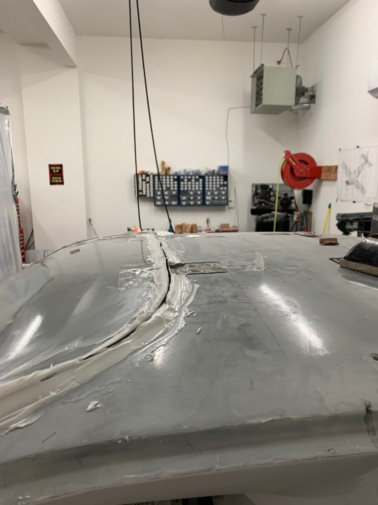
Starting off from where I left off.. I slobbered a fair amount of micro around the bottom of the door openings to blend it with the adjoining structure and the previously done sections of the cabin top.
After sanding smooth. Another application of micro.. rinse and repeat a couple time, mostly just filling in little divots and/or imperfections.
I also used micro to cover over the screws attaching the cabin top to the structure.
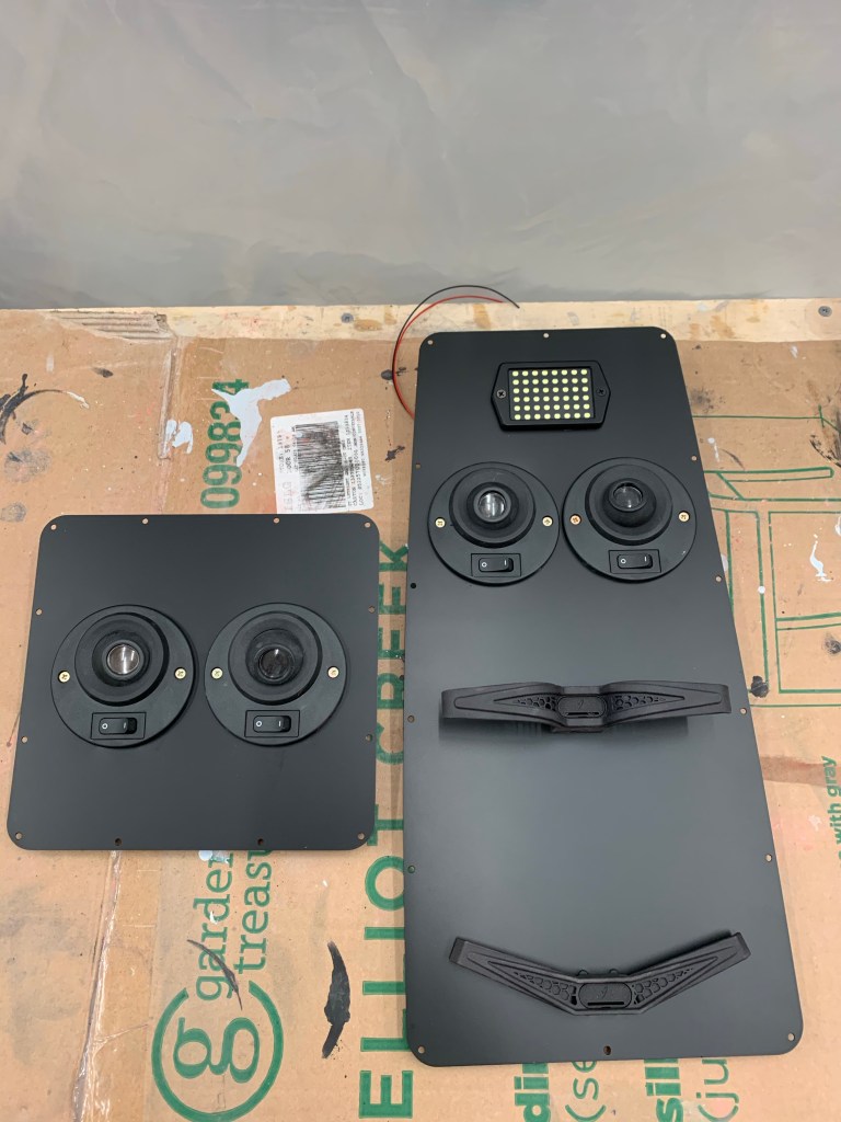
Of course in between sessions of sanding and applying micro.. I got to painting my overhead panels that house the lights. I think it came out really good and hope it blends in well with the dark natural look of the overhead console.
Some other goodies arrived as well. Tires and tube along with my Matco wheels and brakes. I went with Desser Retreads and their 90 degree stem tubes. The items I purchased are listed below:
Here are the wheel, brake, axle, and spacer combos from Matco that I purchased..
WHLNW511.25 – NOSEWHEEL, 5″ 1.25
1
MSCTRA1.5 – WASHER; A6 1.50
2
WHLARV10SL – SPACER SLEEVE, AXLE RV-10
2
WHLA24SPKIT – SPACER, AXLE24 KIT
1
WHLWI600XLT-2 – WHL &BRK WI600 RV-10 CONFIG
2
WHLAXLE24 – AXLE ASSEMBLY, A24 1.25 INCH
1
I’m still a little ways away from putting the plane up on the gear, but it won’t be too terribly long from now.
Then it was back for one last skim coat of micro around the doors and I placed a strip of fiberglass over the gap between the aluminum skin and the cabin top. Lots of bouncing around working mostly off plans for now.
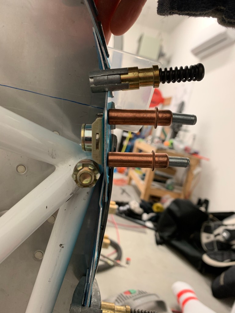
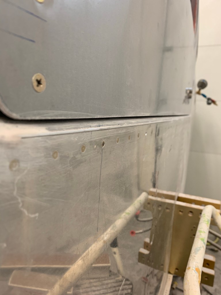
There was also one other thing that I’ve been meaning to do prior to getting too much further along and installing the upper forward fuselage sections and buttoning up the tunnel… I wanted to pressure test my brake and fuel lines to make sure there were no leaks. It would be much easier to fix now while things are still generally accessible. I used my air compressor with an inline regulator and a shut off valve to decouple the air compressor from the lines. I placed a pressure gauge on the other end. The procedure was to get pressure in the lines (I used 20-25psi for the gas lines and 50psi for the brake lines). Make note of pressure reading on the output. Shut off the ball valve and let it sit for about 5 minutes. There should be no loss of pressure. If there is.. you’d spray with soapy water to find any leaks, which I did anyways just to give me peace of mind.
Inlet to the return line on firewallPressure gauge on other endStill holding 22psi after 5-10 minutes
I then tested the fuel supply line. I had to reverse things and measure at the firewall and insert the pressure from the wings. The fuel filters and pump are uni-directional and doing it the other way.. I couldn’t get any pressure to the other end of the line.
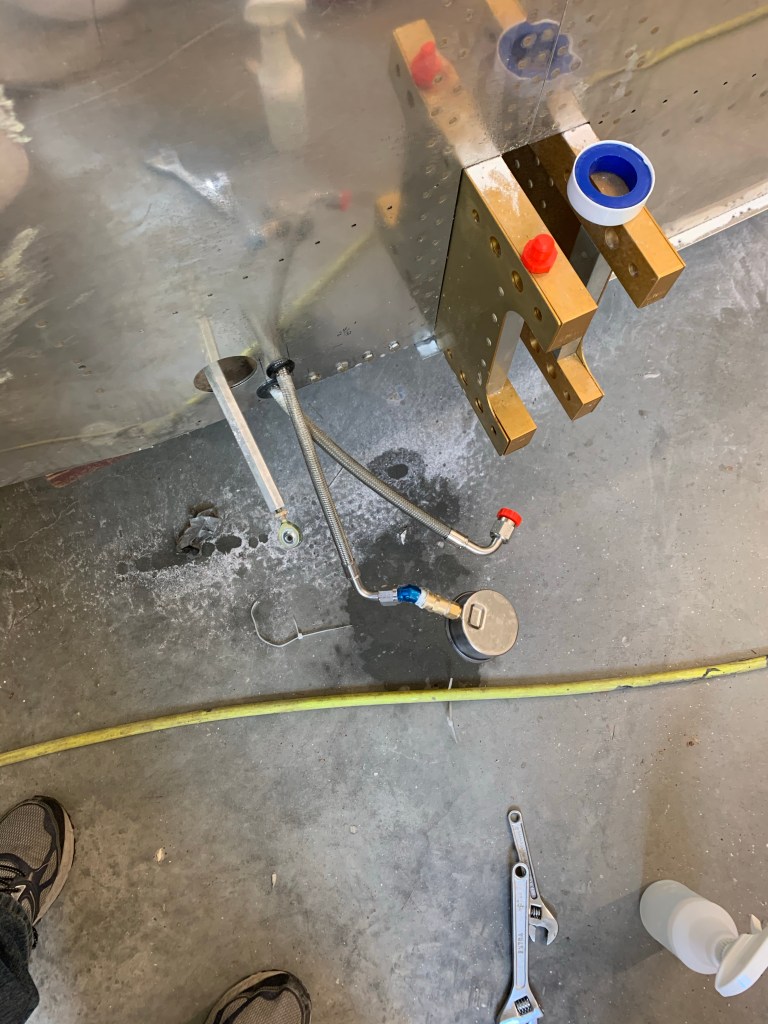
I used a slightly different setup for the brake lines. I got a 1/8″ to 1/4″ NPT adapter to connect into the brake fluid reservoir. I used a 1/4″ NPT tee to connect the gauge into and capped off the AN fittings that go to the gear.
Picture of the brake setup
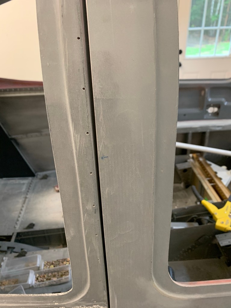
Then it was time to final gap the doors. I’m shooting for an approx 1/8″ gap. This will allow some space for paint, which will narrow that gap down significantly. To prep for that involved a lot of sanding. I re-installed the door handles and McMaster seals for this step so the door would be as close to its final position as possible. Then sand sand and more sanding. I used some thick scrap metal and wrapped 50 grit sandpaper over it to use as a gauge and to also sand back the last little bit by running it back and forth in the gap. Below are some pics during that sanding process.
Here you can see the top part is the typical gap I started with
This was repeated for the left side..
So now it’s time to get the foam tape I ordered and place it between the door and the cabin top and micro on either side of the tape to get a really nice final gap. Micro will also be used to build up a couple of low areas of the cabin top to match the height of the door.
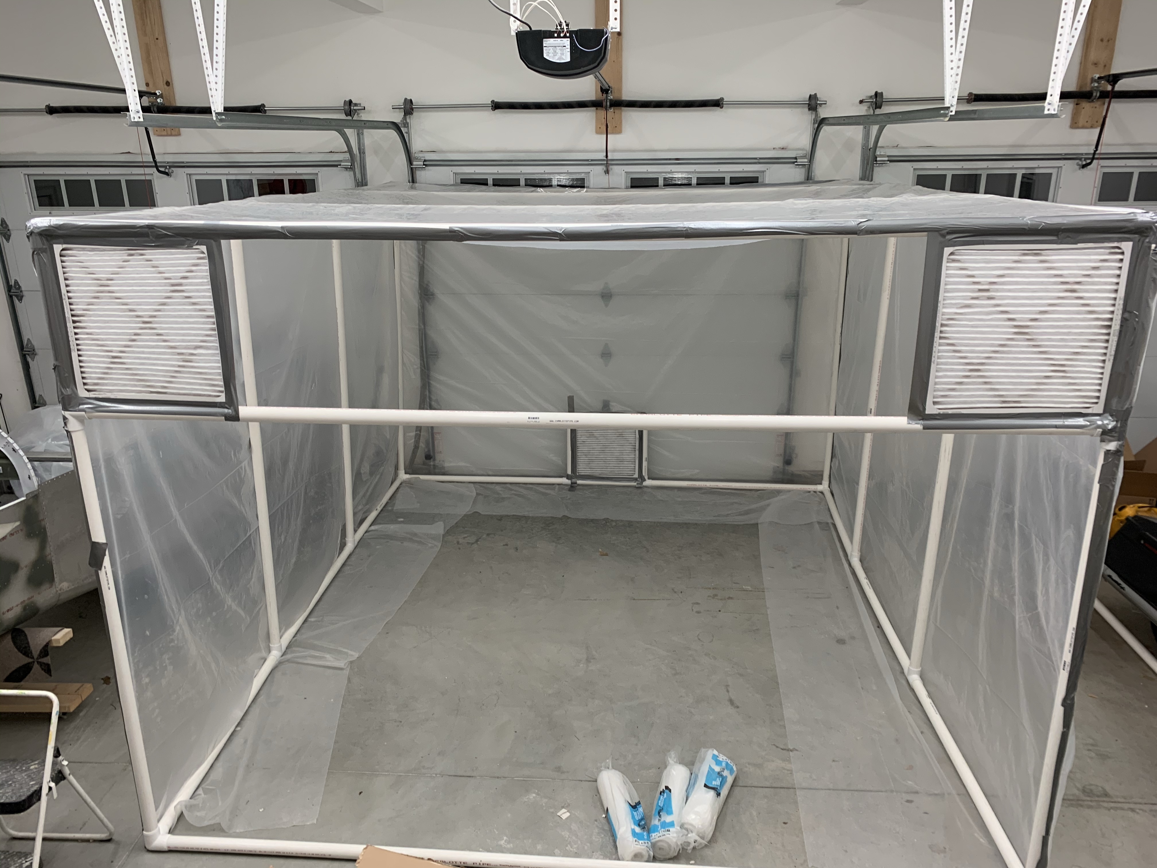
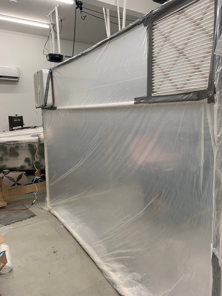
A long overdue update… Finishing the cabin top paint has dragged out longer than anticipated… After some discussion on VAF, I decided to use PPG paints. The suggested method was to use a darker epoxy based primer (like PPG DPLF) and then spray their K36 high build primer over it, wet on wet application. The darker DPLF serves as a guide coat of sorts, but also helps with adhesion. You spray 1 coat of the DPLF let it flash and then spray two coats of the K36. Let it dry, then block sand it stopping if you ever see dark come through. Clean up and do it again. The idea is to sand down the highs, while building up the lows and get something that is optically flat in the end. Knowing that these paints are pretty toxic and smelly.. I first had to setup a spray booth in my garage in order to exhaust all the fumes and overspray out. I looked online and at what a few others had done and built a 10×12 booth out of 1.5″ PVC, plastic sheeting, and a lot of duct tape. This took a while as I had to get all the supplies and do the build itself.
Rough sketch of the boothSupplies are here.
I decided to buy a 12″ “Explosion proof” fan for the exhaust. This basically is a sealed motor type of fan. I’ve seen many people say that they’ve successfully used a standard box fan from Walmart or the like, but I wanted to be as safe as possible and not risk blowing up my house. I am using 20″x20″ furnace filters; 2 for the inlets; and 1 for the exhaust. I am using standard 20″ box fans for the inlet air as those blow shop air into the filter and shouldn’t have hazardous fumes passing through them. A single 20″x20″ furnace filter would catch most of the over spray prior to being sucked out by the exhaust fan.
Booth build in progress. Filters in place
I was going for a negative pressure booth and as I got to testing it, I believe I achieved it as the plastic side walls were being sucked inward with the fans on. In this pic, I only have 1 inlet fan, but did add a 2nd one for more airflow.
Negative pressureExhaust fan at work
The next several pictures are of various stages of the DPLF and high build application. I didn’t take many pics of the black DPLF, because I had to spray the K36 high build about 5-10 minutes after applying the DPLF, so it didn’t leave a lot of time to take pics.
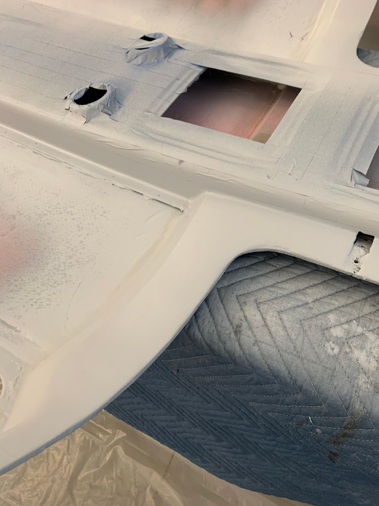
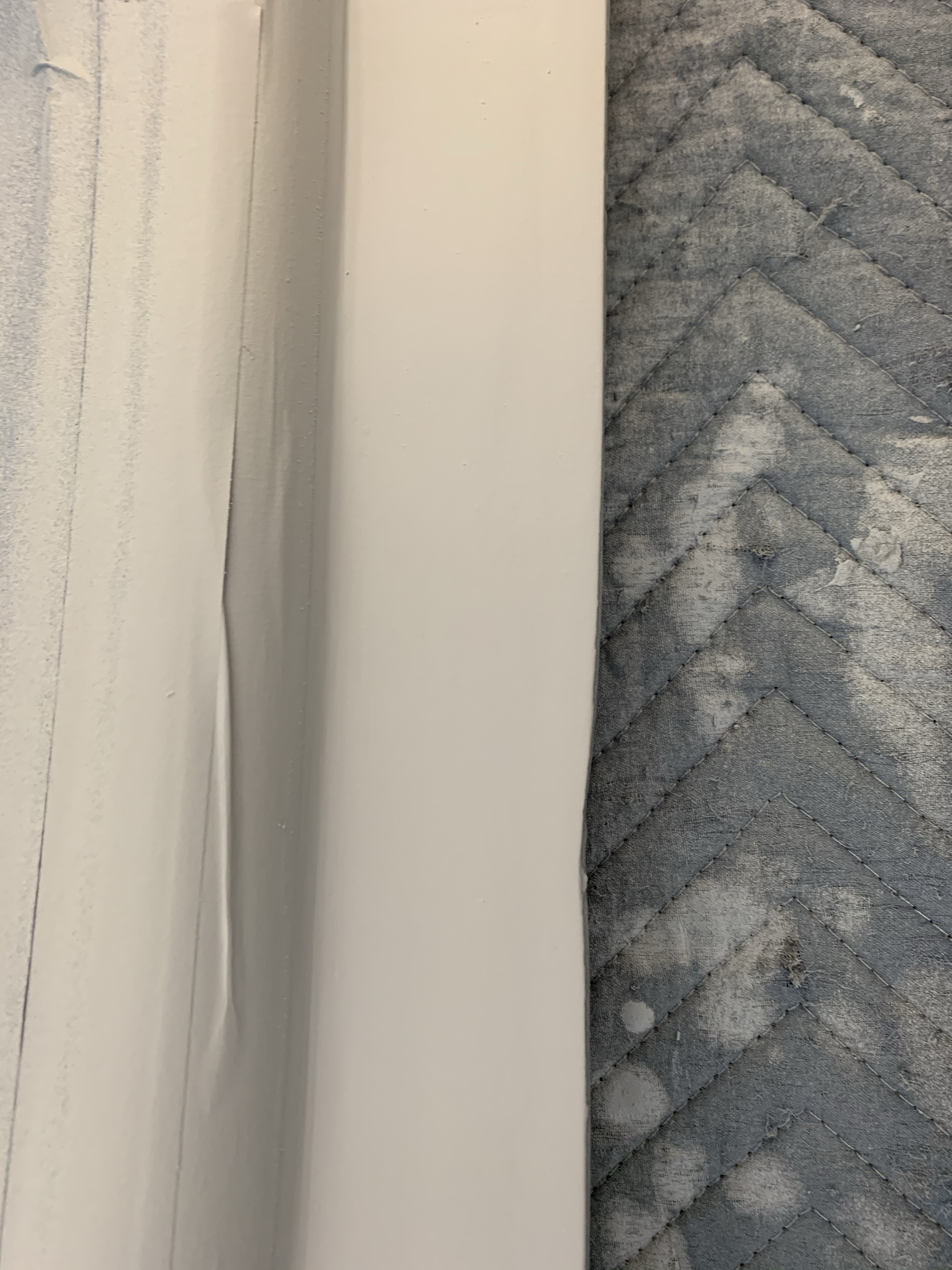
Not perfect, but more high build after this helped the transition.
The interior I’m going after is a two-tone graphite and Oxford white combo. Aerosport told me that their fabrics closely match SEM based paints. So I asked my local PPG dealer to make that color for me wanting to stick with PPG paints at this stage. They were really great to work with. Here is the Oxford White paint for the Cabin Top.
A couple more pics low to the surface.
While waiting for paint to dry etc.. I had some time to work on the doors. There were a few dings and nicks in the doors, which I filled with Micro and sanded smooth as shown below.
Micro over some big dings. Those dings filled in after sanding
I then spent some time on filling in the door hinge pockets. This is needed to have a continuous surface for the McMaster door seal to seat against. I bolted the hinges in place with packing tape around them and used some micro/flox/cabo mixture to fill in the pocket, while leaving enough room for the hinge to slide out.
Micro/Flox/Cabo mix over the door hinge pockets. Space for hinge to slide out. Initial sanding of the door hinge pockets.
Here you can see a coat of the K36 high build with some hints of the darker DPLF coming through after sanding.
Then disaster struck. I had bought a disposable paint cup system ( a clone of the 3M system) to facilitate easier clean up and less use of harsh chemicals for cleanup.. First, while spraying the darker DPLF, I didn’t have the top of the paint cup seated well enough, and caused a slight drip, which I fixed, and then just dealt with it.. But then when I started spraying the K36, Well.. I must have not screwed down the top sufficiently enough because just after I had started to spray the K36 , the paint cup flew off of the spray gun getting paint (probably at least 16 oz.) all over everything… Leaving a big mess to clean up and me calling it a night at that point…
Huge mess of paint on the floor.. Thankful all on plastic. After wiping off the bulk of the mess..
I then had to sand and start again for that coat.. it ended up okay in the end, but very frustrating when it happened… You can see here that I got some paint splatter on my hood. I opted for a fresh air system here as I did have a 3M cartridge-based system, but with these paints containing isocyanates, which don’t have an odor, there’s no good way to know for sure that your mask is working fine. Just because you don’t smell anything doesn’t mean you’re protected.
Some paint splatter on my fresh-air hood.
Then it was on to the top-coat. My PPG dealer suggested applying an Omni sealer on top of the last K36 coat, so I did that followed by a bunch of coats of the Oxford white.
After the top-coats were done, I removed all the masking, did some basic cleanup and got ready to clear coat the darker natural looking carbon fiber of the cabin top and the Oxford white as well. The darker exposed overhead areas was sanded with 220 grit, 320 grit, and 400 Grit sandpaper and cleaned up. Then a matte clear coat by Eastwood was used to clear coat the entire finished top and below are the results, which I am very happy with. Again, not 100% perfect, but very acceptable, IMHO. The rear areas that aren’t 100% painted will be covered with a fabric headliner material. Cutting and affixing the fiberglass for that area is up next along with getting the interior of the doors ready for paint. I will likely hold off actually paining the interior of the doors until I mount the cabin top and final gap the doors.
A view from the rearLeft side. You can see the paint line is reasonably straightSimilar view from the right side.
I’ll be filling in the front area where the support bar comes in once the top is permanantly attached to the plane. For now, I need to leave this area to be able to bolt down the support bar.
I got started by using a laser level to find the optimal position for the center of the door strut brackets. The end result might have been a little different than this line as I found the brackets tended to want to sit cocked aft and not want to be straight up and down to connect to the center of the rivet pattern (and where there’s a metal backing plate bonded in the door). I also inserted a washer under the right side door to get it to sit the way I wanted it.
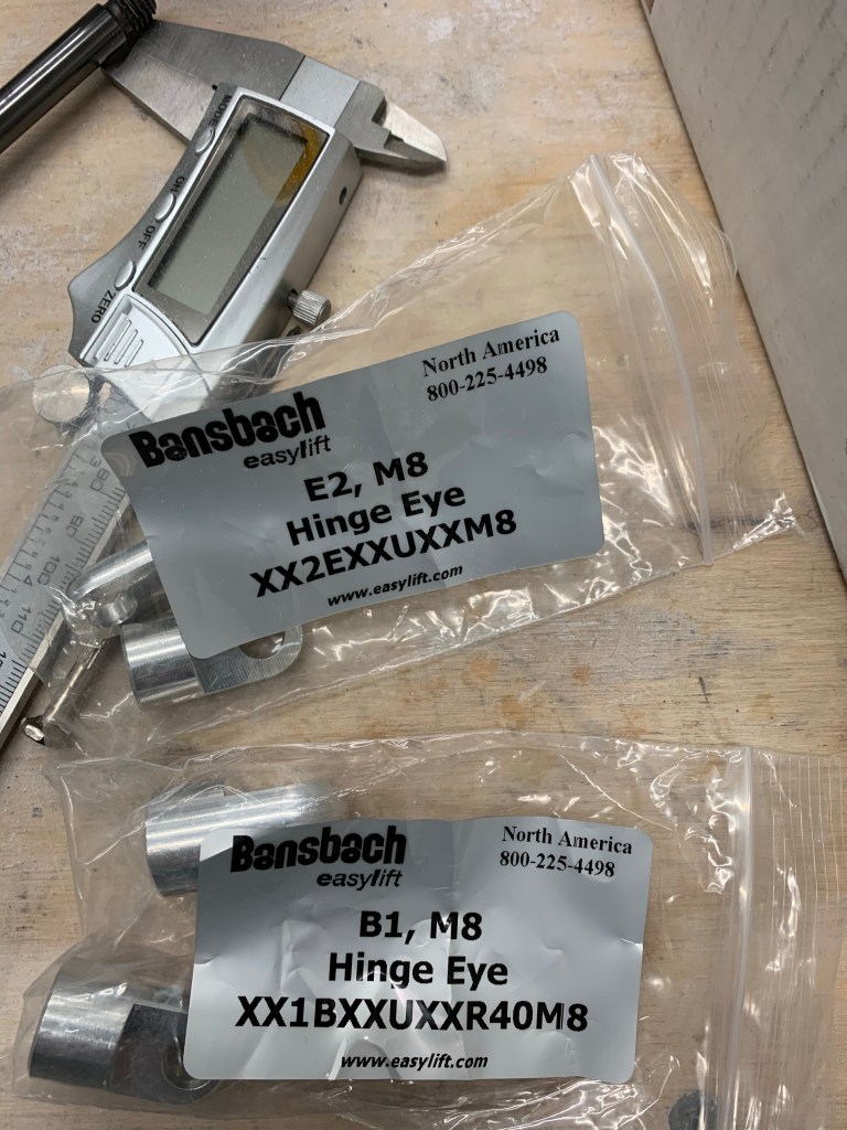
I ordered an aftermarket strut from Bansbach Easylift. The part number was B0N0F50-100-247/XXXN with a 550 newton force. The extra oomph is needed with the extra weight of the Planearound 3rd latch kit so far out on the door as it swings up. I read a bunch of posts on which ends to get and ended up going with 2 E2, M8’s for the door attachment and 2 B1, M8’s for the strut bracket side. The trouble with the B1, M8’s is they are too thick to go into the 3/8″ opening of the strut bracket. I knew this going into it, but read that you can sand them down to fit. Which is what I did, but I still would need to sand more to get the proper washers on either side of the eye. I decided to buy a couple more E2, M8’s to make things 1000% easier. These are 25mm each and the overall length of both plus the gas strut itself is very close to the stock Van’s setup.
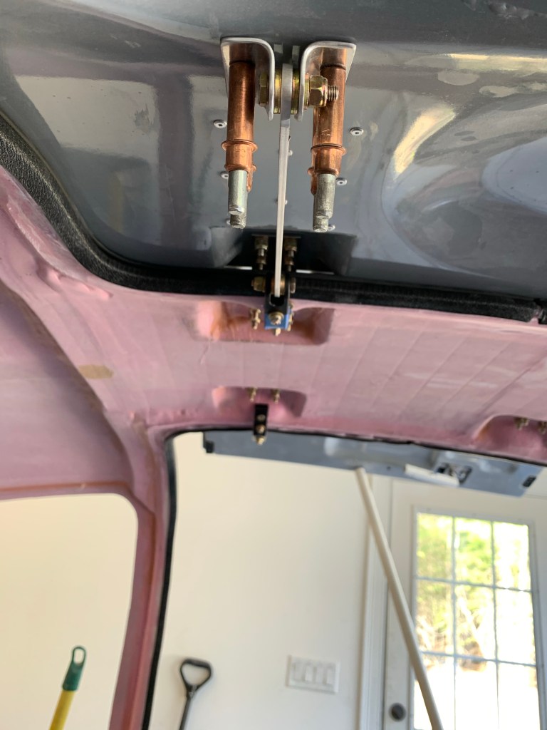
You then fabricate a locating bar out of 1/8″ thick material to locate the brackets on the door. I got this bar attached to the strut bracket and matched drilled the holes into the doors.
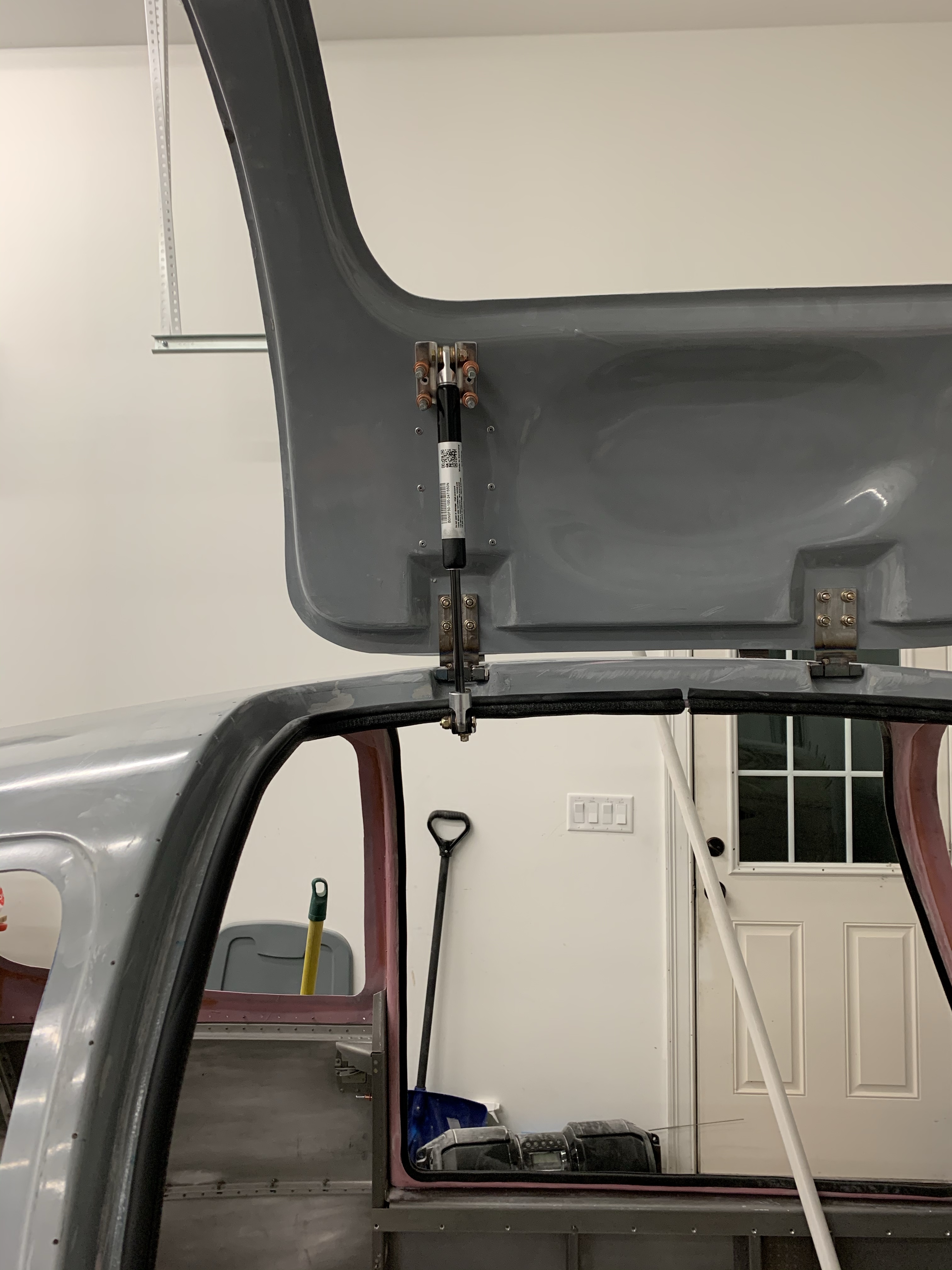
Then I clecoed the bracket to the door for now and what do you know. The door stands on its own!! Below are shots of a couple of different angles.
Both door struts done!Door closed view.
And a short video to show the operation of the doors.
Now it’s onto fitting the overhead console and taking the top off and finishing the insides of both the doors and cabin top on the bench.
Like many others, the bottom lip of the door was greater than 1/4″ from the inner door skin. In order to get a decent seal along that edge, I had to build up the edge. I mixed up some Epoxy with Flox and Cabo and applied it to the lip. I also had one section of the top of the left door that I sanded a little too much and needed to build it back up too. I then took some 1/4″ cardboard all wrapped with packing tape to fill the gap between the door and the lip and create the perfect gap. Any squeeze out was wiped away. I then left it overnight to cure.
Flox/Cabo mix on lower door lipAnother spot to build up. Cardboard spacer
The end result was pretty good.
I then took a bunch of time to sand the inside portion of the lips to make sure it was as close to the 3/16″ grip width for the seal. Because the lip was pretty thin in several spots, I did decide to fill each seal with a flox/cabo mix made relatively thick and push it onto the edge of the door to create a perfect shape for the seal to adhere to. I bought 50′ of seal material, so I used one set for this step, and the other half for the final seal to be used for each door. I had just enough to do this.
The end result!
I was pretty happy with how the edge turned out. I then spent some time sanding the raised area around the perimeter of the seal that resulted and replaced the seal on both doors with new sections. Now it’s onto the door struts. Won’t need to keep holding the door up with a piece of PVC for much longer.