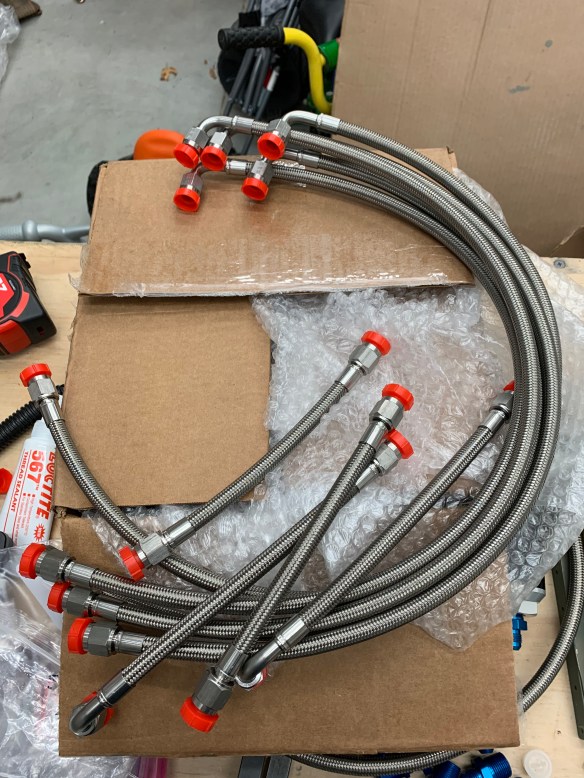
Back to the fuel lines and getting those wrapped up. The hose package from Tom really makes this section easy. It’s mostly just hooking up the hoses between fittings and torquing them properly.
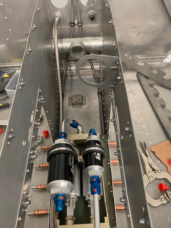
Below are the short supply (bottom chambers of the fuel valve) and return lines between the Andair valve and the tunnel bulkhead fittings. These must go downward and aft as the slots in the tunnel there are for the control sticks between the front seats.

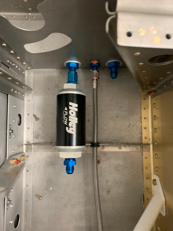
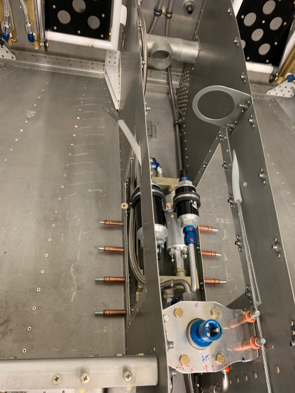
Here you can see the return line passing by the fuel pump/filter module and connecting to the Andair valve right by the “F” marked on metal support bracket.

A similar shot as above where you can see the return line attaching to the firewall fitting.
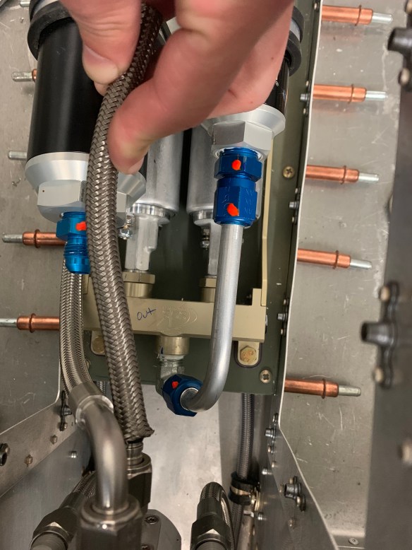
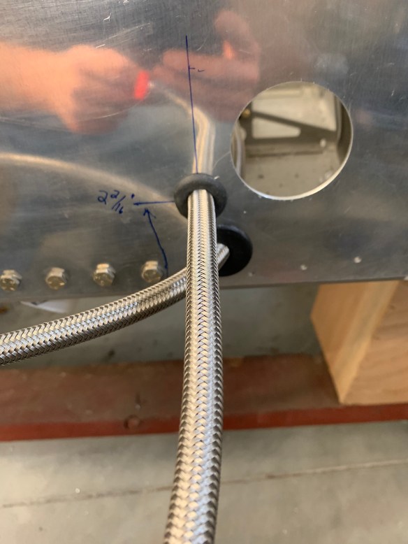
With that done, there are 2 custom hose lengths that need to be figured out. As the filter/pump module might not be placed exactly the same between any 2 people. The 2 custom hoses are from the Andair valve to the input of the pre-filter and from the output of the post-filter to the firewall fitting. The latter being the easy one. The one from the valve to the pre-filter is very tight. The hose is pretty rigid for such a short run and doesn’t have a good bend radius as a result. Below you can see me trying to figure out the hose length needed using some extra hose Tom sent to measure with.
Fitting and hose attached to Andair valve and marking where the fitting to the pre-filter is located
Cut the hose to length and put second mock fitting on that end.
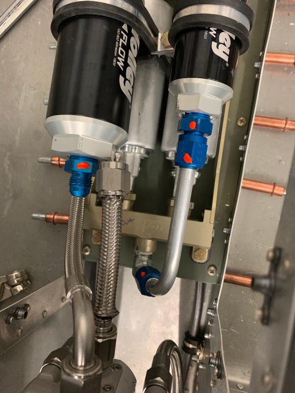
As you can see it’s a very close fit and I’ll need to discuss with Tom what the best thing to do here is. I almost suspect a hard line might need to be made for this short run. Hes on vacation and I didn’t want to bother him, so I’ll get that figured out over the next week or so. I might be able to move the pump/filter module forward a little bit in order to get some more room between the two. The below pic shows the mock up of the supply line (the right-most line) from the post-filter to the firewall fitting. Much more room to work with here. Of course there’s still a little tiding up to do here with mounting adel clamps to the tunnel bulkhead for additional support of the lines.

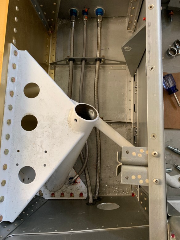
The next dilemma was to figure out how to route my return line under the seats and more specifically where to drill a 2nd hole in the side skins for its exit to the wing tanks. I went with the brake lines in the middle tunnel fitting and fuel lines on the outside. The supply goes on the forward (right as shown here) fitting per plans, and the return goes in the aft location (left as shown here). As you can see, the white gear weldment gets in the way of a straight shot out to the side skins. One must route the return line forward a little bit around the gear weldment, but also avoiding interference with the brake line. I can certainly see why some people chose to route the brake line in the aft location and the fuel lines in the middle and forward position. It was at this point that I solicited some opinions on VAF and also stepped back and looked at pictures of the area between the fuselage and the wing tanks to help guide my decision. Best to step back and do some research prior to drilling holes in the side of the plane willy nilly.
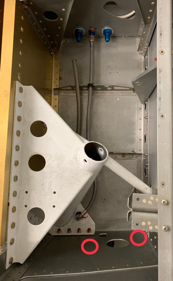
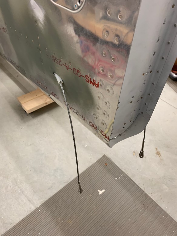
Two proposed areas for a hole on the side skins marked by red circles.
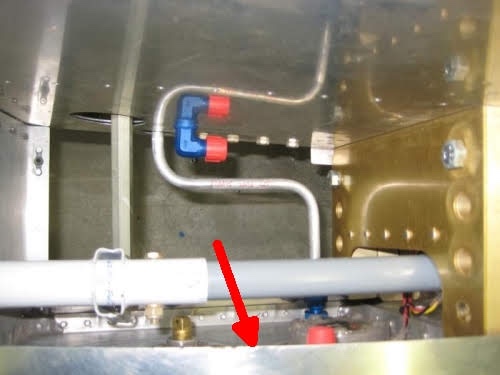
The following picture I stole from another builder. It depicts the area in question. On top, is the side skin of the fuselage. Forward is on the left. Bottom is the fuel tank. Here you can see the hard fuel supply line coming out of the stock hole in the fuselage at the top, bending right and downward into the tank fitting. The red arrow indicates the approximate position of my return fitting on the tank. It’s just forward of the tank vent which has a red cap or tape on it in this picture just to the right of the arrow. One thing that I noticed is that if I were to drill a hole in the most-forward position indicated on the picture above, I might interfere with the aileron control rod or interfere with the tank attach bracket (the medal piece all the way to the left in the picture.) So I decided to keep it close to the supply line in a very similar spot as this builder did. His return line is the blue 90* AN fitting just above and behind the supply line.
This is what I ended up with. I won’t really know for sure how well the hose with a 90* end will work until much later on in the build. At least not until I test fit my wings.
Then it was securing the lines to the system control brackets. This required a little dremmeling to open them up a bit more to accommodate the larger diameter lines. The return line passes under the brake line on its way out. There is a little air gap between them, but I’ll probably wrap some spiral separator on one of them to avoid any rubbing via vibration.
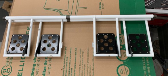
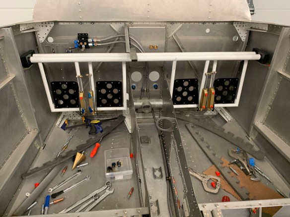
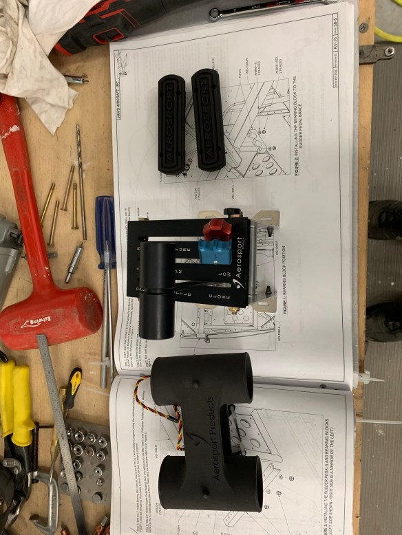
So while waiting for Tom to get back from vacation and help with the custom hose lenghts for the 2 hoses remaining, I went back and finished up the rudder section of the plans. This section is also pretty easy. Just a matter of bolting the pedal assembly in place and routing the lines.

The final part of this section is to run the rudder cables and connect them up to the rudder assembly.
Cable ends that’ll connect to the rudder itself

Adel clamps in tail holding the plastic sleeves in place
Cable routing through tailcone

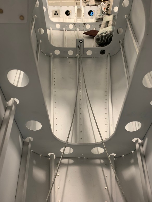
Cable routing through tunnel in fuselage

Rudder cable attached to rudder
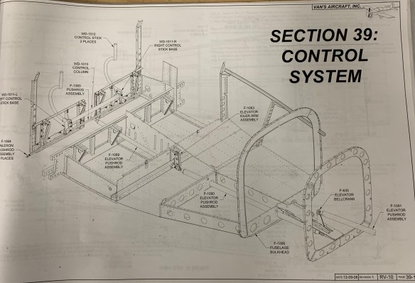
Now it’s on to section 39, the control system. Control sticks and pushrods will be installed in this section.