Lower instrument console and armrest

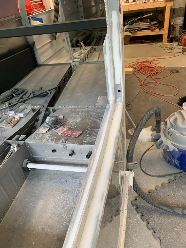
Prior to starting to wire all the FWF stuff, I decided to get my lower console with its side panels and the center armrest with the fuel selector and throttle quadrant installed. The main reason for this, is I need to measure for my throttle and prop cable lengths and I can’t do that with out placing the quadrant.

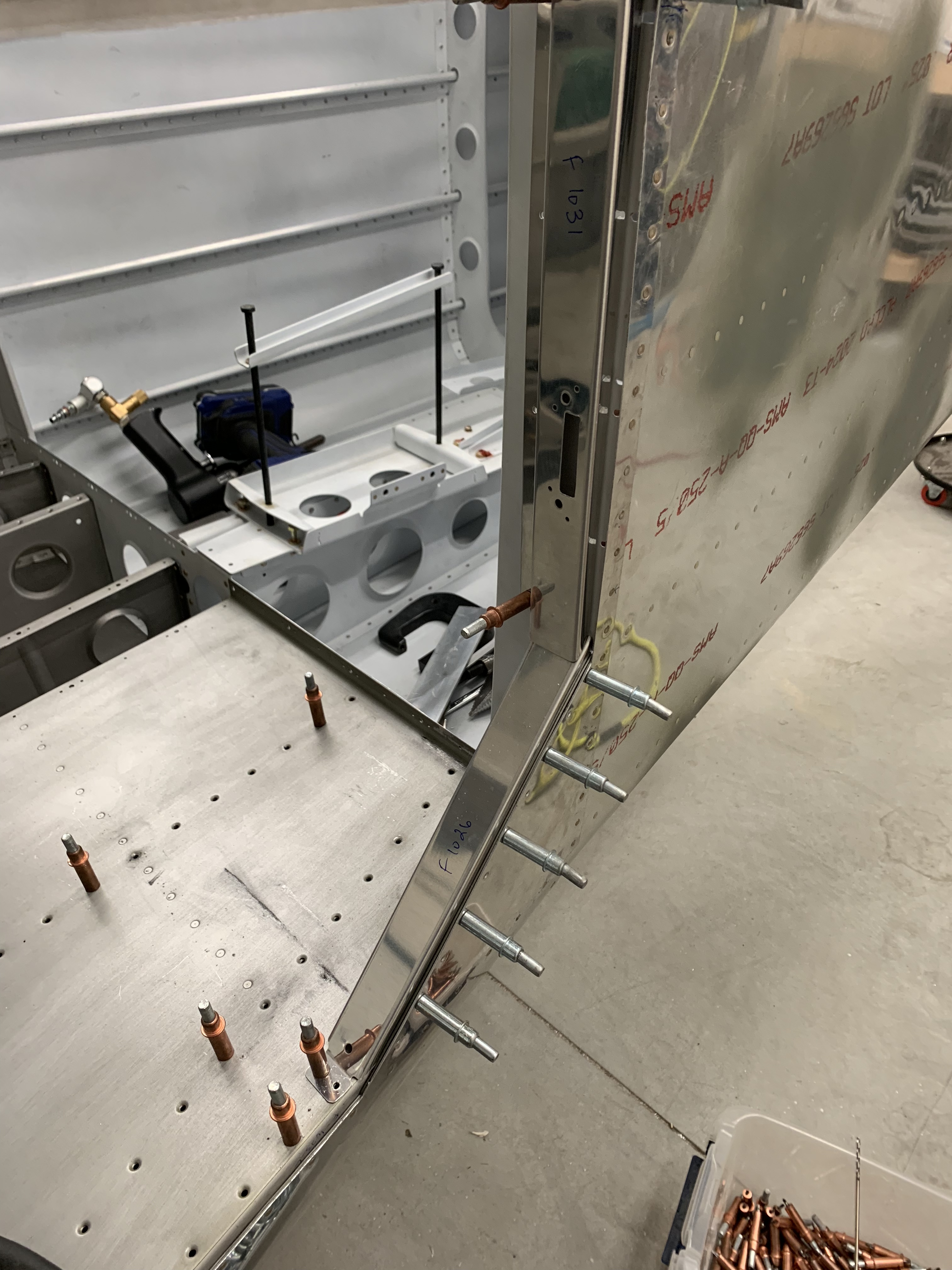
I first mounted the lower instrument panel console and got it match drilled to the left side panel. The same was done to the right side panel. I used a strap duplicator to match drill holes into the side panels along the top of the tunnel so we can secure them to the existing hole/nutplate locations. Once that was done, I located the center armrest into position and matched drilled 6 holes (3 per side) also to the existing screw holes on the top of the tunnel.

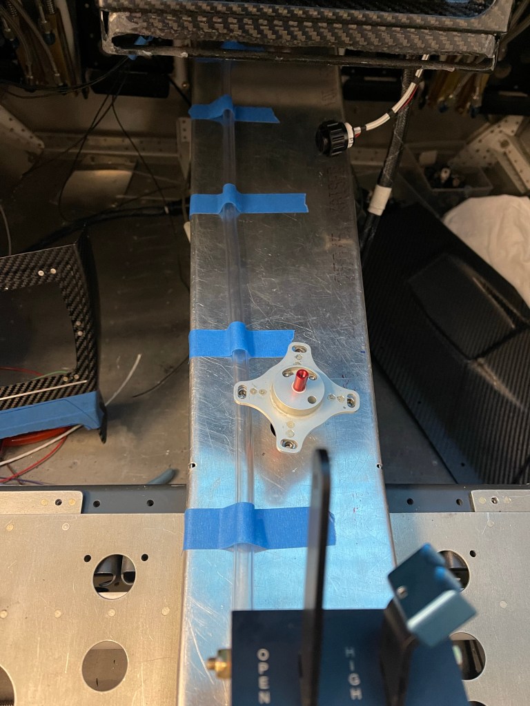
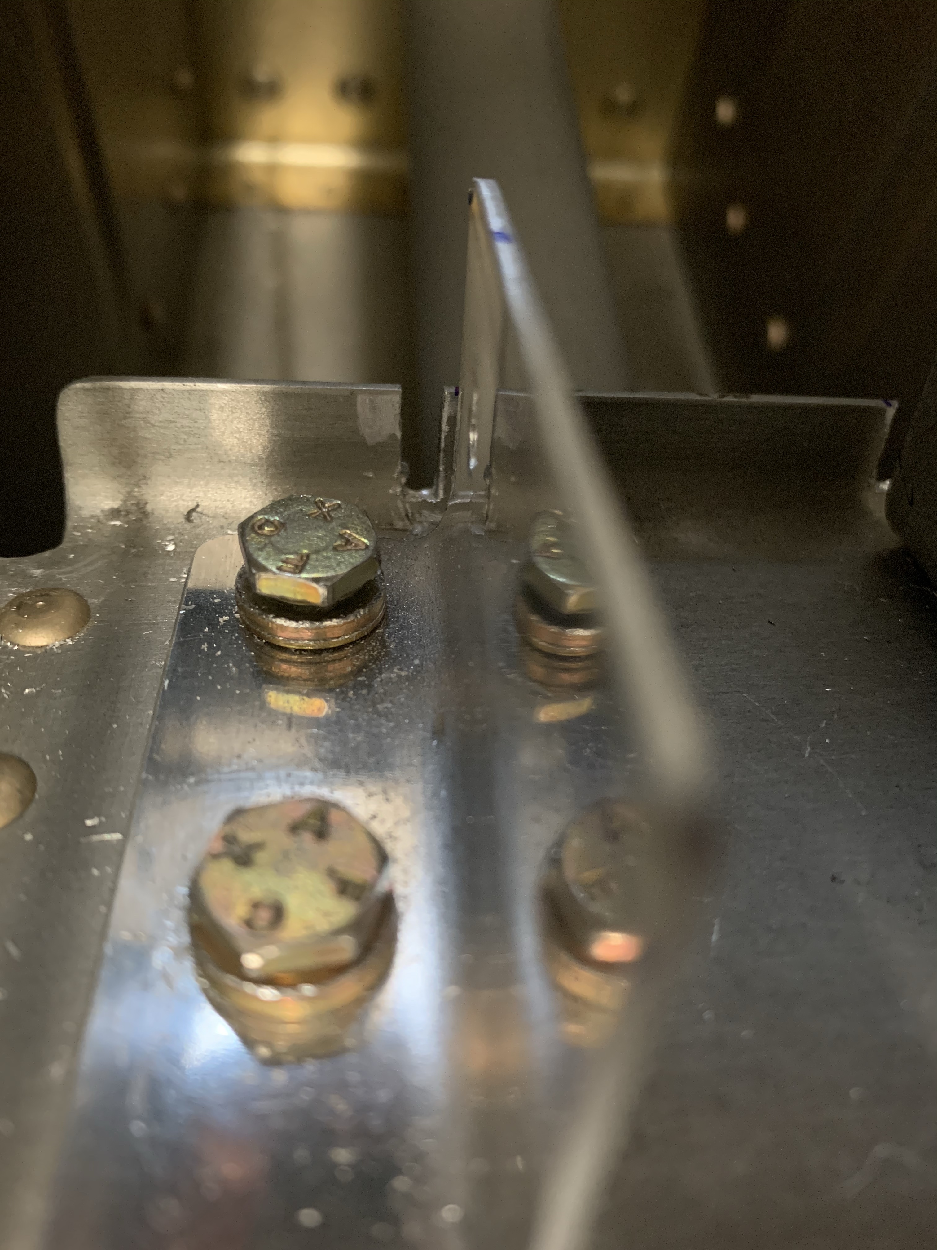
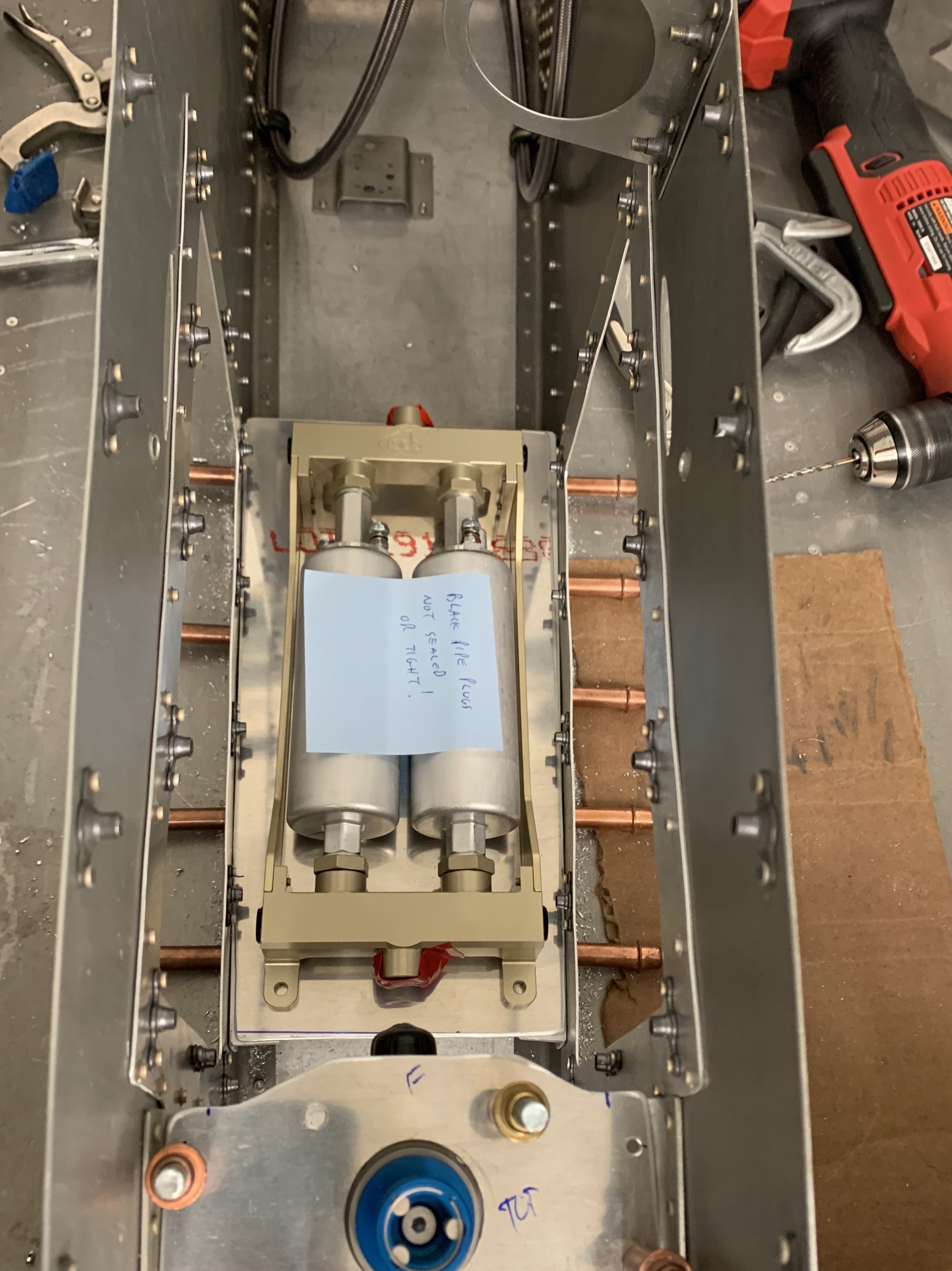
I then cut out the armrest for the throttle quadrant based on the scribe lines. I placed the quadrant into rough position in the armrest while it was upside down and taped it down. I placed masking tape down on the tunnel cover approx. where the quadrant will sit. Then with the center armrest placed down and screwed to the tunnel cover, I marked the legs of the quadrant on the masking tape through the top opening of the armrest. I then removed everything and drilled holes and bolted the quadrant to the tunnel cover. The holes are slotted, so you have some fore/aft as well as up/down adjustment. Getting it pretty close was sufficient. The harder adjustment was the up/down as you don’t have access to the screws with the armrest in place.

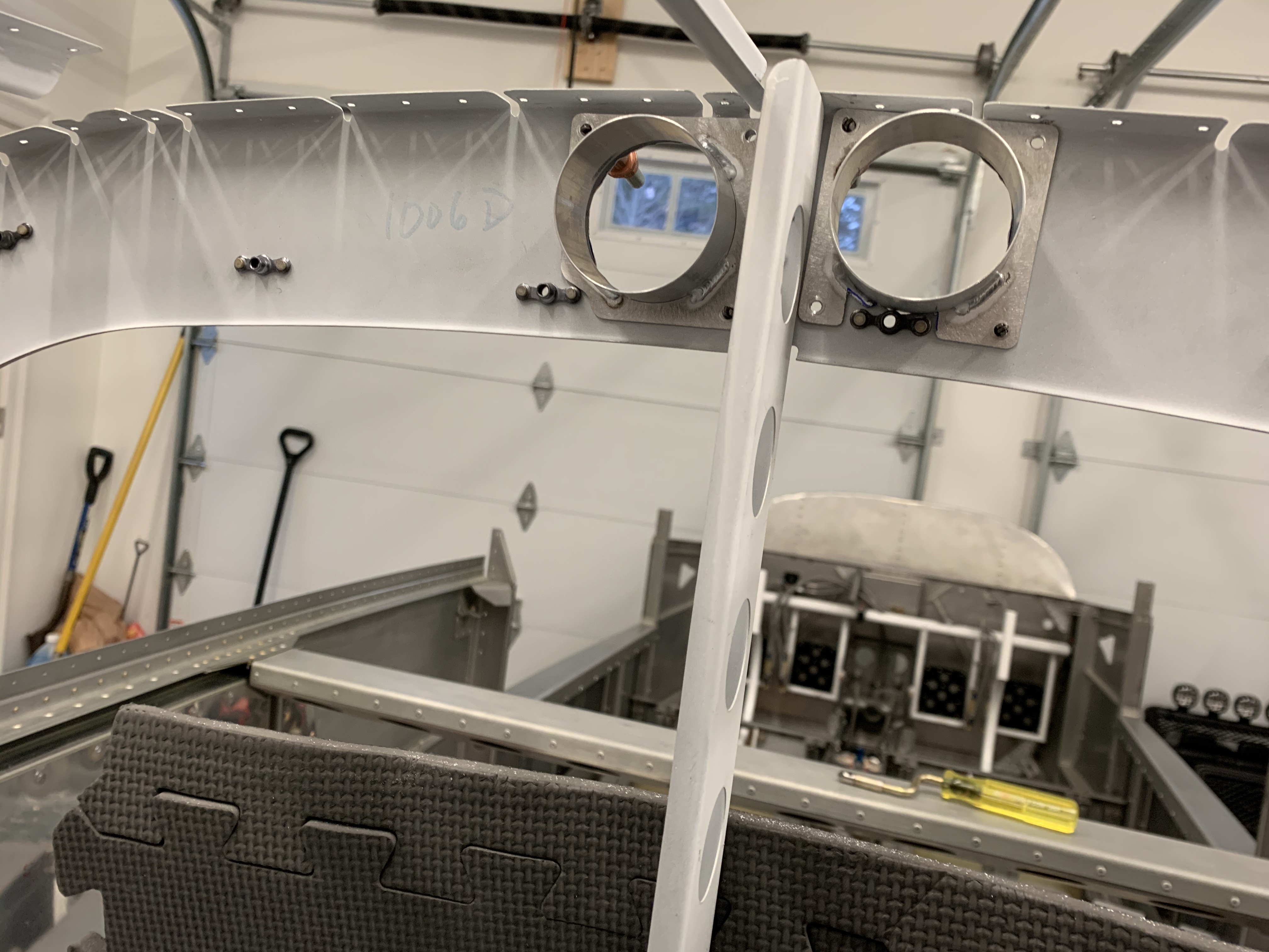
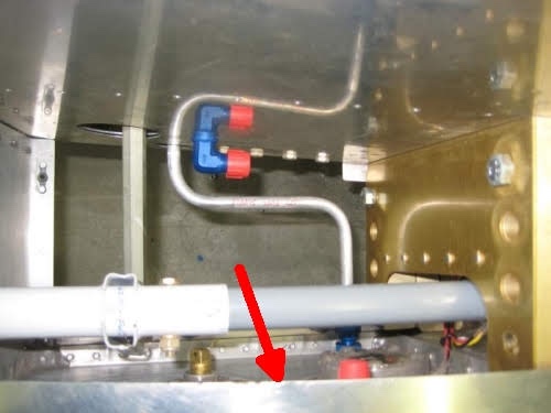
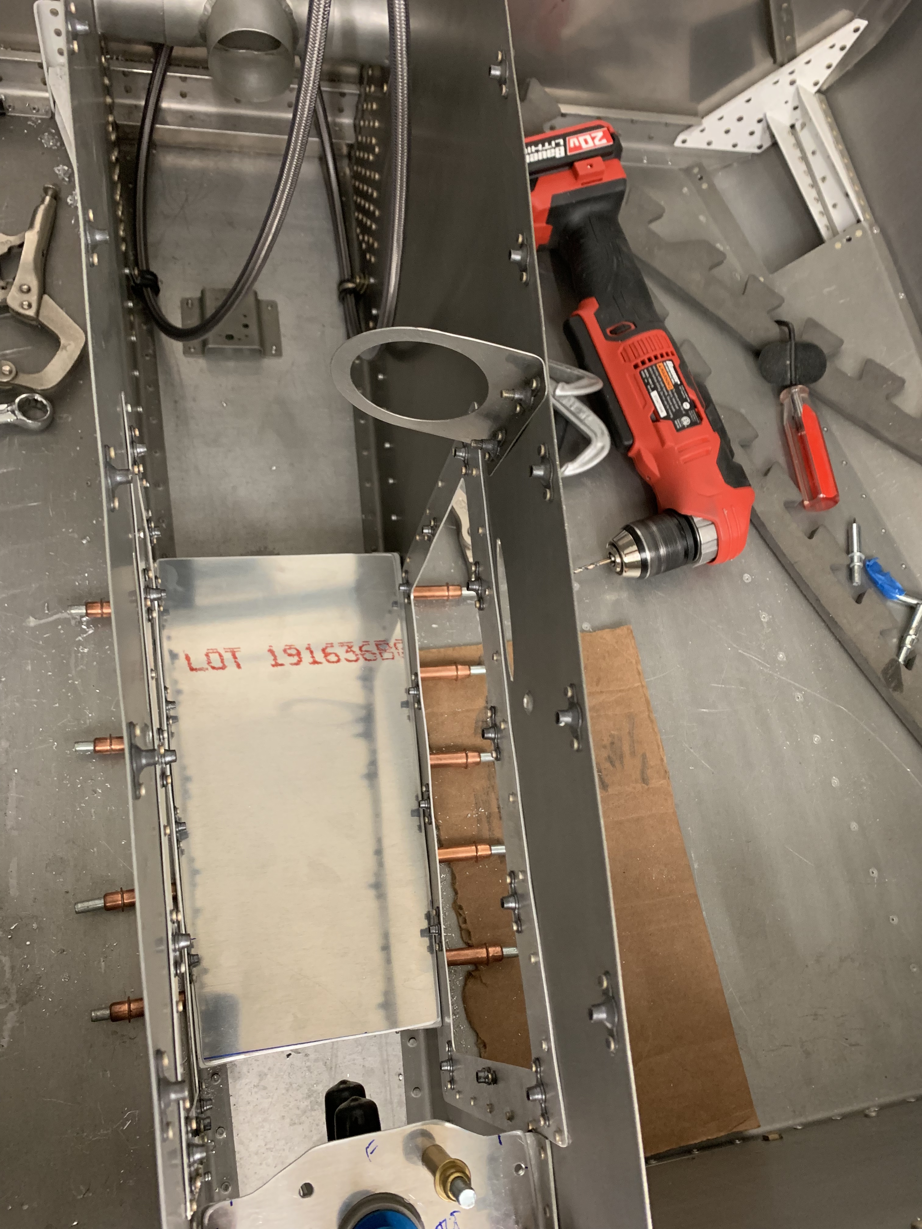
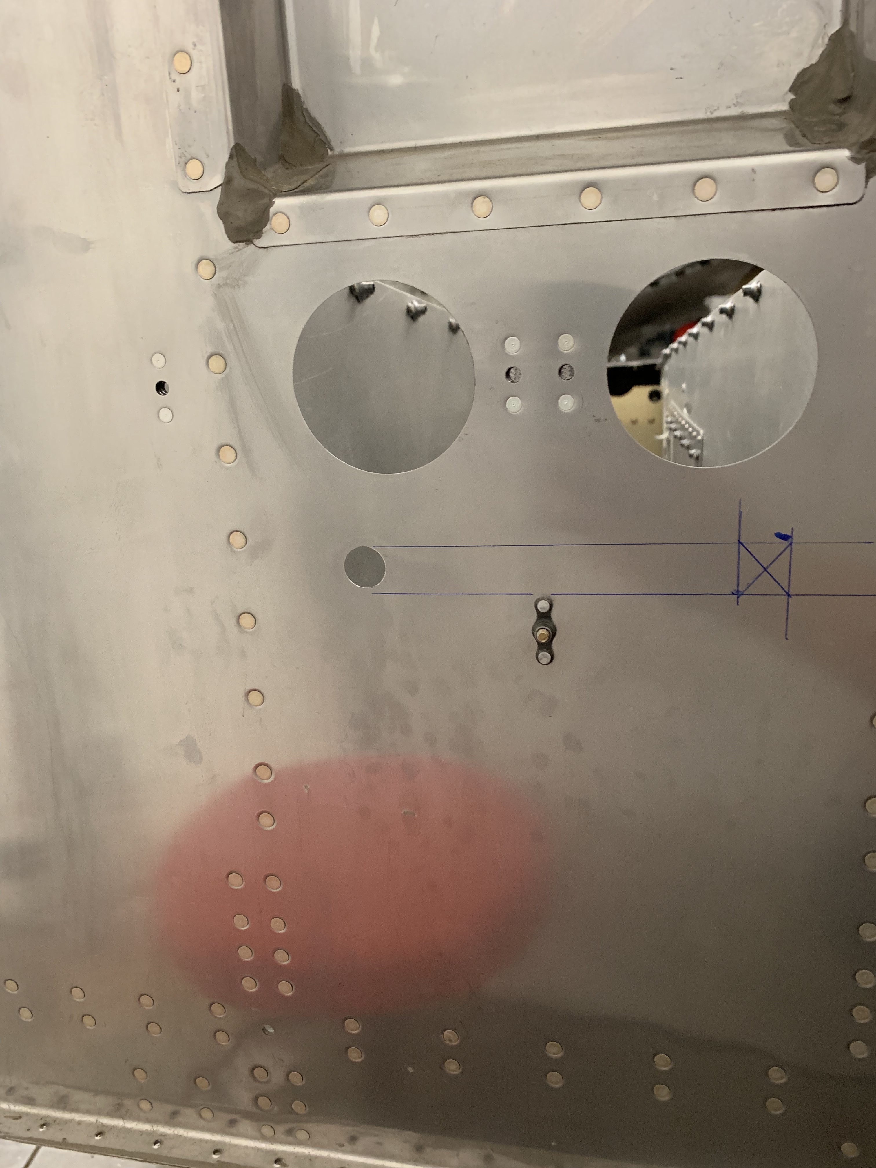
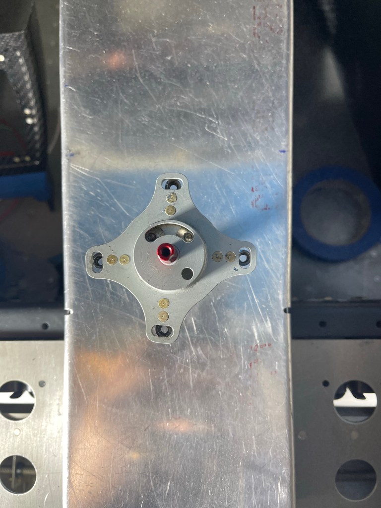
Once that was done, I had previously placed the Andair selector valve more or less in the stock location. So I drilled the hole provided by Van’s up to 3/4″ round hole for the Andair extension arm to come up through the tunnel cover. The extension was pretty close to centered on that hole, so I left it as is.. I used that hole in the tunnel cover to locate and drill the hole in the carbon armrest for the selector.

Throttle quadrant and fuel selector valve hole cut

Then the extension arm was cut to the proper length following the Andair instructions and the bottom part of the selector was placed onto the arm and test fit to the hole in the armrest.

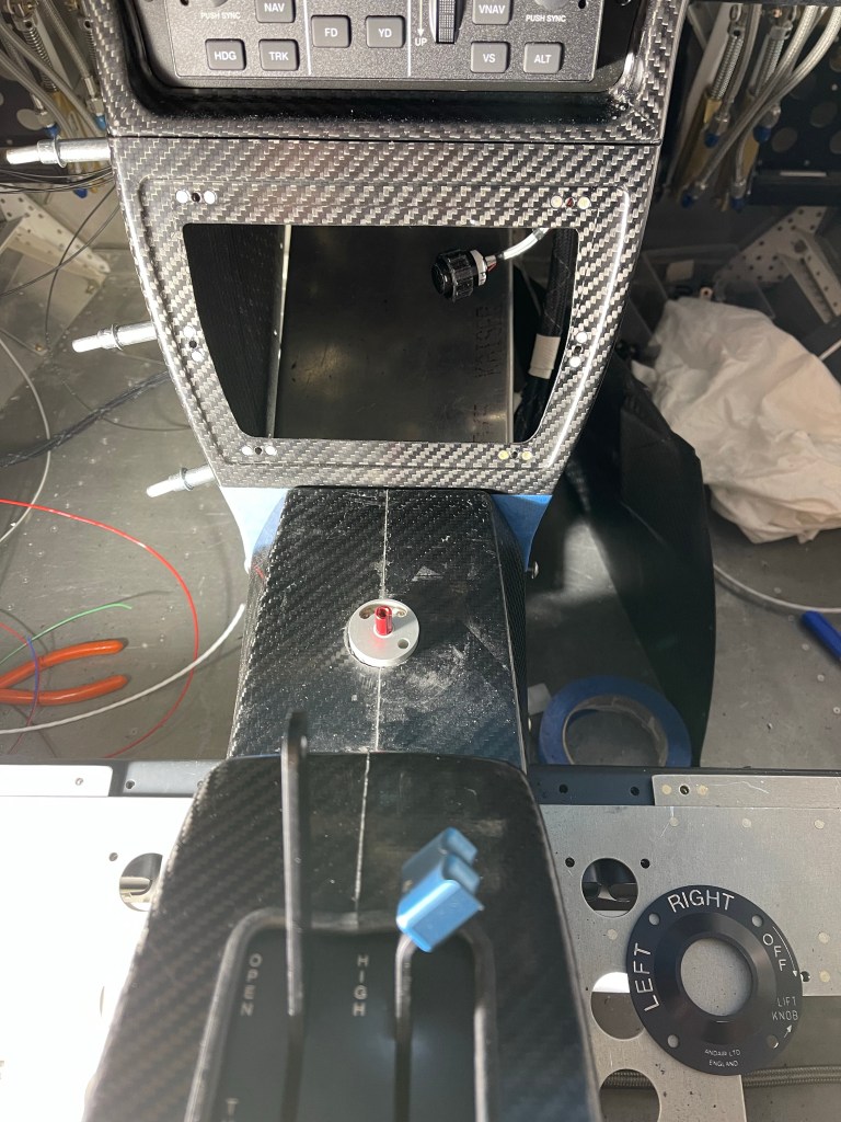
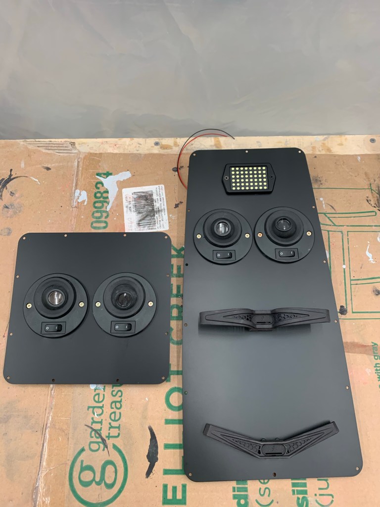
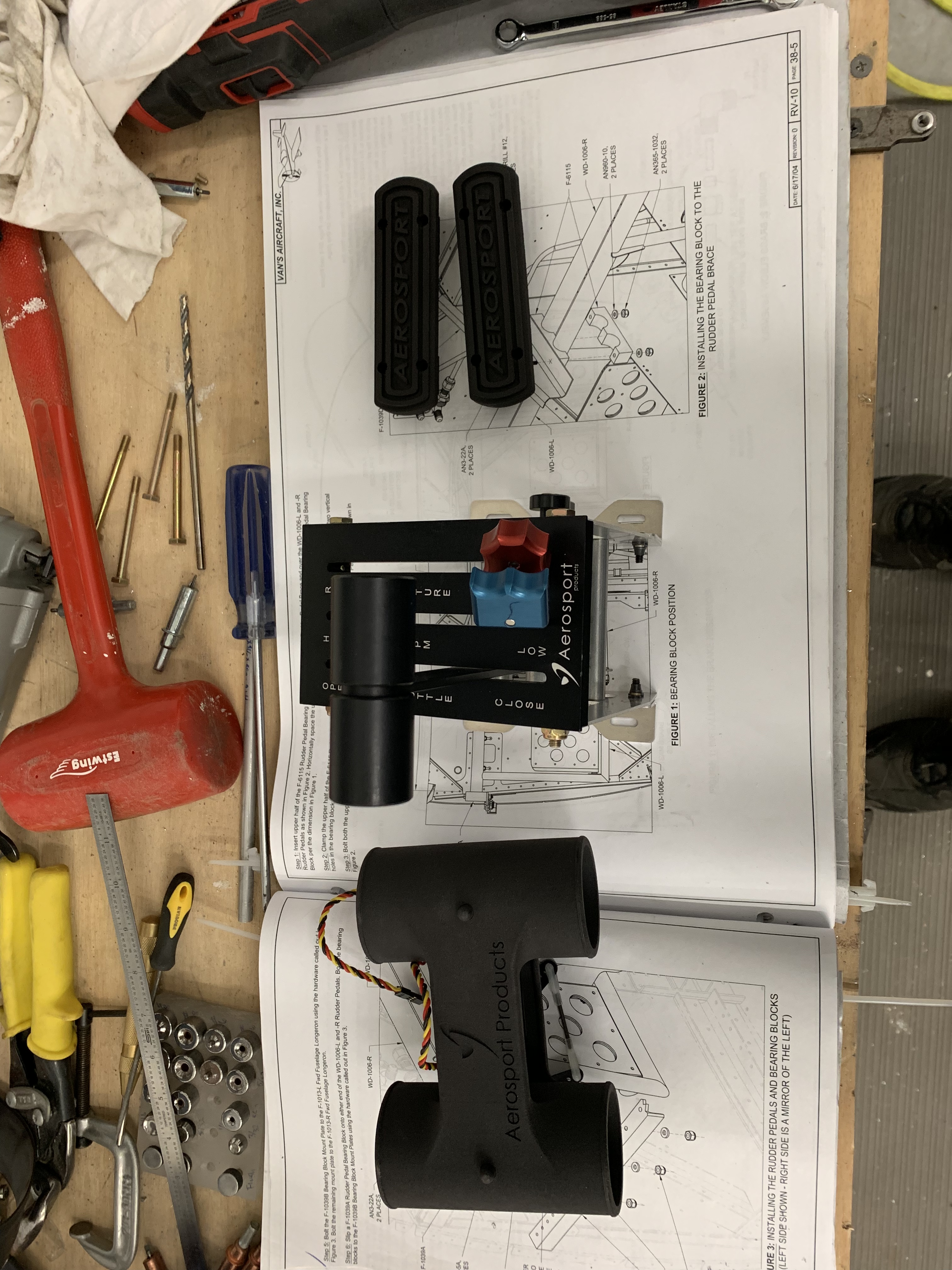
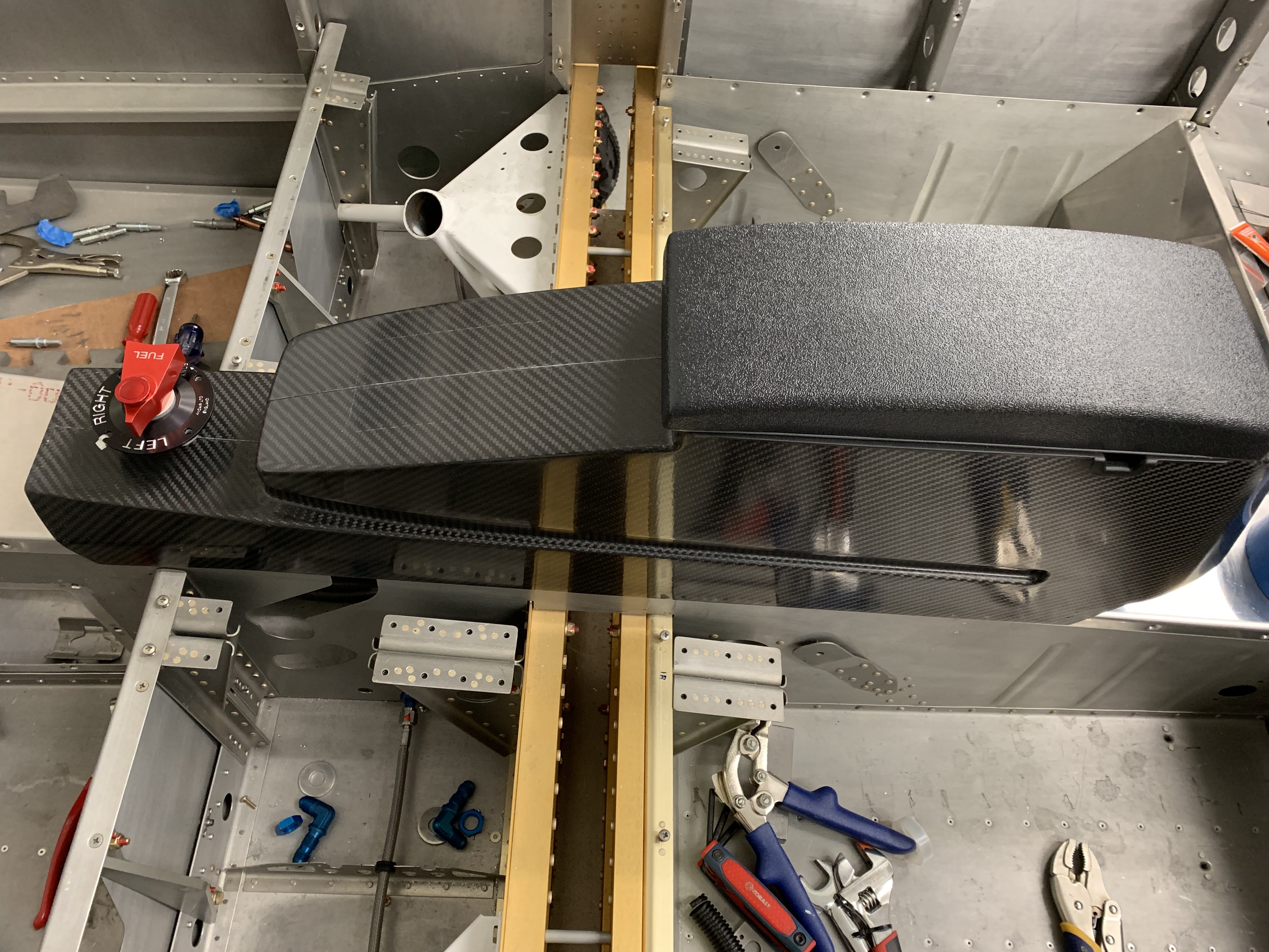
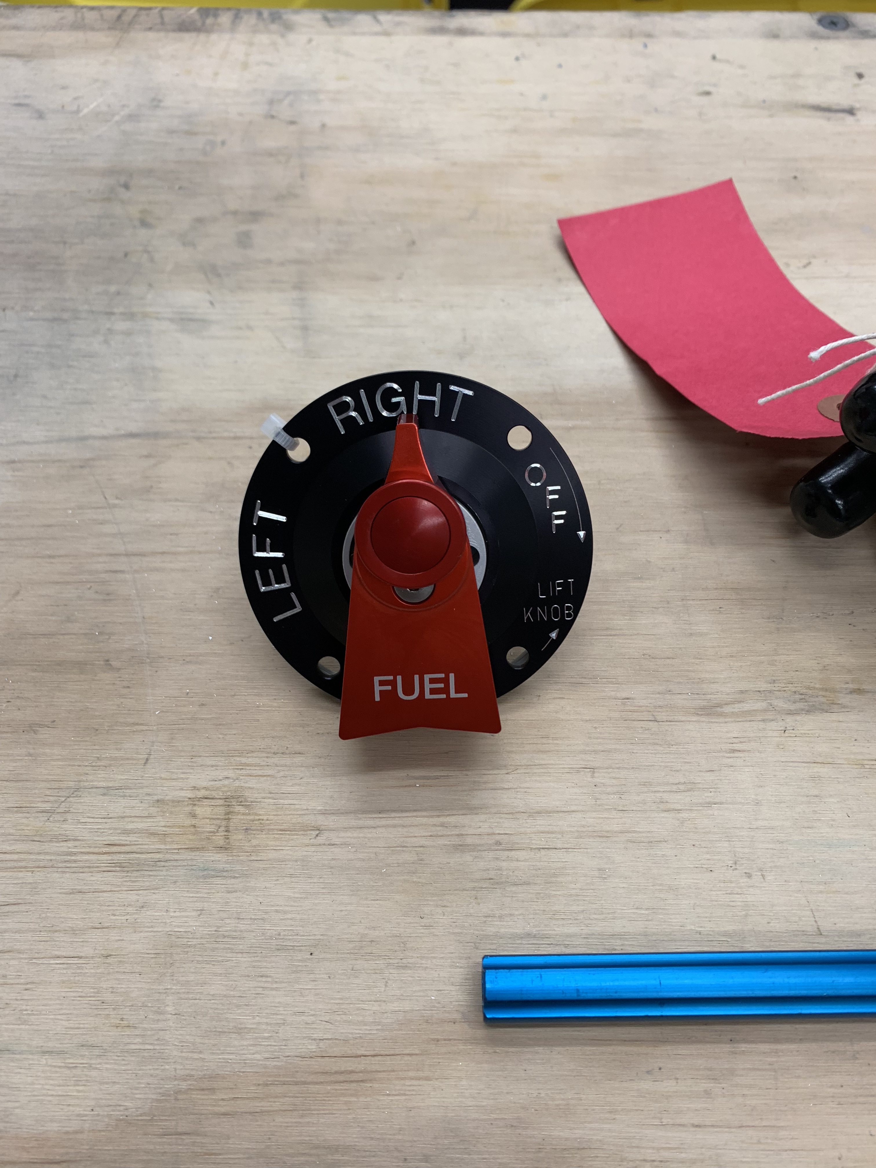
The faceplate was put into position and I used the 4 screw holes on it to drill holes into the armrest. I prefer the orientation to be as shown below. I feel like it’s a little more clear this way as the selector will be pointing left and right for selecting the respective tank. Mounting the faceplate so that the “Lift knob” is right reading, so to speak, would have left tank selection pointing really left and right tank selection still pointing left, just not as much.

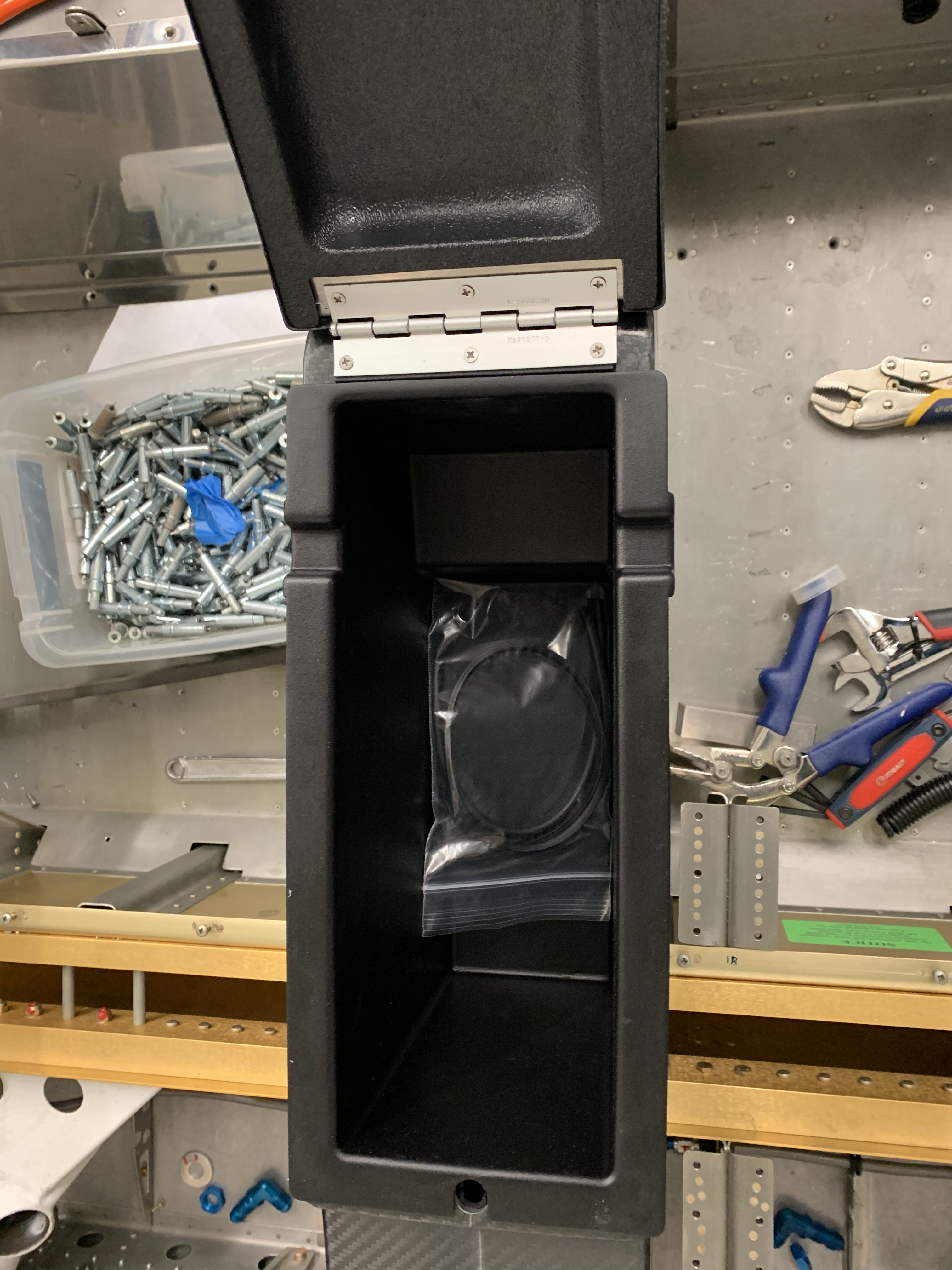
In order to be able to potentially remove the center armrest without removing the lower console nor the fuel selector valve, I used nutplates on the piece that sits under the selector valve as shown below. A couple of the holes on the armrest has to be oblonged a little bit to make the screws meet the nutplates properly, but that isn’t a big deal as the faceplate covers that area.

Nutplates on face plate screwdown plate

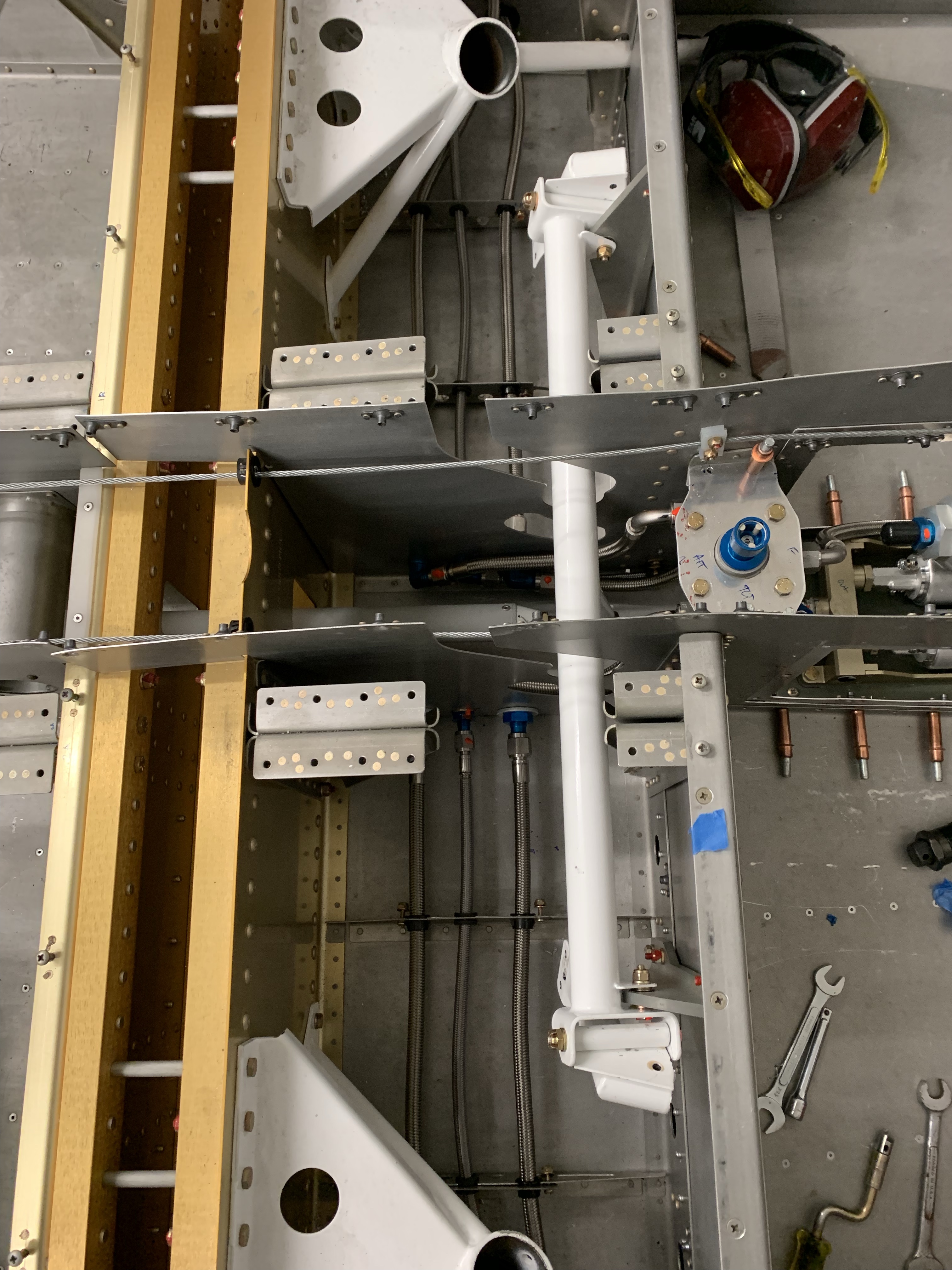
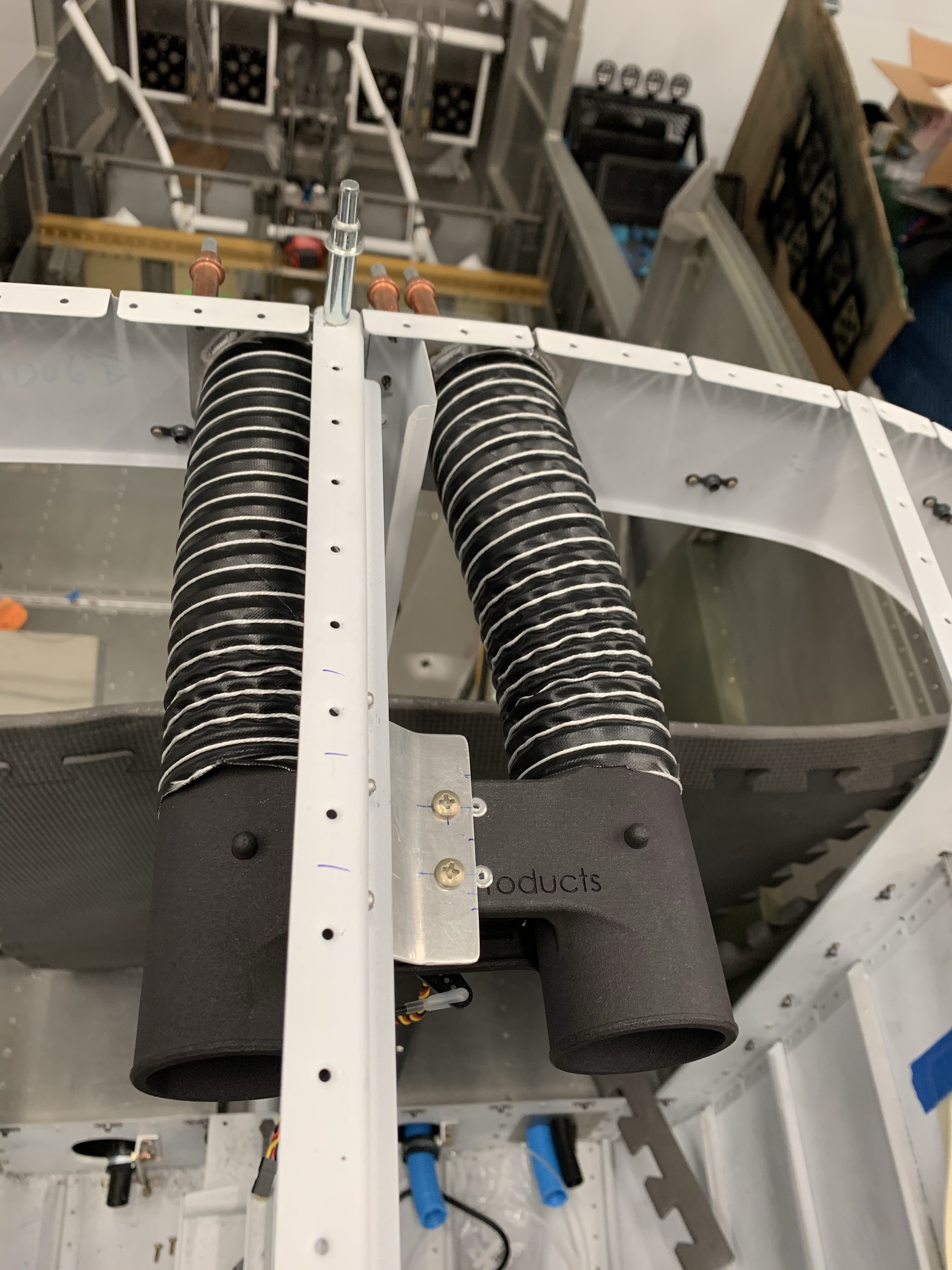
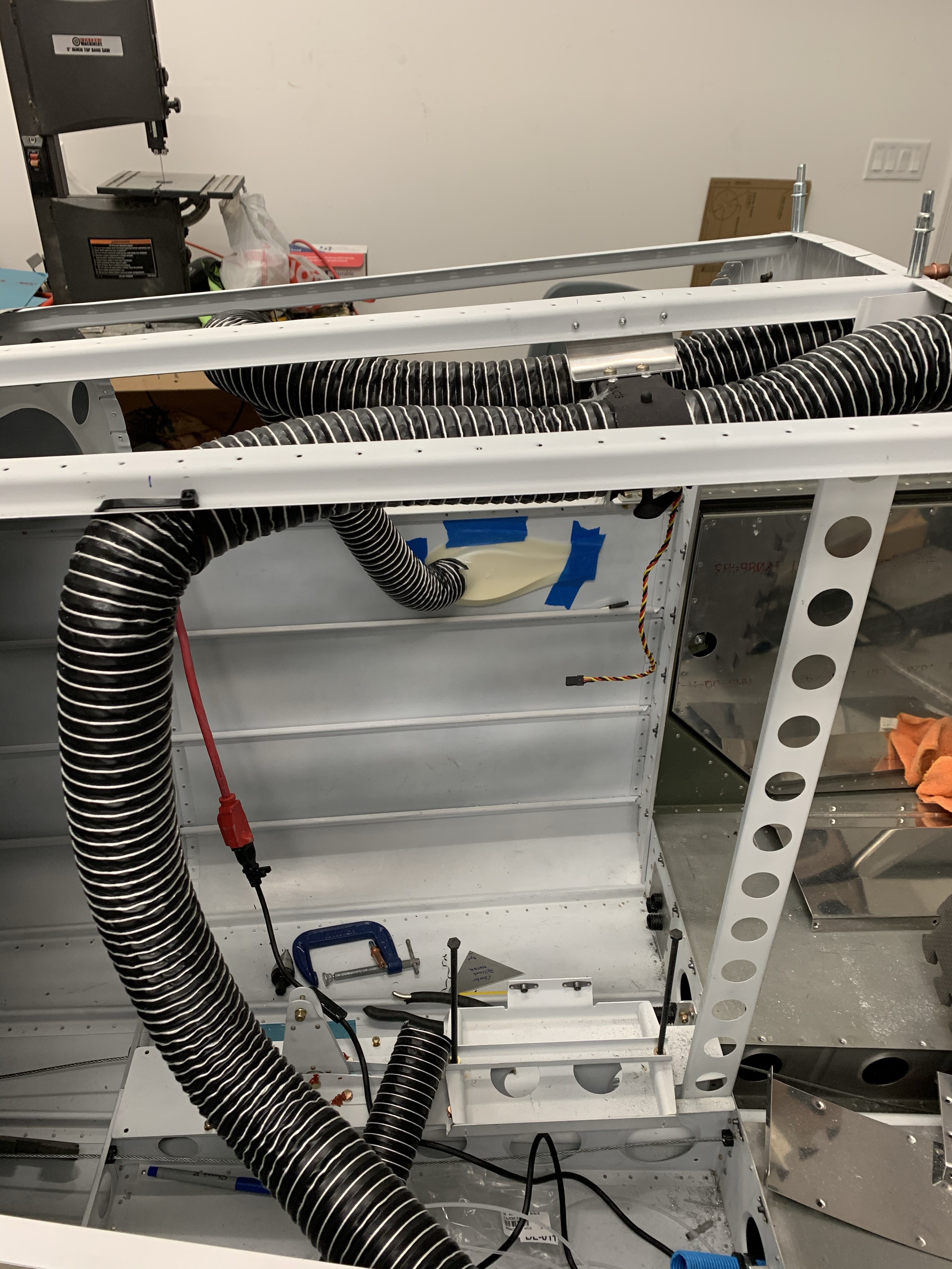
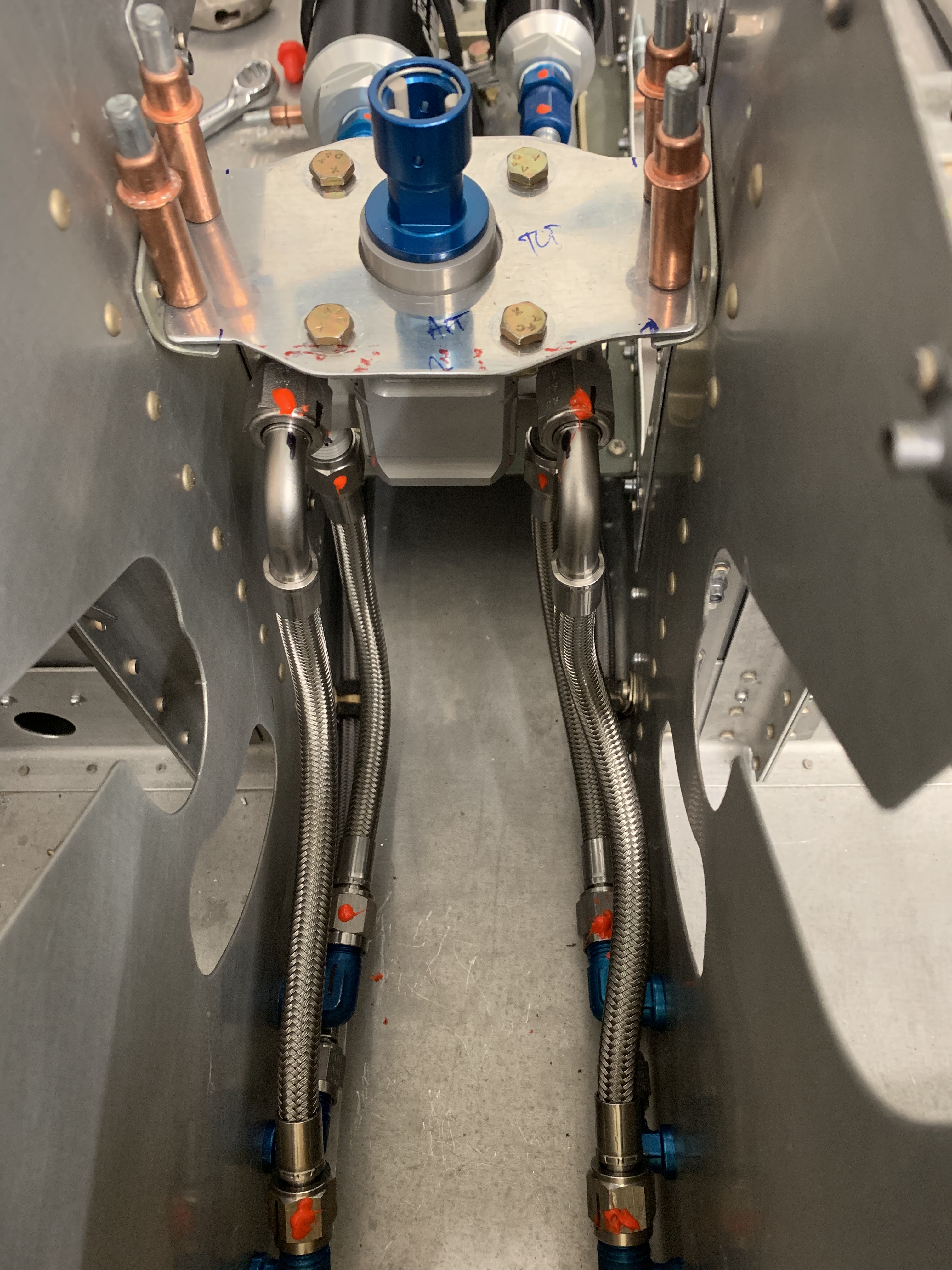
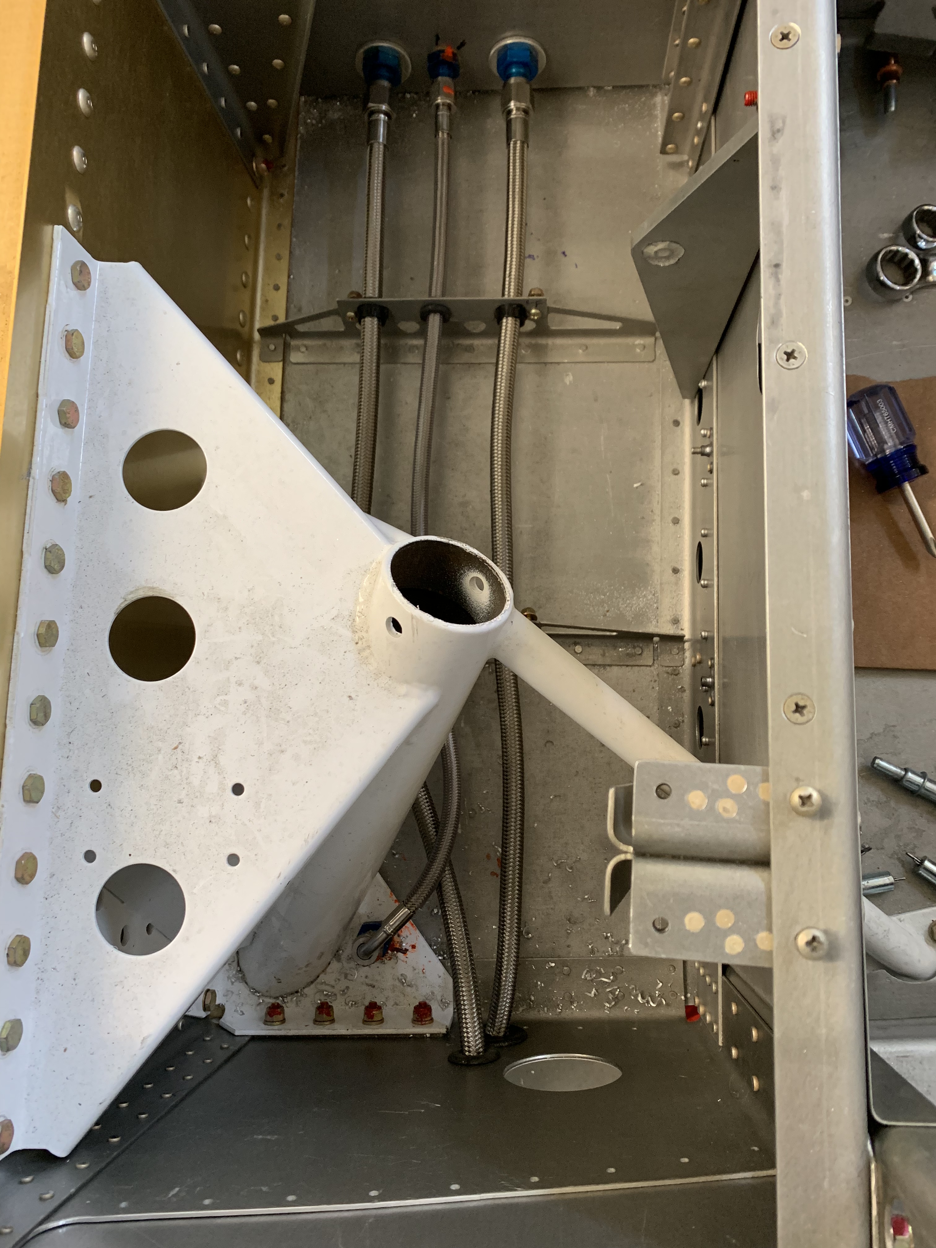
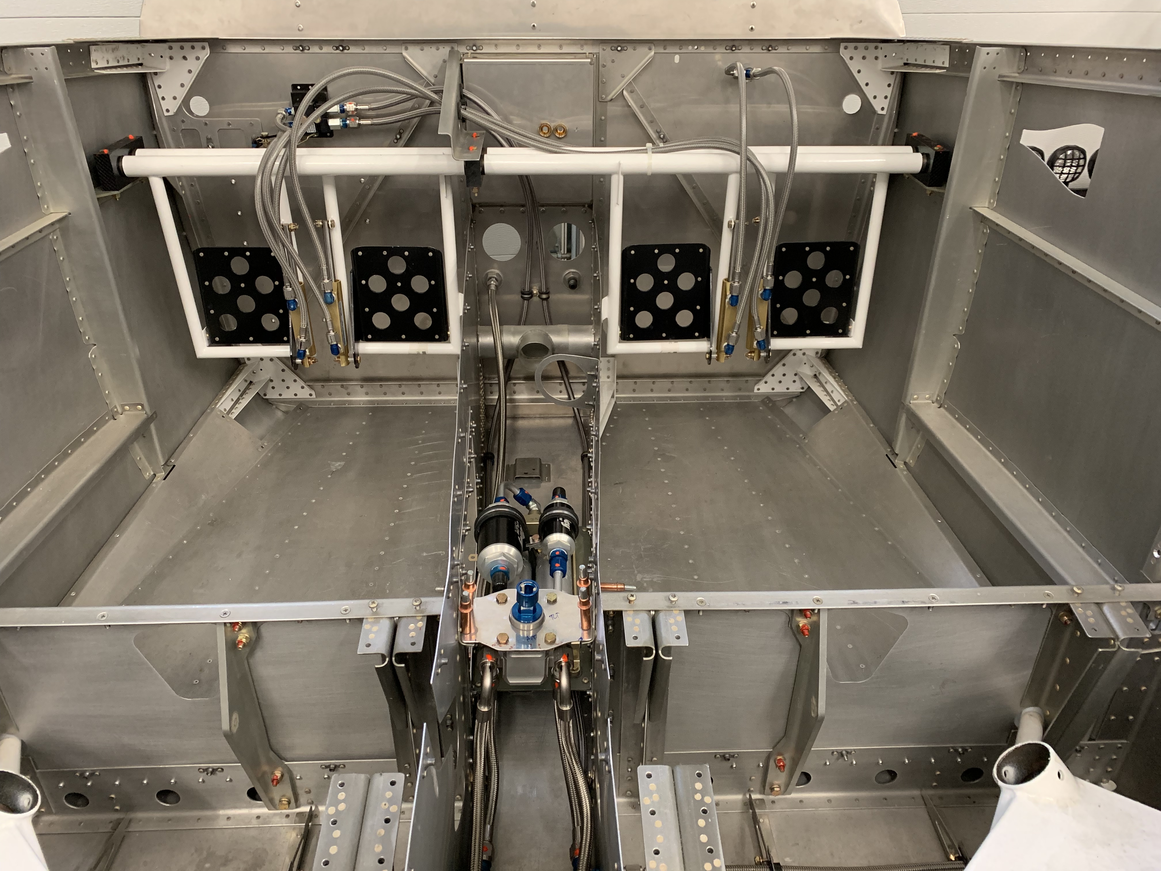
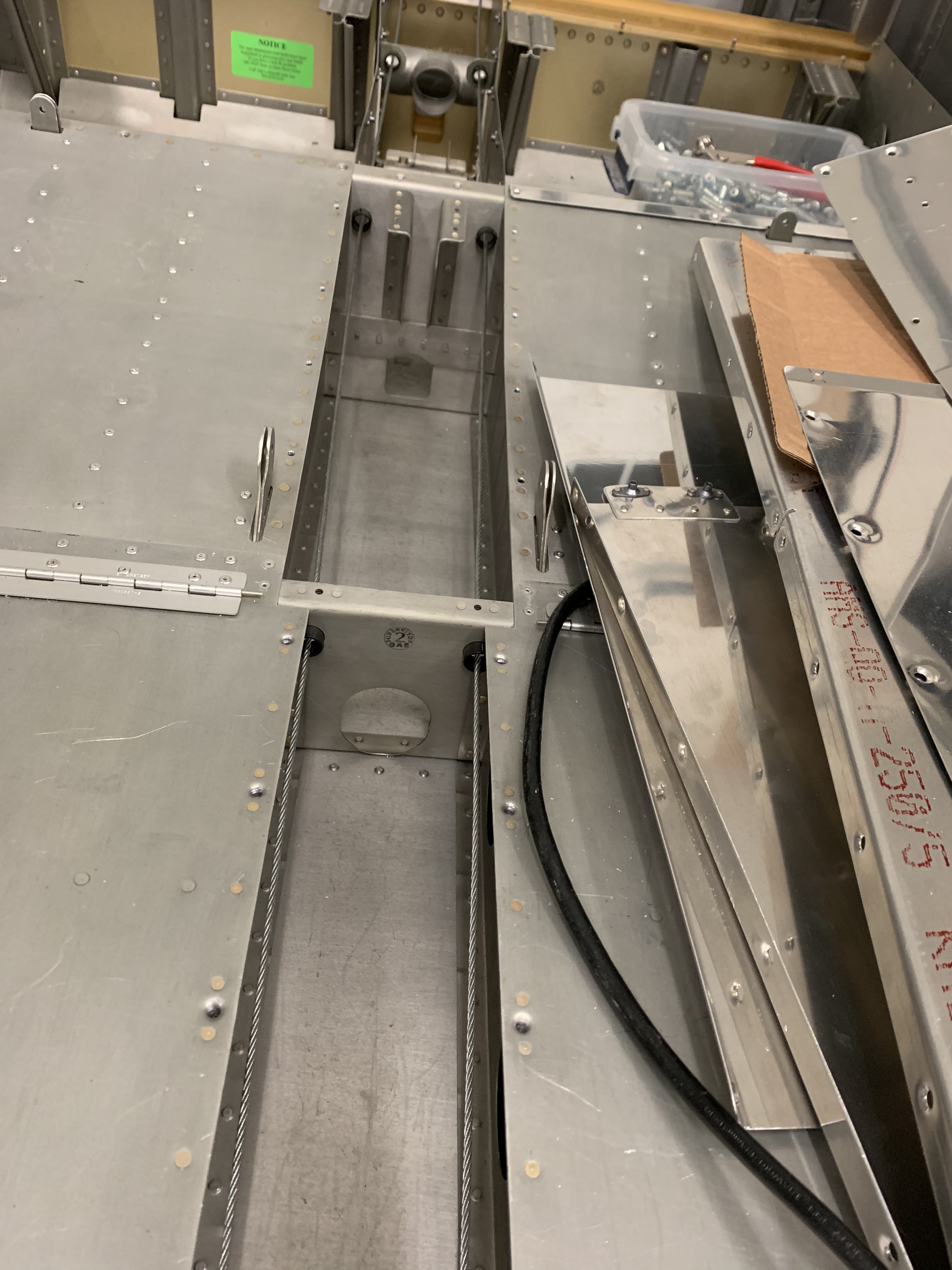
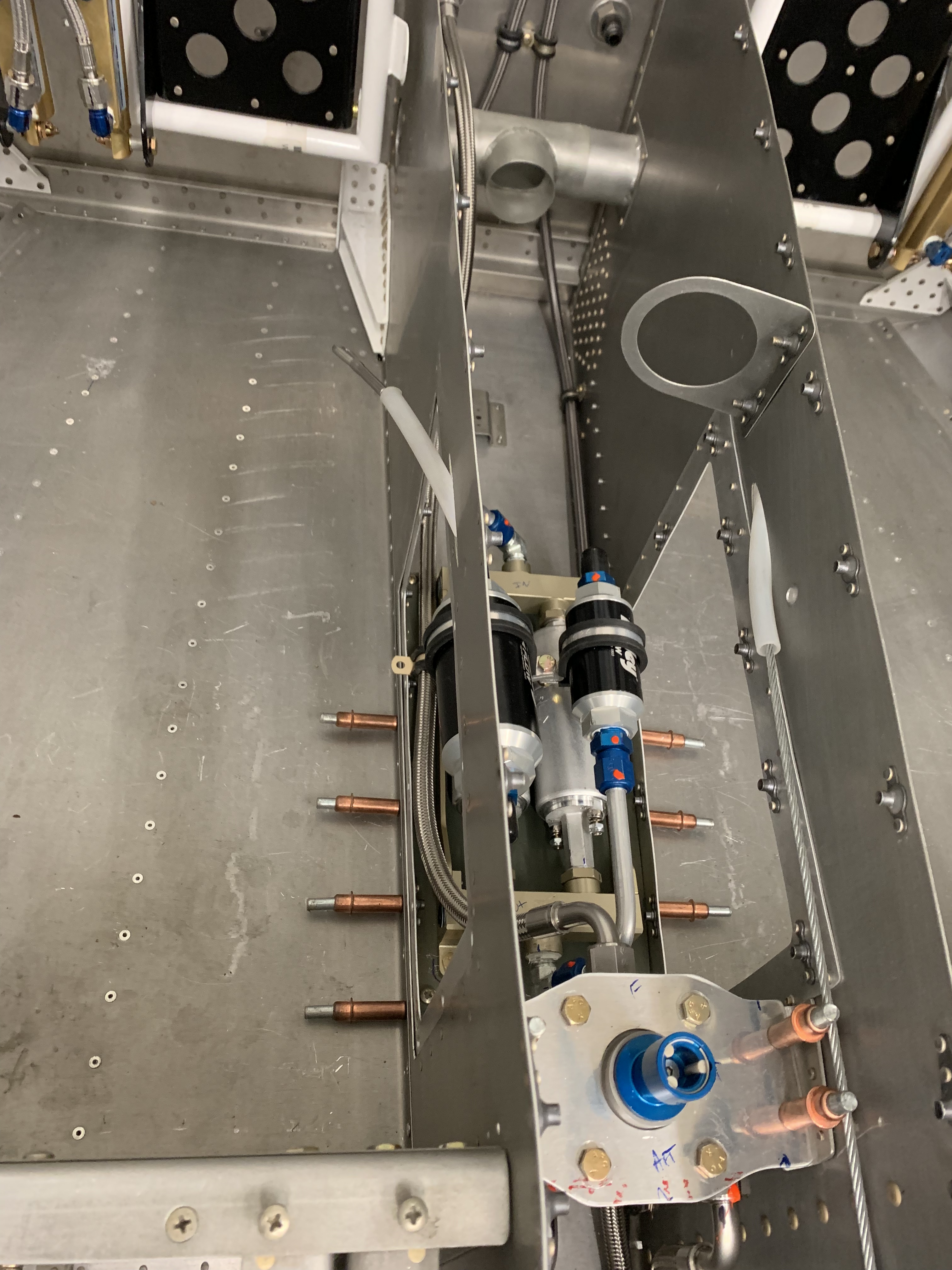
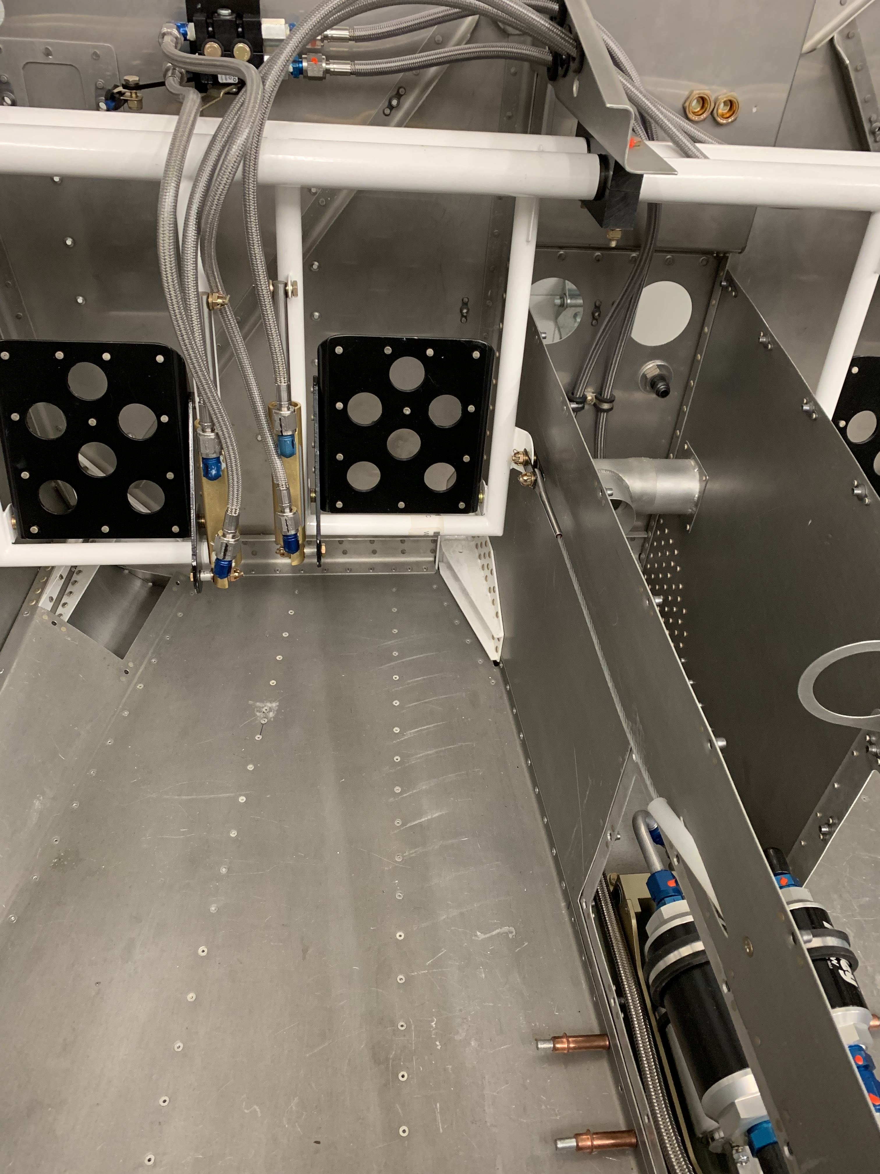
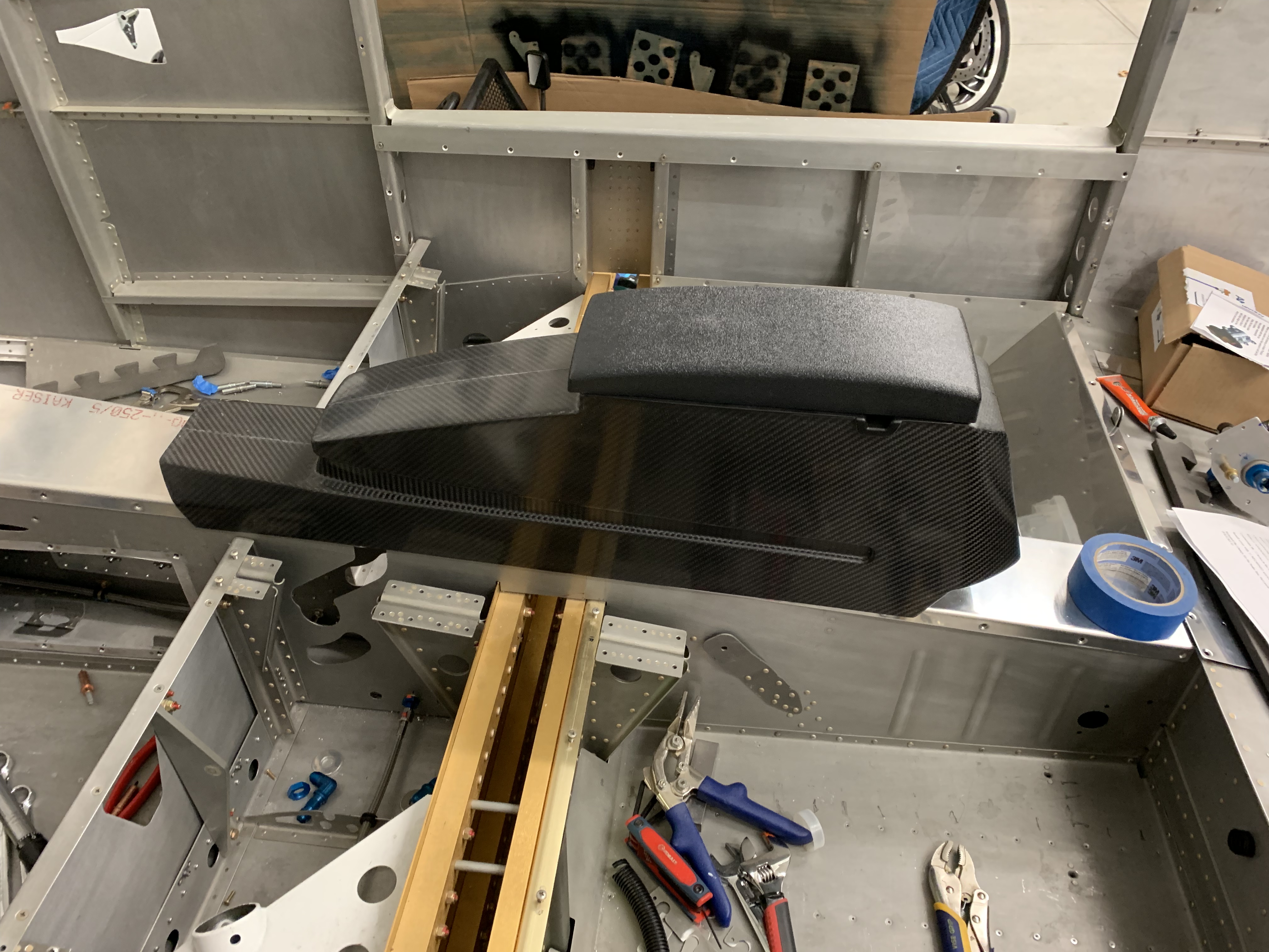
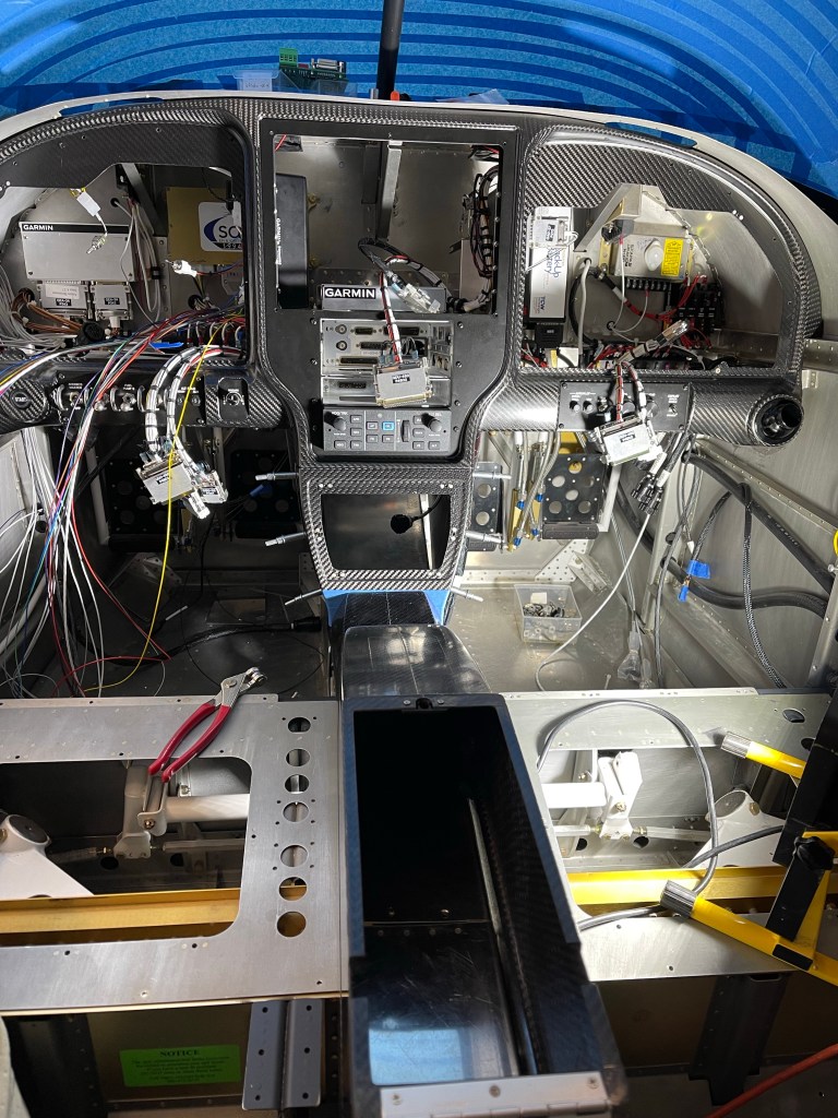
With all that done, below are the end result at various angles.

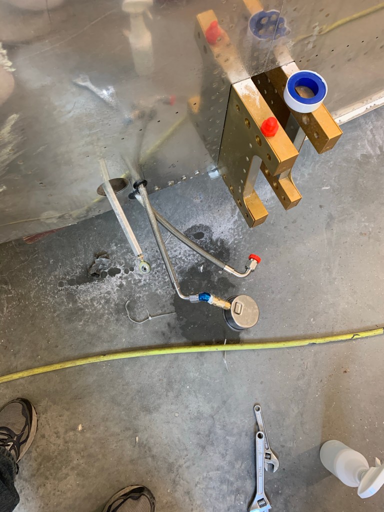
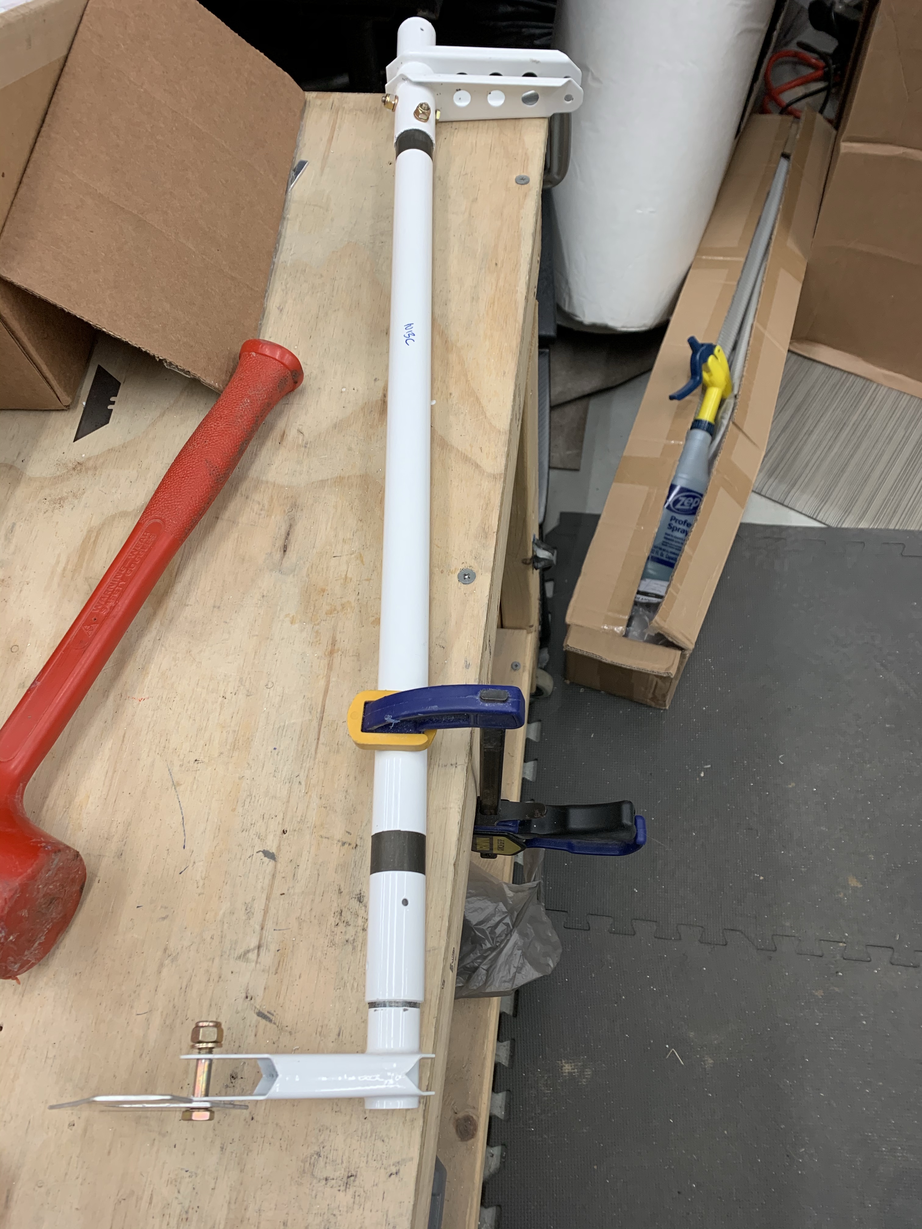
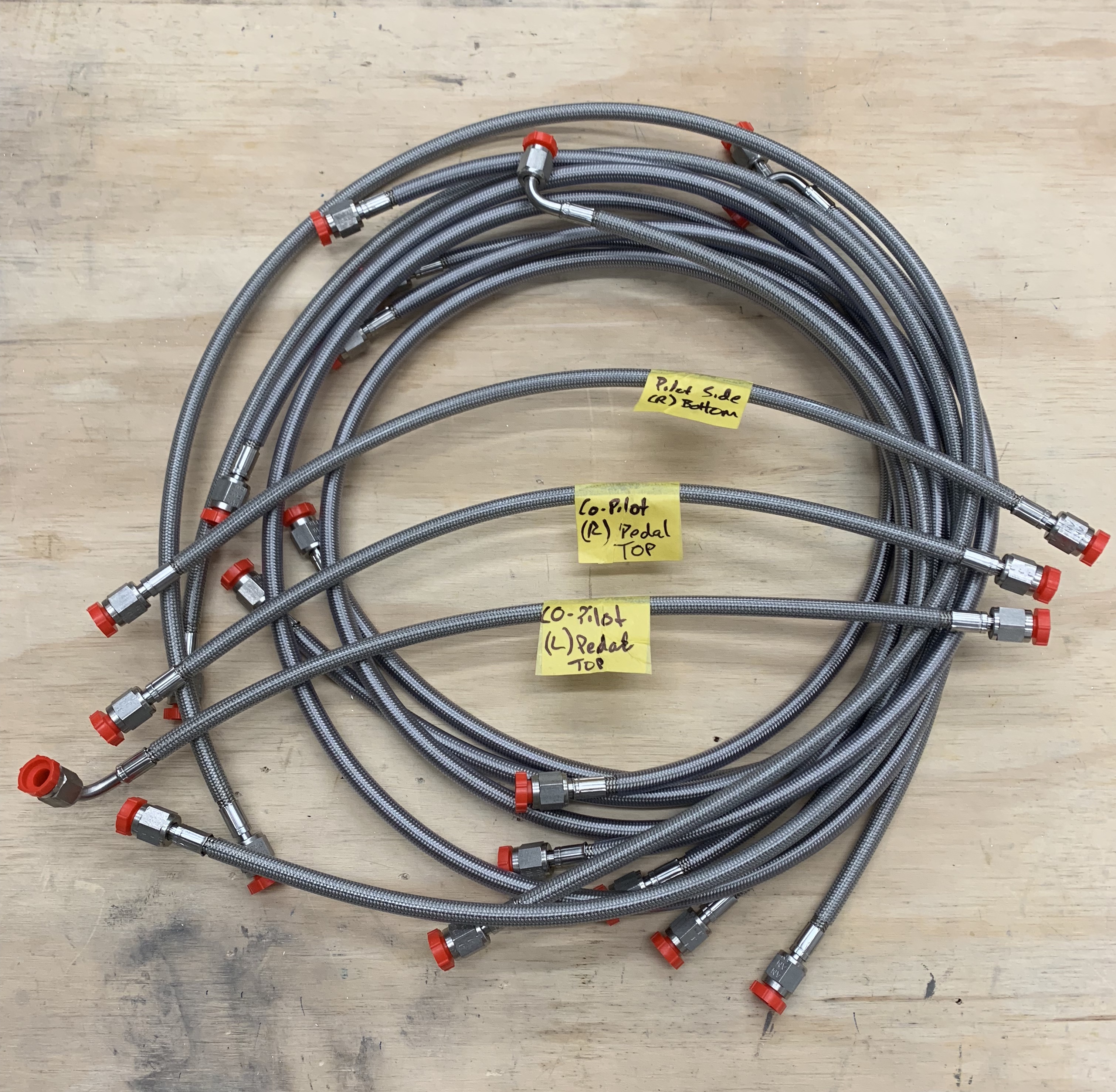
I was then able to measure for my cable lengths. I used some vinyl tubing I had lying around to emulate the route for both the throttle and prop cables. I marked around the mid point of the threaded part of the bearing/tie rod terminals and made sure the controls were both full deflection in the same direction (fwd/fwd or aft/aft), I then pulled the tubing out and measured the marks. I did add a couple of inches for some slop or slight variations in the install path that I measured to.

Fuel filter/cabin line redo plus FWF plumbing starts

Back when I installed my fuel lines, Tom from AS Flightlines ( http://www.aircraftspecialty.com) really only had one solution to the SDS fuel filters. On top of the fuel pump module using adel clamps. I really don’t like having these in the tunnel for maintenance reasons. It seems inevitable that some amount of fuel will spill out into the tunnel no matter how careful I am trying to catch it all as I take this all apart for yearly service. Additionally, I placed the access panels on the tunnel sidewalls a little further aft and not perfectly aligned to the whole assembly, so access to the forward-most fittings is a bit challenging. Taking the top of the tunnel off, while doable, is a royal pain seeing there are throttle cables, etc.. routed on top of that. I really have always viewed this solution as something I’m going to regret and will spend way more time than I really should on each condition inspection. Also I can envision lots of curse words being used. Below is a view of the original filter setup in the tunnel.

Original tunnel fuel filter arrangement.

Since that time, Tom has come up with pre-filters in the wing roots, and moving the post filter firewall forward. Despite having some re-do.. I opted to take some time now to change and use this new configuration. Maintenance will be much easier and more accessible that way. If fuel does spill, it’ll be outside of the cabin. With just the fuel pump in the tunnel, there will be basically no reason to ever go in there very often at all, other than to remove the access panels and check on the pumps.

Of course that meant all new cabin hoses and some additional expense, but Tom actually helped out in this regard. I also went with some other arrangements that Tom has standardized on for routing, like having the supply come out on the left side of the firewall and return on the right. One thing that we did decide on was seeing we had to remake the hoses under my seats, was to re-use the hole I had already cut for one of the fuel lines. I cut this hole pretty close to the stock supply hose location and sided it just big enough to get a -6 hose swivel fitting through. Seeing both the stock and hole I drilled were too big for normal AN bulkhead fittings, I had to utilize the TCW fittings (https://www.tcwtech.com). Bob has come up with a washer with a neck/bushing on the inside that fits into the 1″ stock location so the fitting doesn’t fall through the hole. I also asked Bob if he could make me a custom one for the 25/32″ hole that I had already drilled. He made it the next day and had it off to me. I’d say I had a bit of shit luck with how these 2 washers fit basically perfectly. I really figured I was going to have to carve a half moon in one of them for clearance to the other.

Supply and return fittings on the fuselage side skin.

I installed 2 new hoses under each seat for the supply and return.

Below you can see the routing to the side skins. In retrospect, I really wish I didn’t route my brake line in the middle row of the systems brackets.. It would minimize hose crossovers.. In the end the right-most hose in the picture below passes under the brake hose with some clearance. The left-most hose is angled enough with the 45* fitting that it also clears everything.

Routing of hose lines to side skin.

I then spent some time re-locating the pump module. I used the “standard” length hoses from Tom to place this. I also noticed that I needed to raise the module up 2″ from the 3/4″x3/4″ angle I had placed on the tunnel sidewalls already.

Using the hose lengths to place the pump module.

In order to raise the module up, I decided on using some square aluminum tubing. I could some 2″x2″x.125″ material on Aircraft Spruce and ended up cutting 2 pieces. I re-used one set of holes and nut plates I already had on the angle for the aft-most tube. I then added 2 new pieces of angle for the forward tube as shown below.

Using square tubing to elevate the pump module 2″

I was then able to bolt the pump module down with 4 bolts into the square tubing with nut plates and AN3 bolts. I added a couple of adel clamps to the longer return hose as it made its way back to the selector valve.

Finalized pump module

Tom also sent along my FWF package with integral firesleeved hoses.

Example of the integral fire sleeve hose

I started on the fuel supply and routing it from the firewall to the post-filter to the fuel block on the top of the engine. This hose passes through the aft baffle with a grommet.

FW to post filter hose.
Post filter location on engine mount vertical tube and routing through baffle
Supply hose to fuel supply rail on engine top. The T fitting is for fuel pressure back to the manifold block on the firewall.

More FWF plumbing to come now that the cabin and pump are complete.

Final door gaps and misc

Starting off from where I left off.. I slobbered a fair amount of micro around the bottom of the door openings to blend it with the adjoining structure and the previously done sections of the cabin top.

After sanding smooth. Another application of micro.. rinse and repeat a couple time, mostly just filling in little divots and/or imperfections.

I also used micro to cover over the screws attaching the cabin top to the structure.

Of course in between sessions of sanding and applying micro.. I got to painting my overhead panels that house the lights. I think it came out really good and hope it blends in well with the dark natural look of the overhead console.

Some other goodies arrived as well. Tires and tube along with my Matco wheels and brakes. I went with Desser Retreads and their 90 degree stem tubes. The items I purchased are listed below:

QtyDescription
215/600-6 6 PLY AWBS RETREAD (RETREAD)
SKU: 15/600-6 6 RT
1500-5 6 PLY AWBS RETREAD,ELITE PREMIUM 2 GROOVE (ELITE)
SKU: 500-5 6 PLY RTO
315/600-6 AERO CLASSIC TR-87-70 *BUTYL EASY VALVE (GL-1587)
SKU: GL-1587B
2500-5 AERO CLASSIC TUBE, SHORT STEM 90 DEGREE (TR-87 STEM)
SKU: GL-5087B

Here are the wheel, brake, axle, and spacer combos from Matco that I purchased..

WHLNW511.25 – NOSEWHEEL, 5″ 1.251
MSCTRA1.5 – WASHER; A6 1.502
WHLARV10SL – SPACER SLEEVE, AXLE RV-102
WHLA24SPKIT – SPACER, AXLE24 KIT1
WHLWI600XLT-2 – WHL &BRK WI600 RV-10 CONFIG2
WHLAXLE24 – AXLE ASSEMBLY, A24 1.25 INCH1

I’m still a little ways away from putting the plane up on the gear, but it won’t be too terribly long from now.

Then it was back for one last skim coat of micro around the doors and I placed a strip of fiberglass over the gap between the aluminum skin and the cabin top. Lots of bouncing around working mostly off plans for now.

There was also one other thing that I’ve been meaning to do prior to getting too much further along and installing the upper forward fuselage sections and buttoning up the tunnel… I wanted to pressure test my brake and fuel lines to make sure there were no leaks. It would be much easier to fix now while things are still generally accessible. I used my air compressor with an inline regulator and a shut off valve to decouple the air compressor from the lines. I placed a pressure gauge on the other end. The procedure was to get pressure in the lines (I used 20-25psi for the gas lines and 50psi for the brake lines). Make note of pressure reading on the output. Shut off the ball valve and let it sit for about 5 minutes. There should be no loss of pressure. If there is.. you’d spray with soapy water to find any leaks, which I did anyways just to give me peace of mind.

Inlet to the return line on firewall
Pressure gauge on other end
Still holding 22psi after 5-10 minutes

I then tested the fuel supply line. I had to reverse things and measure at the firewall and insert the pressure from the wings. The fuel filters and pump are uni-directional and doing it the other way.. I couldn’t get any pressure to the other end of the line.

I used a slightly different setup for the brake lines. I got a 1/8″ to 1/4″ NPT adapter to connect into the brake fluid reservoir. I used a 1/4″ NPT tee to connect the gauge into and capped off the AN fittings that go to the gear.

Picture of the brake setup

Then it was time to final gap the doors. I’m shooting for an approx 1/8″ gap. This will allow some space for paint, which will narrow that gap down significantly. To prep for that involved a lot of sanding. I re-installed the door handles and McMaster seals for this step so the door would be as close to its final position as possible. Then sand sand and more sanding. I used some thick scrap metal and wrapped 50 grit sandpaper over it to use as a gauge and to also sand back the last little bit by running it back and forth in the gap. Below are some pics during that sanding process.

Here you can see the top part is the typical gap I started with

This was repeated for the left side..

So now it’s time to get the foam tape I ordered and place it between the door and the cabin top and micro on either side of the tape to get a really nice final gap. Micro will also be used to build up a couple of low areas of the cabin top to match the height of the door.

Fuel System 100%, Control System, and Flap Motor Complete

I’ve spent the time since the last update jumping around three or four different sections of the plans. These sections really have been a lot of fun as they are all systems related, and seem to go pretty quickly.

The first part of the control systems section has you fabricate push rods for the elevator. Below are some pics of that process.

Template for drilling holes

Threaded end cap for rod end bearing.


Push rod connected to Idler arm

Then it was on to putting the control sticks and the control columns into place

White control column in place

Setting up the drill press to drill the hole that’ll secure the control sticks to their bases. Making sure everything is planar.

Control Sticks in!!!

I’ve left the bolts for securing the sticks loose for now, as I’ll likely be taking them out for awhile. Also there may be a need to cut them down later so they don’t hit the avionics panel through their full motion. This will somewhat depend on my grip and panel selections coming later.

Then it was on to locking the elevator bellcrank to the neutral position with a jig made up back in the empenage attach section. This is done along with a control column jig to center the control sticks.

Elevator bellcrank neutral

Measuring jig

The bolt in the measuring jig is passed through the elevator pushrod bearing end and needs to touch the spar wall, which it did. If not, I would have had to adjust the length of my elevator pushrods a bit to get things to neutral.

Then I moved onto the flap motor section. I decided to use an aftermarket flap motor from PH Aviation Services. The two big advantages to doing this are 1) The unit has positive stops at each end of the motors range. This provides the ability to get rid of the safety wire needed on the stock unit that just continuously runs when power is applied. it also allows you to use a flap switch on the panel that can be moved to the up position and left there as opposed to a momentary-type switch. and 2) It has an integrated position sensor built in. No need for external flap position sensors that seem to need continual adjustment/care.

The only downside is it is about 1.5″ longer than stock and does require some modifications, which I ended up spending way more time than needed and went back and redid a couple of things as I wasn’t entirely happy with how the first round came out. I basically had to use some 1″ x 1″ angle stock and also fabricate up some brackets out of .063″ aluminum stock to move the motor forward more to make up for its extra length.

Assembling the flap crank and torque tube

Flap motor installed!

New (left) bracket fabricated for the flap motor.

img_4658
Closeup of the slot cut into the existing structure to accommodate the custom mounting angle


Below are some videos of the flap motor running through a complete cycle and what the torque tube is doing as a result. In the end, this will control the raising and lowering of the flaps.


I was also able to get the final custom fuel line back from Tom, and finish up installing everything including adding some angle and Adel clamps along the tunnel sidewalls to secure the lines up nicely.

New short custom line for the supply line to the pre-filter.

All Done!

One item I snuck in while waiting on other things, was to add the rear NACA vent SCAT tubes and vent controller which will ultimately blow air into the overhead console vents.

Adding 2″ bulkhead flanges to the rear bulkhead

NACA butterfly vent controller

Then it was on to the Upper Forward Firewall section. Some pis that show this temporarily installed with Clecos.

More Fuel lines and Rudder wrap up

Back to the fuel lines and getting those wrapped up. The hose package from Tom really makes this section easy. It’s mostly just hooking up the hoses between fittings and torquing them properly.

Below are the short supply (bottom chambers of the fuel valve) and return lines between the Andair valve and the tunnel bulkhead fittings. These must go downward and aft as the slots in the tunnel there are for the control sticks between the front seats.

Here you can see the return line passing by the fuel pump/filter module and connecting to the Andair valve right by the “F” marked on metal support bracket.

A similar shot as above where you can see the return line attaching to the firewall fitting.

With that done, there are 2 custom hose lengths that need to be figured out. As the filter/pump module might not be placed exactly the same between any 2 people. The 2 custom hoses are from the Andair valve to the input of the pre-filter and from the output of the post-filter to the firewall fitting. The latter being the easy one. The one from the valve to the pre-filter is very tight. The hose is pretty rigid for such a short run and doesn’t have a good bend radius as a result. Below you can see me trying to figure out the hose length needed using some extra hose Tom sent to measure  with.

Fitting and hose attached to Andair valve and marking where the fitting to the pre-filter is located


Cut the hose to length and put second mock fitting on that end.

As you can see it’s a very close fit and I’ll need to discuss with Tom what the best thing to do here is. I almost suspect a hard line might need to be made for this short run. Hes on vacation and I didn’t want to bother him, so I’ll get that figured out over the next week or so. I might be able to move the pump/filter module forward a little bit in order to get some more room between the two. The below pic shows the mock up of the supply line  (the right-most line) from the post-filter to the firewall fitting. Much more room to work with here. Of course there’s still a little tiding up to do here with mounting adel clamps to the tunnel bulkhead for additional support of the lines.

The next dilemma was to figure out how to route my return line under the seats and more specifically where to drill a 2nd hole in the side skins for its exit to the wing tanks. I went with the brake lines in the middle tunnel fitting and fuel lines on the outside. The supply goes on the forward (right as shown here) fitting per plans, and the return goes in the aft location (left as shown here). As you can see, the white gear weldment gets in the way of a straight shot out to the side skins. One must route the return line forward a little bit around the gear weldment, but also avoiding interference with the brake line. I can certainly see why some people chose to route the brake line in the aft location and the fuel lines in the middle and forward position. It was at this point that I solicited some opinions on VAF and also stepped back and looked at pictures of the area between the fuselage and the wing tanks to help guide my decision. Best to step back and do some research prior to drilling holes in the side of the plane willy nilly.

Two proposed areas for a hole on the side skins marked by red circles. 

The following picture I stole from another builder. It depicts the area in question. On top, is the side skin of the fuselage. Forward is on the left. Bottom is the fuel tank. Here you can see the hard fuel supply line coming out of the stock hole in the fuselage at the top, bending right and downward into the tank fitting. The red arrow indicates the approximate position of my return fitting on the tank. It’s just forward of the tank vent which has a red cap or tape on it in this picture just to the right of the arrow. One thing that I noticed is that if I were to drill a hole in the most-forward position indicated on the picture above, I might interfere with the aileron control rod or interfere with the tank attach bracket (the medal piece all the way to the left in the picture.) So I decided to keep it close to the supply line in a very similar spot as this builder did. His return line is the blue 90* AN fitting just above and behind the supply line.

fuel return

This is what I ended up with. I won’t really know for sure how well the hose with a 90* end will work until much later on in the build. At least not until I test fit my wings.

Then it was securing the lines to the system control brackets. This required a little dremmeling to open them up a bit more to accommodate the larger diameter lines. The return line passes under the brake line on its way out. There is a little air gap between them, but I’ll probably wrap some spiral separator on one of them to avoid any rubbing via vibration.

So while waiting for Tom to get back from vacation and help with the custom hose lenghts for the 2 hoses remaining, I went back and finished up the rudder section of the plans. This section is also pretty easy. Just a matter of bolting the pedal assembly in place and routing the lines.

The final part of this section is to run the rudder cables and connect them up to the rudder assembly.

Cable ends that’ll connect to the rudder itself

Adel clamps in tail holding the plastic sleeves in place

Cable routing through tailcone

Cable routing through tunnel in fuselage

Rudder cable attached to rudder

Now it’s on to section 39, the control system.  Control sticks and pushrods will be installed in this section.


Fuel System, Rudder Pedals, Goodies

I needed to decide on whether to put the pre-filters for the fuel lines under my seats or in the tunnel. Tom at TS Flight Lines had suggested 2 methods. Either a single pre-filter and post-filter mounted above the fuel pump module, or have 2 pre-filters one for each supply line under my seats. In either case, the post-filter would be in the tunnel. Advantages of under the seats are that less room in the already tight tunnel would be taken up. Some also may argue ease of maintenance, although I’m not 100% sold on that. The cons are that attaching the pre-filters to the tunnel bulkhead fittings as Tom leaned towards (which allows for a single hose assembly from the fuel tanks to the pre-filters) was causing lots of extra work. The pre-filter in that location interfered with the systems bracket that holds the lines in place off the bottom skins. I was going to have to cut that partially out to make room for the filter and also adjust the top part of the bracket too to fasten to the modified lower half of the bracket.

Advantages to filters in the tunnel are: there is only 1 pre filter module (less cost) and less modifications, saving time. The main downside is that it takes up more room in the tunnel.

Below are pictures of the 2 methods:

Method 1: Under the seats

Method 2: In the tunnel as part of the pump module assembly (Adel clamps to hold it together are missing here)

I ended up going with method 2. With this method, the pump module will actually be installed backwards in the sense that fuel flow will be going forward to aft (or top to bottom as shown in the picture above as the firewall would be towards the top of the picture). The idea here is a hose will connect the valve selector to the pre-filter on the left. Flow through the pump module and into the post-filter on the right. Then a hose will connect from the output of the post-filter to the firewall fitting to the engine. I liked the idea of a self contained unit, which required less hacking of the existing structure to make it work, and seeing I made the aluminum plate that the pump module sits on removable with 6 screws, maintenance should be as easy as removing 2 hoses (in and out) from the filters, unscrew the plate, and remove the whole assembly to work on it on a bench.

I then ordered my fuel line hoses after making that choice. In the interim, I started working on the rudder pedal section of the plans.

I prepped, primed, painted, and riveted the pedal assemblies, then attached them to the powder coated arms that span the width of the airplane.

I then attached the master brake cylinders to each pedal and inserted the fittings into the cylinders. Note a few are missing here in this picture. One of the pitfalls of going off plans. Seeing I’m using the flexible lines, I didn’t have enough AN822-4D fittings for all the holes, as Van’s provides some brass fittings which are intended for their way of doing the lines. Seems every time I turn around I need to order something new from Aircraft Spruce… Guess I’ll keep them in business.

Rudder pedal assembly in place temporarily

Some time away from the shop on a long weekend away in Kansas, and a bunch of items came in. My fuel lines, and a bunch of stuff from Aerosport including rudder pedal extensions, throttle quadrant, carbon fiber center console, and a NACA vent controller for controlling air to the overhead console vents.

Fuel lines! (all except 2 which I need to measure for)

NACA vent controller (bottom), Throttle quadrant, and rudder pedal extensions

Center console in approx location.

Fuel selector placed in approx location between the seats

So for now it’ll be back to finishing up the fuel system before completing the rudder pedal section.

Fuel SystemUpdate

More progress being made on getting the fuel system components in place so I can measure hose lengths that I’ll need. Andair Fuel selector is now mounted in place.

With that done, I then moved on to fabricating two 11″ long angles to mount the fuel pump module on along with a piece of aluminum sheet cut to span the angles.

Looking down the tunnel at angles added

Sheet cut to size

Fuel pump in place

Then while waiting for parts to dry from priming, I went ahead and put a new hole in the firewall for the return fuel line. It’s a mirror image of the hole for the fuel supply. I marked the location based on the existing hole and then marked an “X” to drill from the approx. center. Happy with the results.

Then I riveted nut plates onto the angles to accept six #8 screws, clekoed them in place, and screwed the sheet onto them.

Then I drilled holes to bolt the fuel pump module onto the plate. Below is the final result and a view through Airward access panel in the tunnel sidewall.Ā 

I’m going to keep the angles cleko’ed for now until I get the fuel line hoses installed to make sure no adjustments need to be made.

More Goodies

While on vacation in Park City, UT , a number of items arrived.

Baggage door and main door locks. These will be used to lock the baggage door as well as both doors to the cabin in unison with the Planearound 180 door latch system.

VOR/LOC/GS antenna. I plan to mount this on top of the Vertical Stabilizer. Something I didn’t do while working on that originally. I figure I’ll have some time here and there to get this going while waiting for other things.

Locking fuel caps. I’ve never been a fan of the original gas cap. It seems to be very difficult to even get your fingers under the mechanism to open the cap up. These collars proseal into the existing tank opening. The only downside is the fuel opening is a little smaller as a result.

Stainless braided teflon brake line hoses.

And finally, the Andair duplex fuel selector, 6″ extension, and valve

.

Tailcone and Fuselage are one!

And some other goodies have arrived.

With the help of my wife and a friend, last weekend I was able to finish riveting the tailcone to the fuselage.

I’ve also recieved my SDS dual fuel pump, filters, and pressure regulator for my fuel system.

I’m now working on the baggage area and finalizing my order of flexible brake and fuel lines with Tom over at TS Flightlines

Starting the baggage door frame

Electrical Architecture

As I’ve mentioned previously when putting a fuel return port into my gas tanks, I plan to go full EFII (Electronic fuel injection and ignition). That means I’ll have an electrically dependent airplane and, being such, demands quite a bit of attention to the electrical architecture to have redundancy to always keep the fan turning. Fortunately, there is a guy by the name of Bob Nuckolls over at the AeroElectric Connection who has written a book outlining basic electrical principles (most of which I already know being an EE), and provides multiple different time-proven architectures having worked in the industry for many years.

Early on, I had really settled on his Z-14 architecture, which is a dual battery, dual alternator, split (redundant) bus architecture. In-depth schematics are located across 2 pages here and here for those interested. This allows one to take approx half of the load and run it on one bus independent from the other. The idea would be to have the left glass panel, #1Nav/Com, and a handful of other goodies on one bus, and have the #2 Nav/Com, the right-most glass panel etc.. on the other bus. That way you should always be able to navigate, communicate, and get on the ground even under IMC conditions. Additionally, the EFII system is redundant too in the sense that there are 2 ECU modules, 2 fuel pumps, 2 ignition coils, etc… so each of those would be powered off of their respective redundant power busses such that you always have power to at least one of the redundant pair. The 2 busses also have the ability to crossfeed, meaning that if a failure occurs which takes out one bus, it’s possible to continue to use it by having the 2nd bus feed it. That feed won’t be at the same overall capacity as you are now on a single battery and alternator, but most stuff should be able to be used after doing some non-critical load shedding.

I’m getting close to pluming in my brake and fuel lines and systems so I’ve recently started researching more details into the architecture and also the SDS EFII solution I have chosen. First off, I’ve ordered the Andair duplex fuel selector that I’ll need to both select and returnĀ  fuel from one of the tanks.

fs2020-d2-1
Duplex fuel selector

I’ve also placed an order for my dual fuel pump module (shown below), filters, and pressure regulator.

fuelpump25
Dual fuel pump

One thing that I have discovered is the fact that there is only one set of injectors into each engine cylinder for the fuel injection (i.e. not redundant), so there becomes a need to be able to power those devices from either battery. I was figuring that I was going to need to diode-Or the two battery busses together in order to accomplish that. Fortunately there was some really good discussion on VAF about this very topic and various architectures for an EFII setup. The end result was a slightly modified Z14 architecture that provides just that. I am currently planning on going with this as the architecture for my plane.

basic z14 arch
Z14 Electrical Architecture with addition of Diode-OR’ed Engine Bus

Credit for the diagram goes to Dan Horton.

Ignore the alternator amperages for now. I will need to work out my exact electrical loading and size everything appropriately.

Talking to the architecture diagram, you have 2 separate batteries that provide their respective battery busses. These feeds are directly off the battery. The battery busses are then joined together via switches and diodes to form an Engine bus. One could simply put the fuel injectors on this engine bus and keep all the other redundant engine components on their respective battery busses, but the point was made that once you have to have an engine bus, you might as well put all critical engine components on it. The switches would provide a way to isolate the engine bus from either side if something really bad happened on one of the sides that it was impacting the engine bus somehow.

The upper part of the diagram shows each battery feeding a a main and aux contactor (what your master switch typically turns on) powering a main and aux bus which all of the other electrical devices will sit on. There is the cross-feed (cross tie) contactor which allows one bus to drive the other, and each bus has its own alternator.

There will be no single point of failure that can cause the engine to shut off, if something happens, the goal of the architecture is to be able to keep flying while diagnosing and planning to get on the ground as soon as practical. Another benefit of this is if there were ever smoke in the cockpit, the first reaction will be to shut off the master switches. This is still the response here. The panel will go dark, but the engine will still run.

There is still lots of work to do on specifics, but I feel like I have a solid foundation to work from.