Wow.. What a ton of work! I’ve now completed all the Firewall Forward plumbing and wiring. The only thing left to do is to put spark plug ends on the wires and maybe tidy up a couple of wires, but outside of that.. I’m done. I also took a little extra time to revisit my baffle material seeing I wasn’t completely happy with it the first time. I changed the left, right, and aft material so each was one contiguous piece of material. Previously they were broken into 3 pieces. The aft part had some puckering that I didn’t like as well, so was addressed with this update.
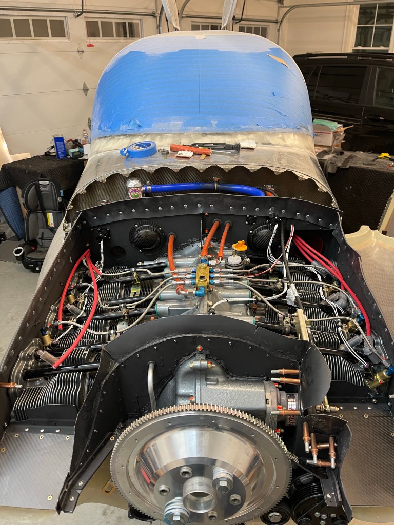
The next couple of pics are from the front.
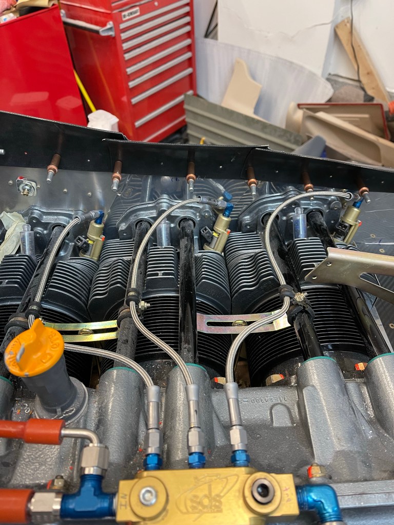
The right side of the engine.
Boy does it really get busy in the space between the firewall and the engine. Especially when you have 2 coil packs for the spark plugs.
The left side of the engine.
Again busy busy.. It really took so much time not only to wire things, but to come up with reasonable routes and securing things.
Now its back to finishing the inside wiring and getting my panel powered up!
Most of the FWF fuel and oil hoses are complete now minus some Adel clamps that still need to be added. I’ve tried to annotate the pictures as much as possible to help show what all the hoses are.
Below you can see the main fuel supply comes out of the firewall bulkhead fitting on the left (pilots) side and attaches to the SDS post filter. In this picture is also one of the two oil cooler lines that connects to the engine.
Below is the closeup of the post filter clamped to the engine mount.
The fuel supply comes out of the post filter and continues on to the fuel rail after it passes through the baffling. Also shown is the fuel pressure line that comes back to a sensor, the other oil cooler line, and the oil pressure line.
A better view of both lines coming out of the oil cooler.
The blue hose is the oil breather line connected to the Air/Oil separator. This configuration will keep oil off the belly of the airplane. I also added an adel clamp on the firewall to hold it midway.
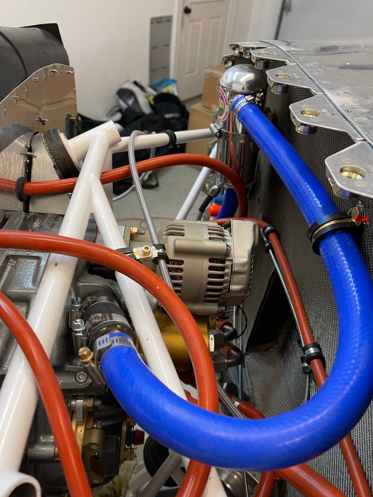
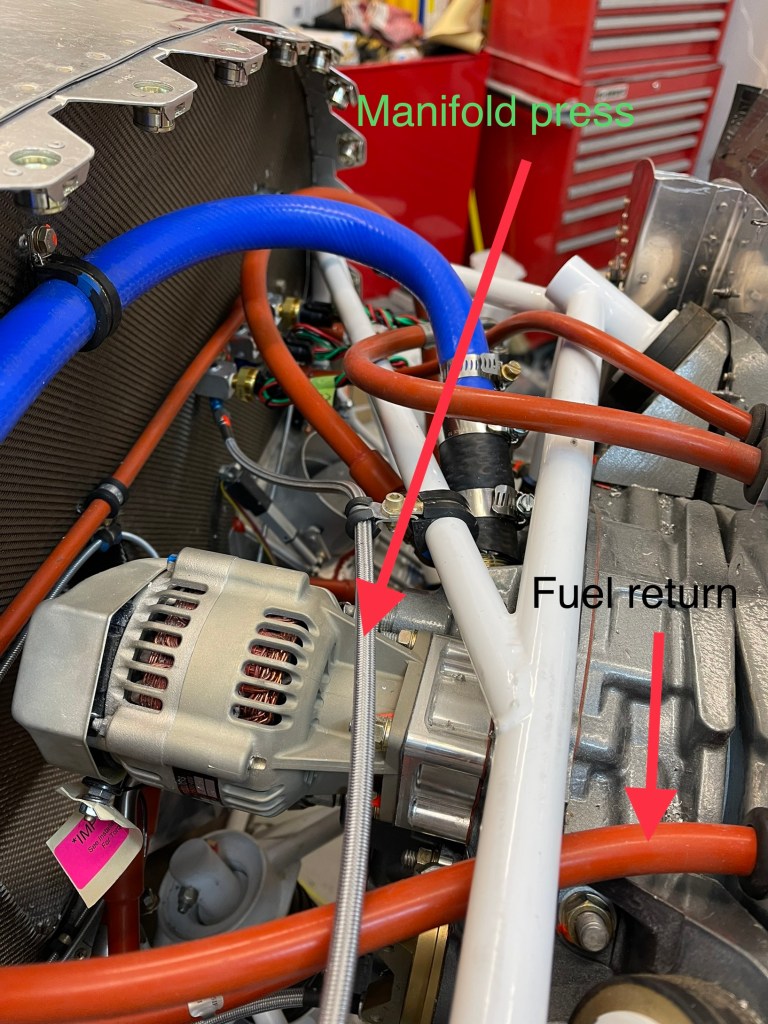
Moving to the other side of the engine, we have the manifold pressure line coming from the sensor on the manifold block. You can also see here the fuel return line coming through the baffling as it makes its way back to the fuel pressure regulator.
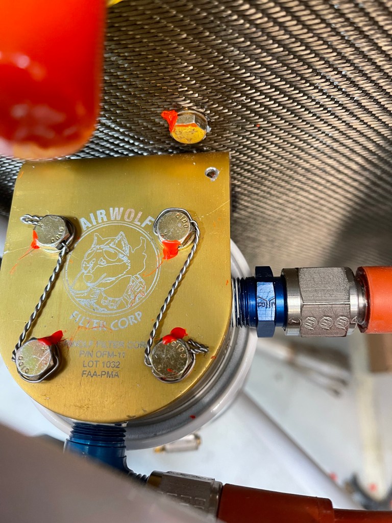
One of the add-ons I decided on was a remote oil filter adapter. This will make oil changes much easier with the filter readily accessible and with the filter oriented vertical, all excess oil will be in the filter when you spin it off preventing a mess. This does, however, require 2 additional hoses to get back and forth to the engine as shown here.
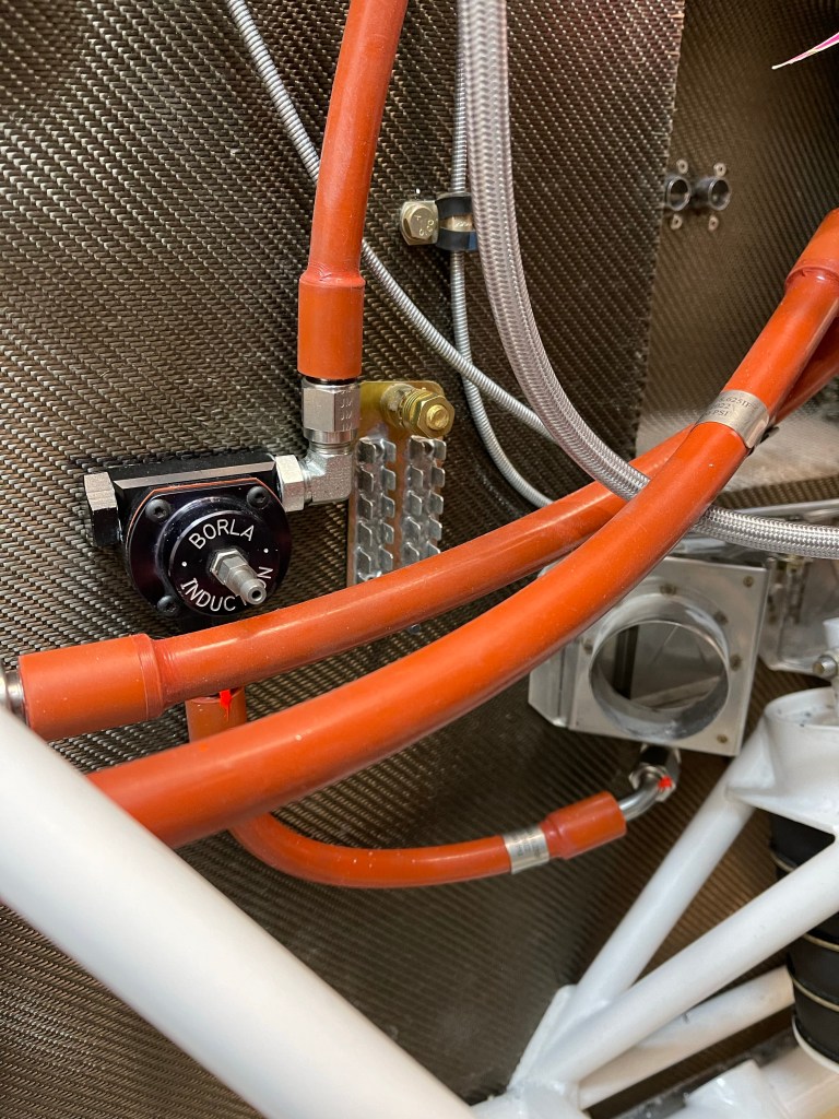
Below you see the Borla pressure regulator for the SDS system mounted to the firewall and taking return fuel (top right) from the engine, and returning it to the firewall mounted bulkhead fitting below the heat box on the right (copilots) side. I still need to attach a manifold line to the center of the regulator.
Looking at the engine side and the fuel block on top of the case.. you can see the supply, return, and pressure lines as they make their way from the rear baffle to the block. There is a T fitting in the supply inlet to provide the pressure back to the sensor.
Each of the cylinder is fed out of the sides of the fuel block like the 3 cylinders shown below.
I also drilled a small hole in the oil filter adapter to attach safety wire to when safetying the oil filter itself.. not done here as the install is all temporary for now.
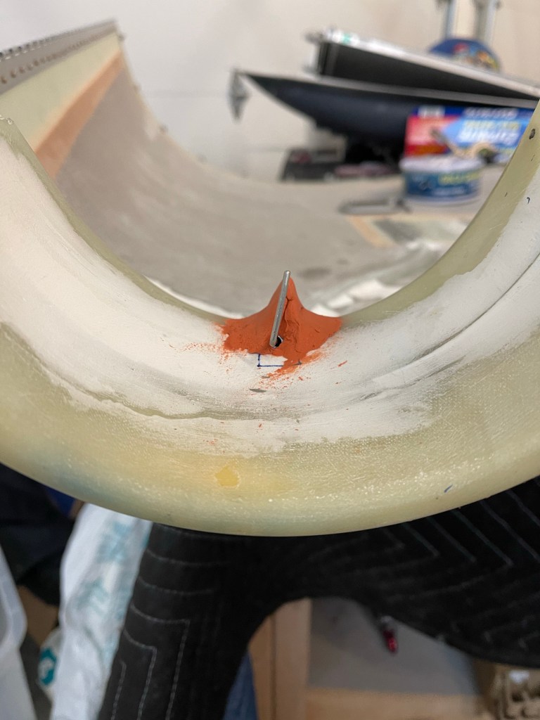
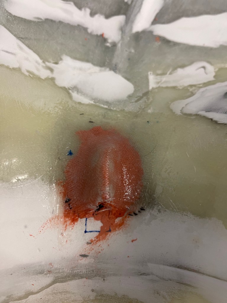
One of the other things I needed to finish up as creating an airfoil of sorts to back up the pin for the hidden oil door. I used some air-drying modeling clay to form the shape that I wanted.
I then laid up a few layers of fiberglass cloth over the clay and allowed it to cure overnight.
I finished it off with some micro and sanded it smooth.
With the pin inserted.
Another task I needed to figure out was how to feed air into the left side heat muff. With the AC compressor installed on the engine there is no good way to use anything from the air inlet area like the stock setup does. The only options I saw were to feed it from the aft baffle (like the right side does), feed it from the left intake snorkel, pull from the right inlet area (but this is also tight with the alternator over there), or add NACA vents to the lower cowl.
I’ve decided on pulling from the left intake snorkel. This does steal some combustion air , but the Showplane’s setup is designed to only need air from one side to be sufficient. So I will add a 2″ SCAT tube between the locations shown with arrows below. Of course, I’m going to need to get a 180* setup for the #2 cylinder heat muff from Custom Aircraft parts instead of the normal 62.5* one I have now. This will have air come in from the outside of the exhaust and intake tubes to the engine and the outlet will be on the inside of those tubes feeding the left heat box.
A rough mock-up of where the 2″ SCAT tube will go. There seems to be sufficient space between the lower cowl and the engine to do this.
A rough approximation of where the inlet to the heat muff will be.
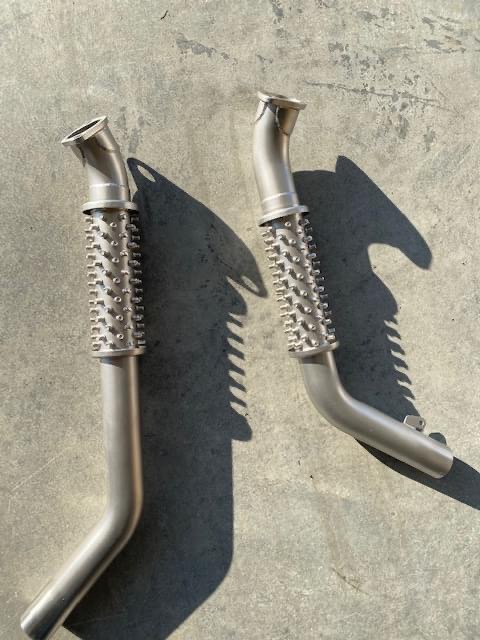
In talking to Clinton about this, he’s also been fighting some cracking in the exhaust on the left side. He had previously sent me a support setup for the exhaust to help with vibration, which I have, but haven’t done anything with it quite yet. He asked that I install my exhaust and check for any interference with the intake tubes and in the end, I’ll need to send my entire left side of the exhaust back to him for modification to help prevent cracking in the future.
Left side of exhaust installed. Right side installed.
While sending it back, I’m also going to have him “stud” the heat muffs on both sides (as shown below) to allow for some better heat transfer. I didn’t know about this option prior to ordering and it apparently helps get some more heat for the colder months. The stock Vetterman exhaust is known to have too much heat, but that’s not always the case with the Custom system.
Picture of Bob Lusslow’s studded exhaust that I’m going to have done.
Back when I installed my fuel lines, Tom from AS Flightlines ( http://www.aircraftspecialty.com) really only had one solution to the SDS fuel filters. On top of the fuel pump module using adel clamps. I really don’t like having these in the tunnel for maintenance reasons. It seems inevitable that some amount of fuel will spill out into the tunnel no matter how careful I am trying to catch it all as I take this all apart for yearly service. Additionally, I placed the access panels on the tunnel sidewalls a little further aft and not perfectly aligned to the whole assembly, so access to the forward-most fittings is a bit challenging. Taking the top of the tunnel off, while doable, is a royal pain seeing there are throttle cables, etc.. routed on top of that. I really have always viewed this solution as something I’m going to regret and will spend way more time than I really should on each condition inspection. Also I can envision lots of curse words being used. Below is a view of the original filter setup in the tunnel.
Original tunnel fuel filter arrangement.
Since that time, Tom has come up with pre-filters in the wing roots, and moving the post filter firewall forward. Despite having some re-do.. I opted to take some time now to change and use this new configuration. Maintenance will be much easier and more accessible that way. If fuel does spill, it’ll be outside of the cabin. With just the fuel pump in the tunnel, there will be basically no reason to ever go in there very often at all, other than to remove the access panels and check on the pumps.
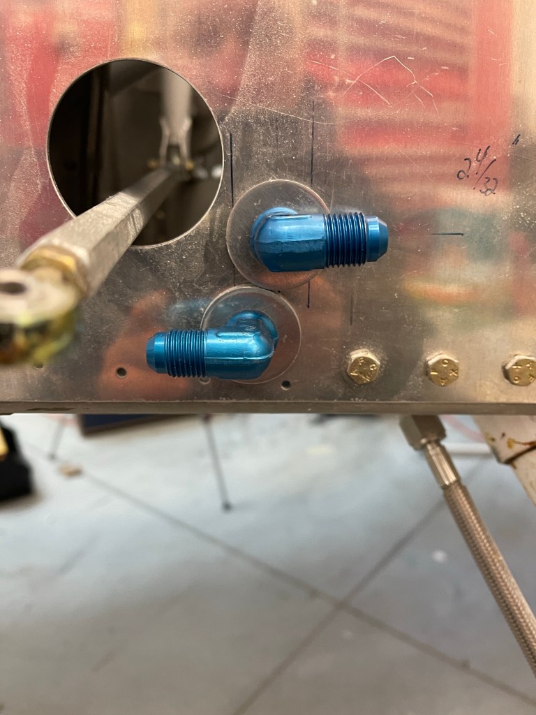
Of course that meant all new cabin hoses and some additional expense, but Tom actually helped out in this regard. I also went with some other arrangements that Tom has standardized on for routing, like having the supply come out on the left side of the firewall and return on the right. One thing that we did decide on was seeing we had to remake the hoses under my seats, was to re-use the hole I had already cut for one of the fuel lines. I cut this hole pretty close to the stock supply hose location and sided it just big enough to get a -6 hose swivel fitting through. Seeing both the stock and hole I drilled were too big for normal AN bulkhead fittings, I had to utilize the TCW fittings (https://www.tcwtech.com). Bob has come up with a washer with a neck/bushing on the inside that fits into the 1″ stock location so the fitting doesn’t fall through the hole. I also asked Bob if he could make me a custom one for the 25/32″ hole that I had already drilled. He made it the next day and had it off to me. I’d say I had a bit of shit luck with how these 2 washers fit basically perfectly. I really figured I was going to have to carve a half moon in one of them for clearance to the other.
Supply and return fittings on the fuselage side skin.
I installed 2 new hoses under each seat for the supply and return.
Below you can see the routing to the side skins. In retrospect, I really wish I didn’t route my brake line in the middle row of the systems brackets.. It would minimize hose crossovers.. In the end the right-most hose in the picture below passes under the brake hose with some clearance. The left-most hose is angled enough with the 45* fitting that it also clears everything.
Routing of hose lines to side skin.
I then spent some time re-locating the pump module. I used the “standard” length hoses from Tom to place this. I also noticed that I needed to raise the module up 2″ from the 3/4″x3/4″ angle I had placed on the tunnel sidewalls already.
Using the hose lengths to place the pump module.
In order to raise the module up, I decided on using some square aluminum tubing. I could some 2″x2″x.125″ material on Aircraft Spruce and ended up cutting 2 pieces. I re-used one set of holes and nut plates I already had on the angle for the aft-most tube. I then added 2 new pieces of angle for the forward tube as shown below.
Using square tubing to elevate the pump module 2″
I was then able to bolt the pump module down with 4 bolts into the square tubing with nut plates and AN3 bolts. I added a couple of adel clamps to the longer return hose as it made its way back to the selector valve.
Finalized pump module
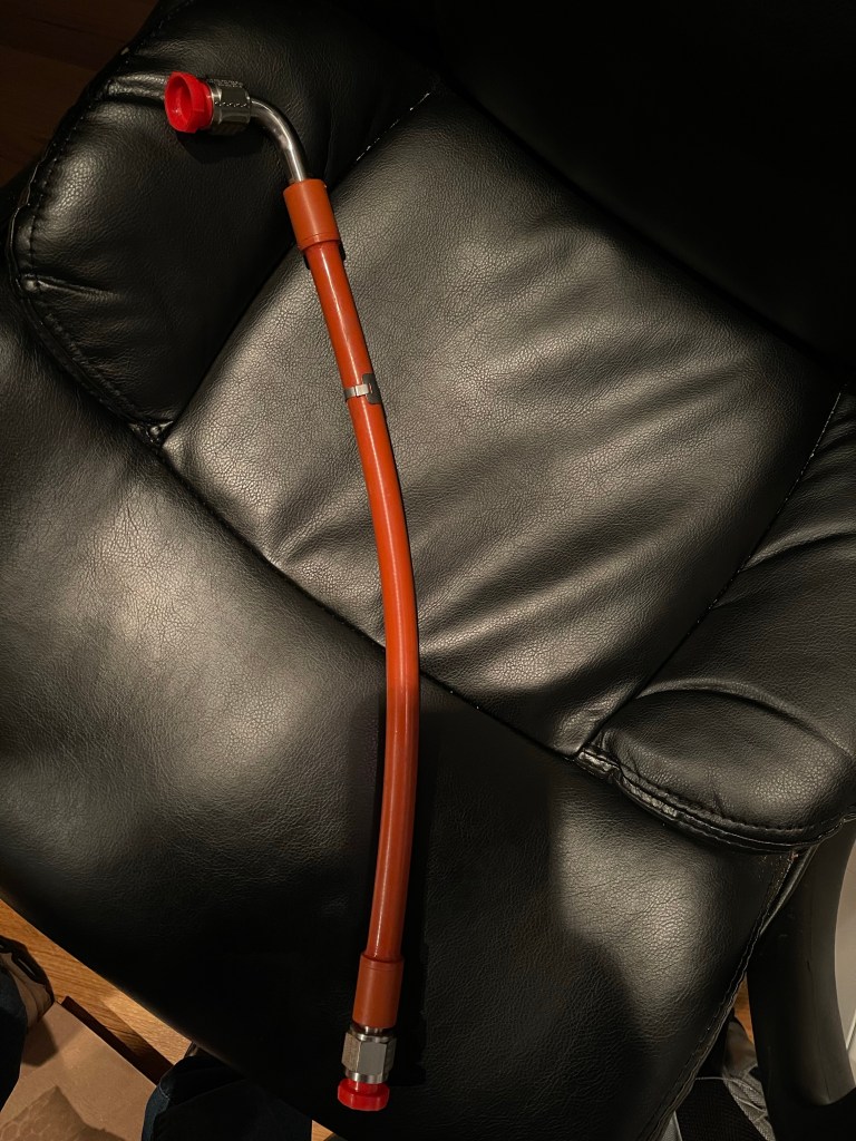
Tom also sent along my FWF package with integral firesleeved hoses.
Example of the integral fire sleeve hose
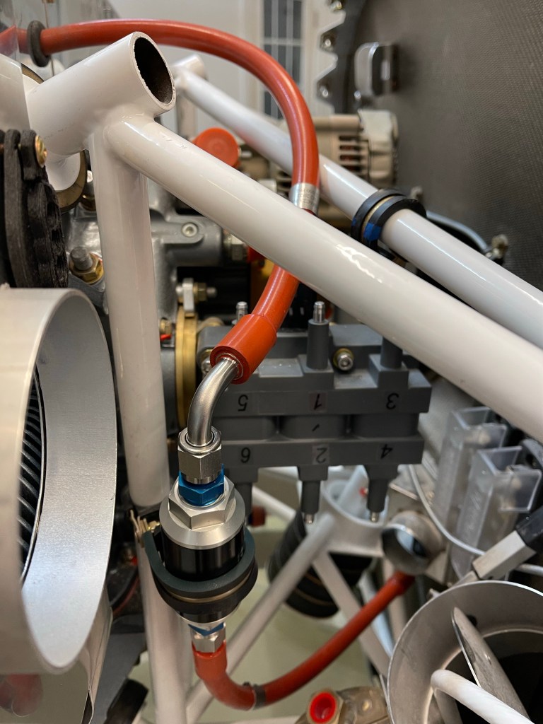
I started on the fuel supply and routing it from the firewall to the post-filter to the fuel block on the top of the engine. This hose passes through the aft baffle with a grommet.
FW to post filter hose. Post filter location on engine mount vertical tube and routing through baffle Supply hose to fuel supply rail on engine top. The T fitting is for fuel pressure back to the manifold block on the firewall.
More FWF plumbing to come now that the cabin and pump are complete.