
Back when I installed my fuel lines, Tom from AS Flightlines ( http://www.aircraftspecialty.com) really only had one solution to the SDS fuel filters. On top of the fuel pump module using adel clamps. I really don’t like having these in the tunnel for maintenance reasons. It seems inevitable that some amount of fuel will spill out into the tunnel no matter how careful I am trying to catch it all as I take this all apart for yearly service. Additionally, I placed the access panels on the tunnel sidewalls a little further aft and not perfectly aligned to the whole assembly, so access to the forward-most fittings is a bit challenging. Taking the top of the tunnel off, while doable, is a royal pain seeing there are throttle cables, etc.. routed on top of that. I really have always viewed this solution as something I’m going to regret and will spend way more time than I really should on each condition inspection. Also I can envision lots of curse words being used. Below is a view of the original filter setup in the tunnel.

Since that time, Tom has come up with pre-filters in the wing roots, and moving the post filter firewall forward. Despite having some re-do.. I opted to take some time now to change and use this new configuration. Maintenance will be much easier and more accessible that way. If fuel does spill, it’ll be outside of the cabin. With just the fuel pump in the tunnel, there will be basically no reason to ever go in there very often at all, other than to remove the access panels and check on the pumps.
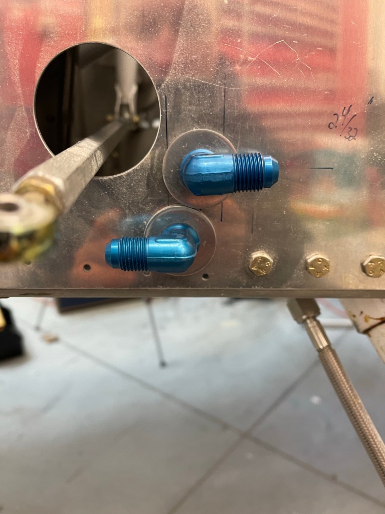
Of course that meant all new cabin hoses and some additional expense, but Tom actually helped out in this regard. I also went with some other arrangements that Tom has standardized on for routing, like having the supply come out on the left side of the firewall and return on the right. One thing that we did decide on was seeing we had to remake the hoses under my seats, was to re-use the hole I had already cut for one of the fuel lines. I cut this hole pretty close to the stock supply hose location and sided it just big enough to get a -6 hose swivel fitting through. Seeing both the stock and hole I drilled were too big for normal AN bulkhead fittings, I had to utilize the TCW fittings (https://www.tcwtech.com). Bob has come up with a washer with a neck/bushing on the inside that fits into the 1″ stock location so the fitting doesn’t fall through the hole. I also asked Bob if he could make me a custom one for the 25/32″ hole that I had already drilled. He made it the next day and had it off to me. I’d say I had a bit of shit luck with how these 2 washers fit basically perfectly. I really figured I was going to have to carve a half moon in one of them for clearance to the other.
I installed 2 new hoses under each seat for the supply and return.

Below you can see the routing to the side skins. In retrospect, I really wish I didn’t route my brake line in the middle row of the systems brackets.. It would minimize hose crossovers.. In the end the right-most hose in the picture below passes under the brake hose with some clearance. The left-most hose is angled enough with the 45* fitting that it also clears everything.

I then spent some time re-locating the pump module. I used the “standard” length hoses from Tom to place this. I also noticed that I needed to raise the module up 2″ from the 3/4″x3/4″ angle I had placed on the tunnel sidewalls already.

In order to raise the module up, I decided on using some square aluminum tubing. I could some 2″x2″x.125″ material on Aircraft Spruce and ended up cutting 2 pieces. I re-used one set of holes and nut plates I already had on the angle for the aft-most tube. I then added 2 new pieces of angle for the forward tube as shown below.

I was then able to bolt the pump module down with 4 bolts into the square tubing with nut plates and AN3 bolts. I added a couple of adel clamps to the longer return hose as it made its way back to the selector valve.

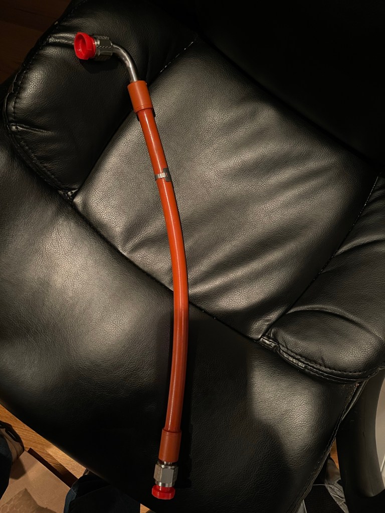
Tom also sent along my FWF package with integral firesleeved hoses.
I started on the fuel supply and routing it from the firewall to the post-filter to the fuel block on the top of the engine. This hose passes through the aft baffle with a grommet.

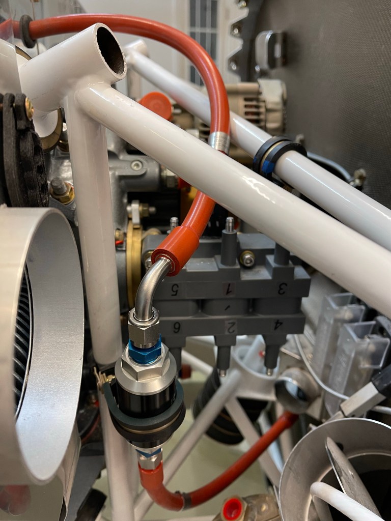

More FWF plumbing to come now that the cabin and pump are complete.
