FWF hoses, Oil door pin airfoil, and exhaust update

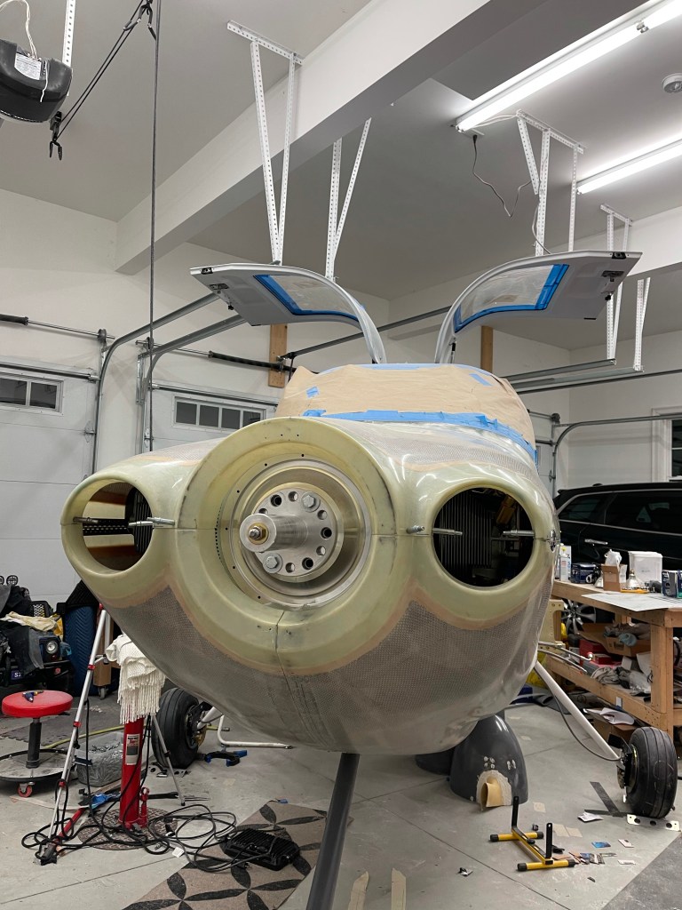
Most of the FWF fuel and oil hoses are complete now minus some Adel clamps that still need to be added. I’ve tried to annotate the pictures as much as possible to help show what all the hoses are.

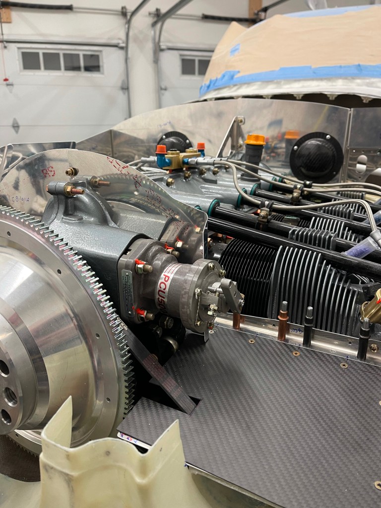
Below you can see the main fuel supply comes out of the firewall bulkhead fitting on the left (pilots) side and attaches to the SDS post filter. In this picture is also one of the two oil cooler lines that connects to the engine.

Below is the closeup of the post filter clamped to the engine mount.

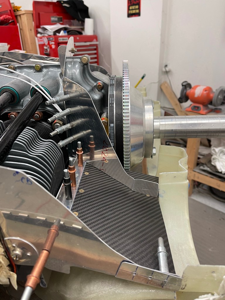
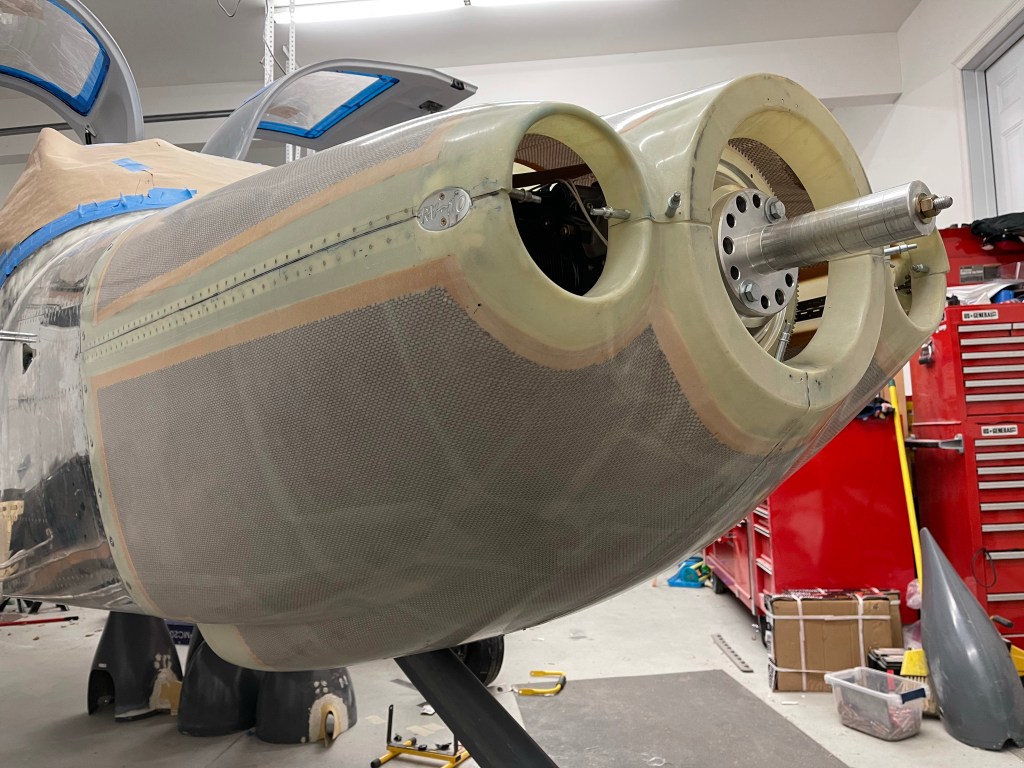
The fuel supply comes out of the post filter and continues on to the fuel rail after it passes through the baffling. Also shown is the fuel pressure line that comes back to a sensor, the other oil cooler line, and the oil pressure line.

A better view of both lines coming out of the oil cooler.

The blue hose is the oil breather line connected to the Air/Oil separator. This configuration will keep oil off the belly of the airplane. I also added an adel clamp on the firewall to hold it midway.

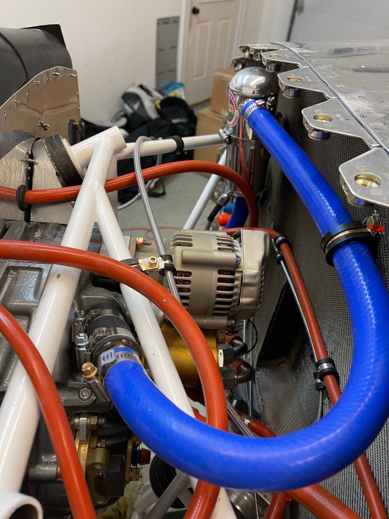
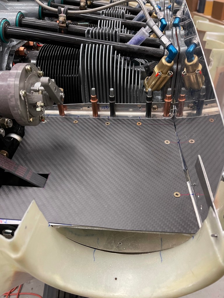
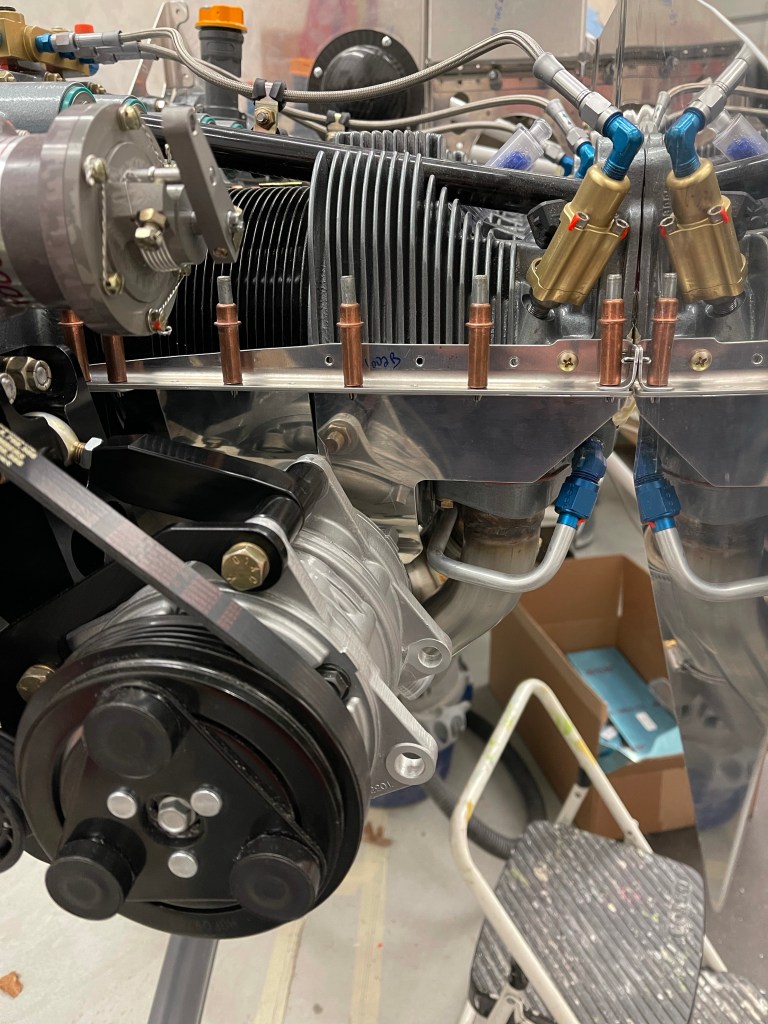
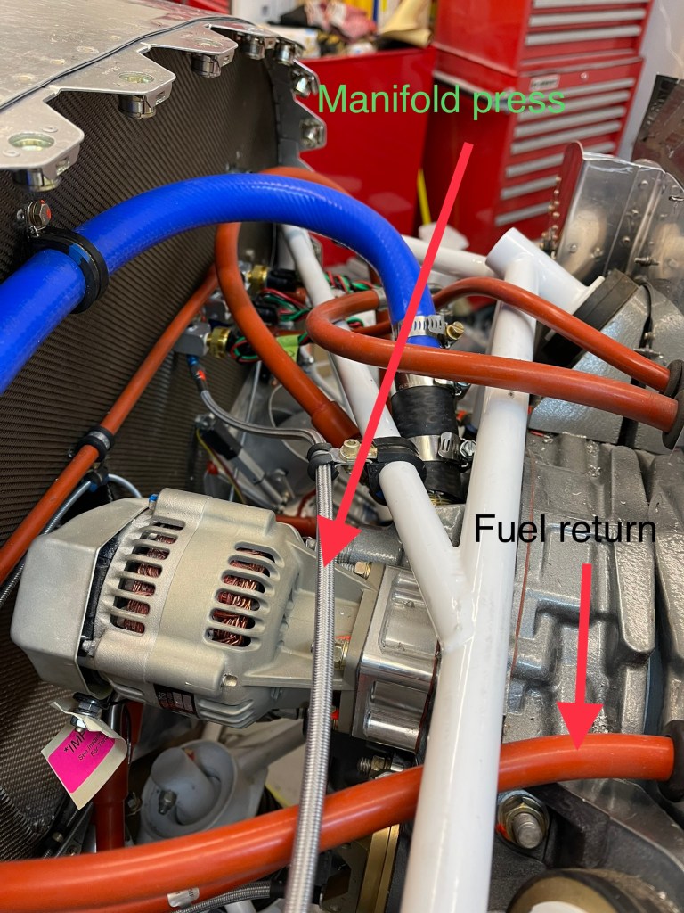
Moving to the other side of the engine, we have the manifold pressure line coming from the sensor on the manifold block. You can also see here the fuel return line coming through the baffling as it makes its way back to the fuel pressure regulator.

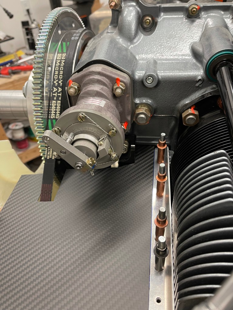
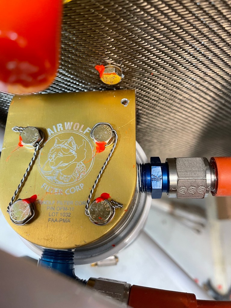
One of the add-ons I decided on was a remote oil filter adapter. This will make oil changes much easier with the filter readily accessible and with the filter oriented vertical, all excess oil will be in the filter when you spin it off preventing a mess. This does, however, require 2 additional hoses to get back and forth to the engine as shown here.

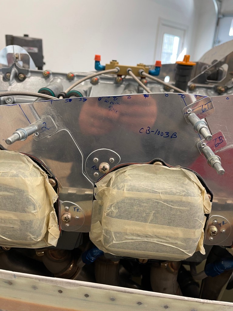
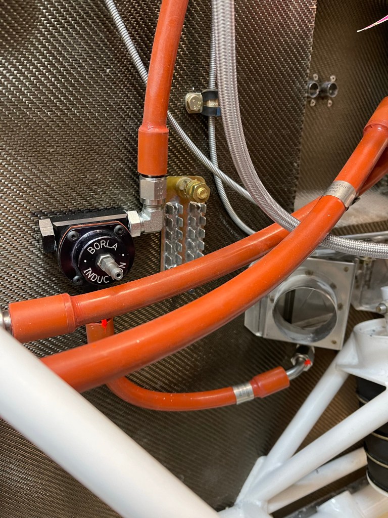
Below you see the Borla pressure regulator for the SDS system mounted to the firewall and taking return fuel (top right) from the engine, and returning it to the firewall mounted bulkhead fitting below the heat box on the right (copilots) side. I still need to attach a manifold line to the center of the regulator.

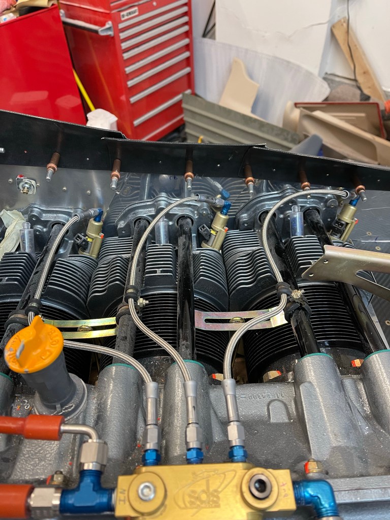
Looking at the engine side and the fuel block on top of the case.. you can see the supply, return, and pressure lines as they make their way from the rear baffle to the block. There is a T fitting in the supply inlet to provide the pressure back to the sensor.

Each of the cylinder is fed out of the sides of the fuel block like the 3 cylinders shown below.

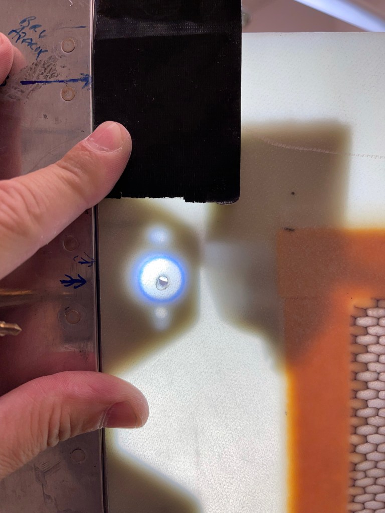
I also drilled a small hole in the oil filter adapter to attach safety wire to when safetying the oil filter itself.. not done here as the install is all temporary for now.

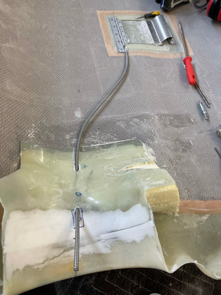
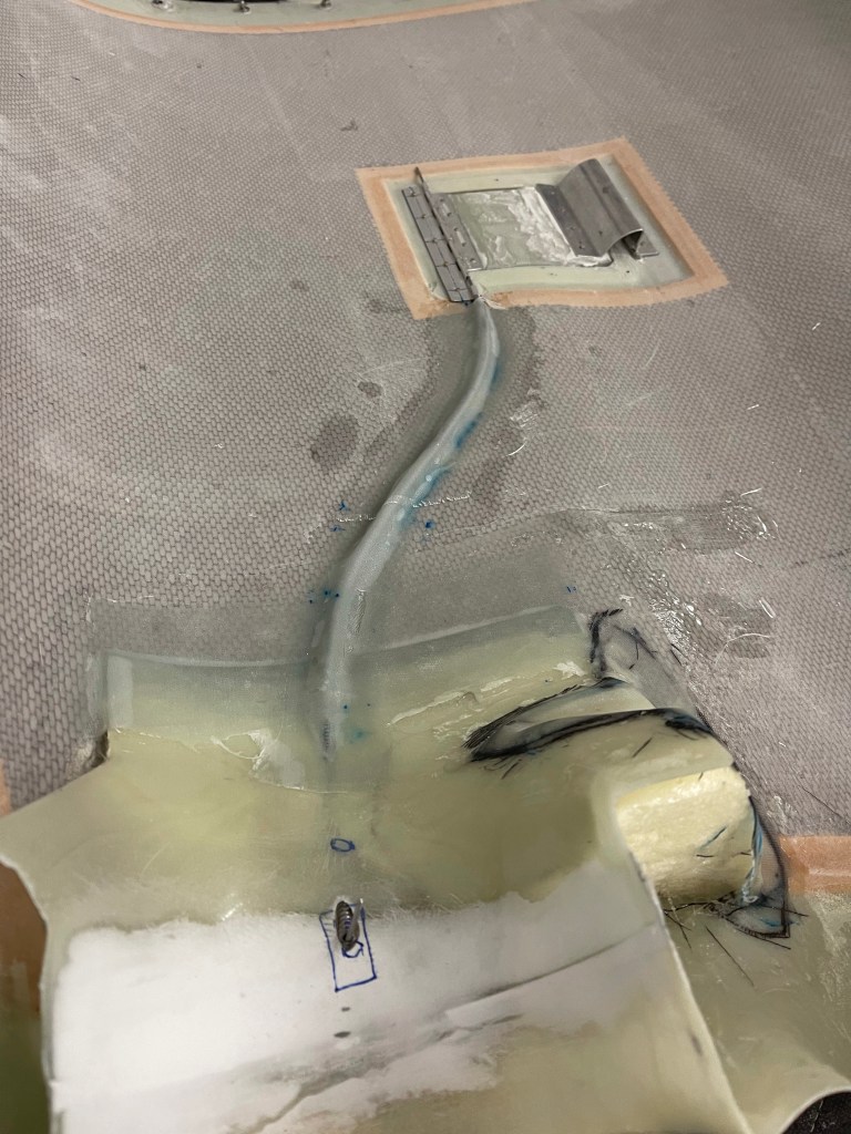
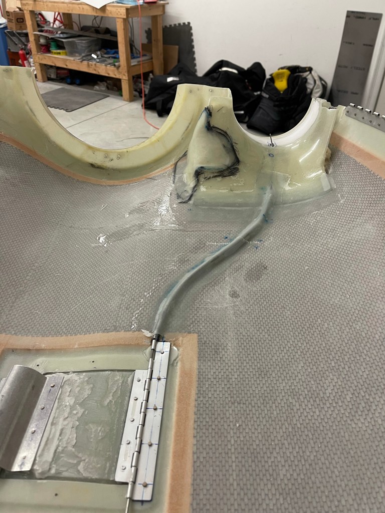
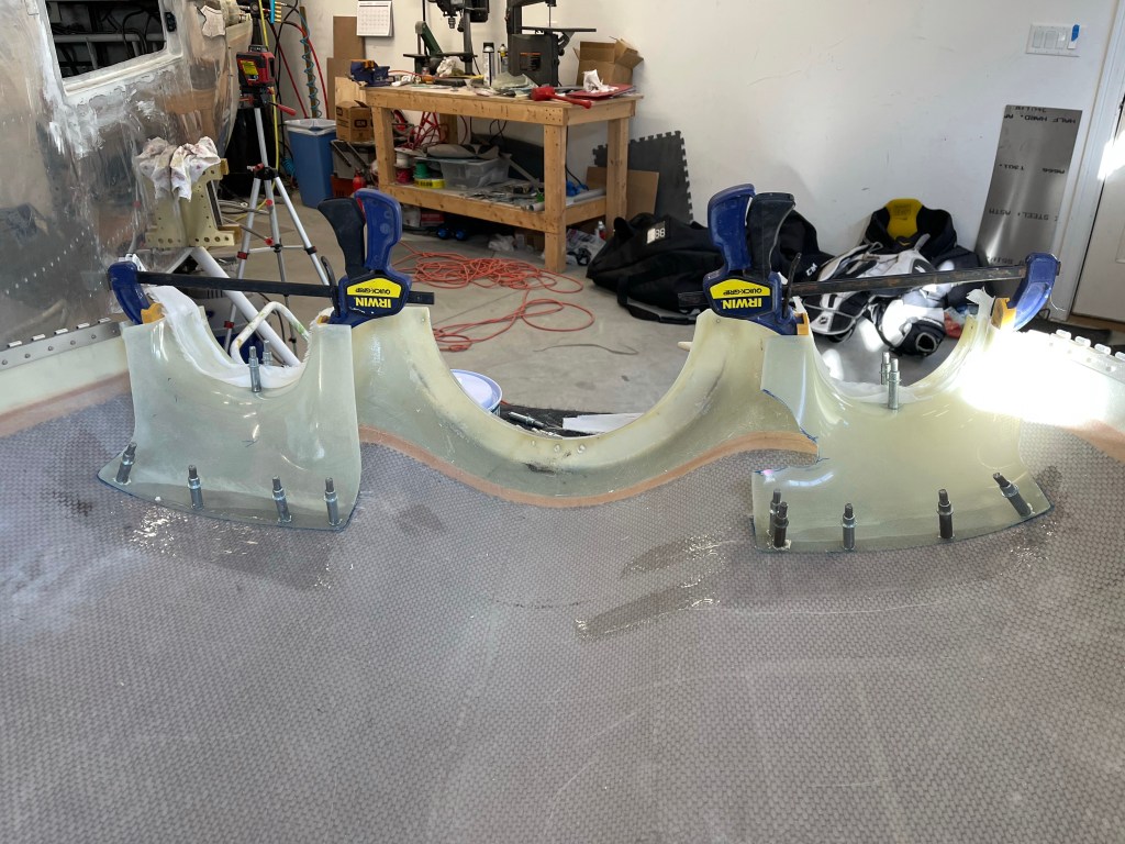
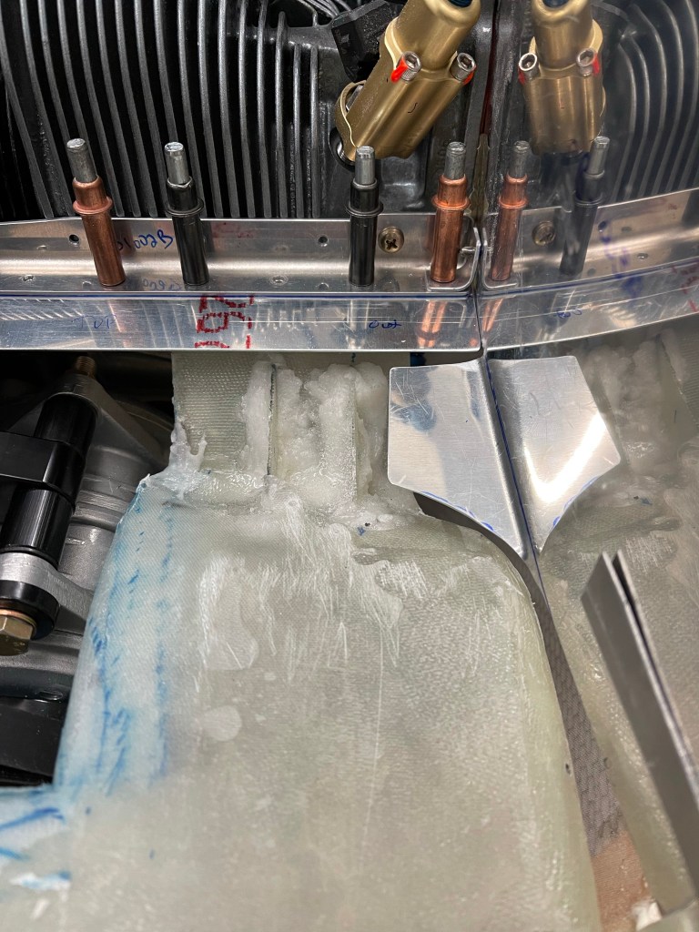
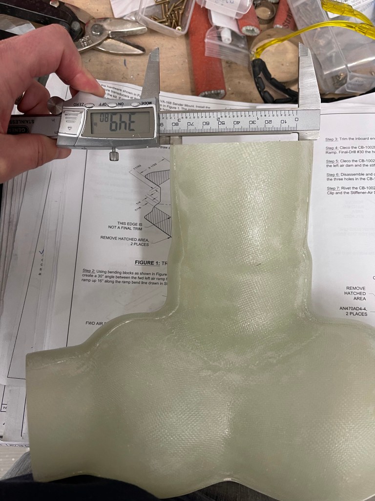
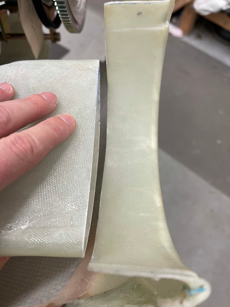
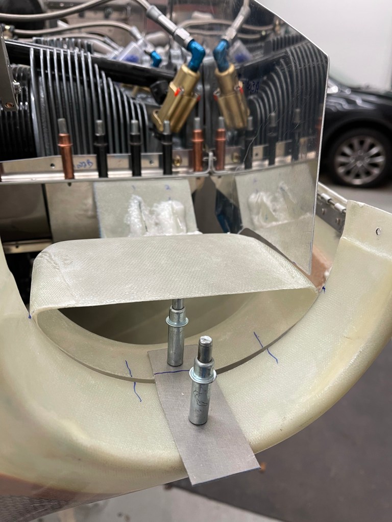
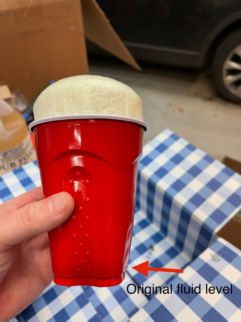
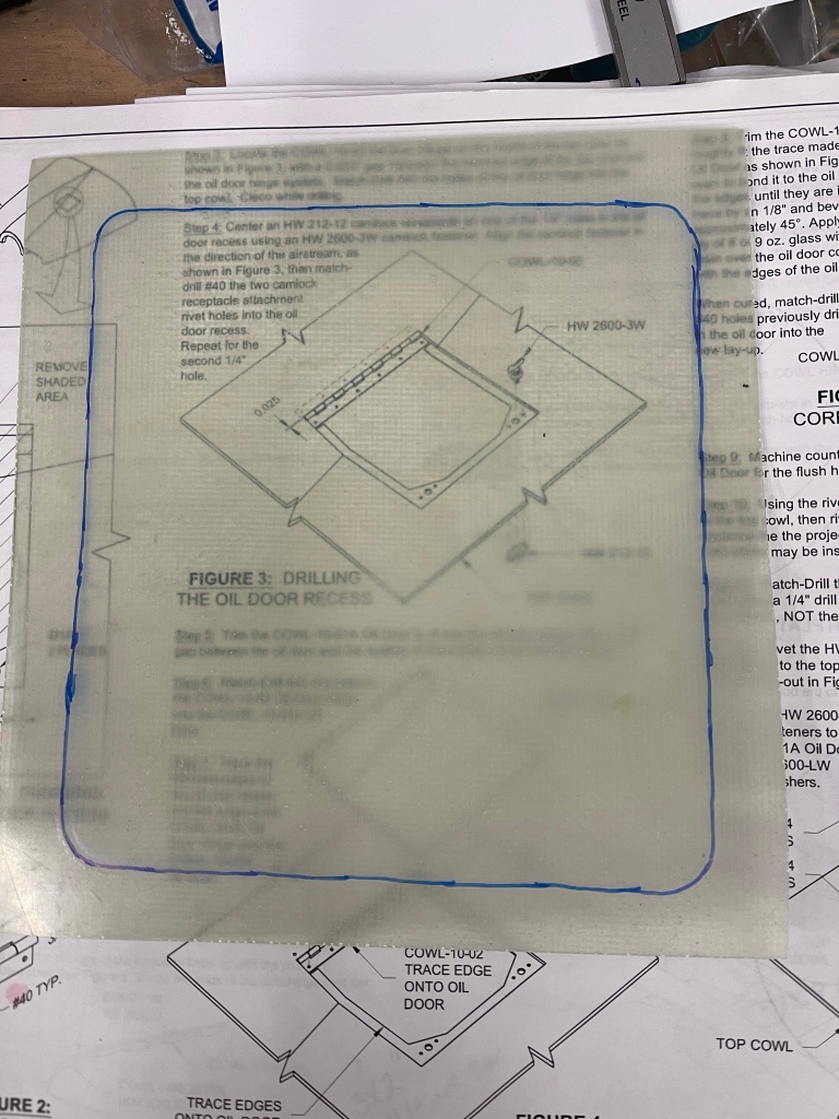
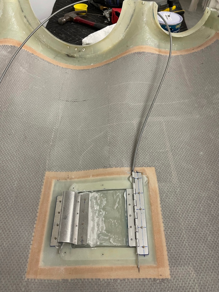
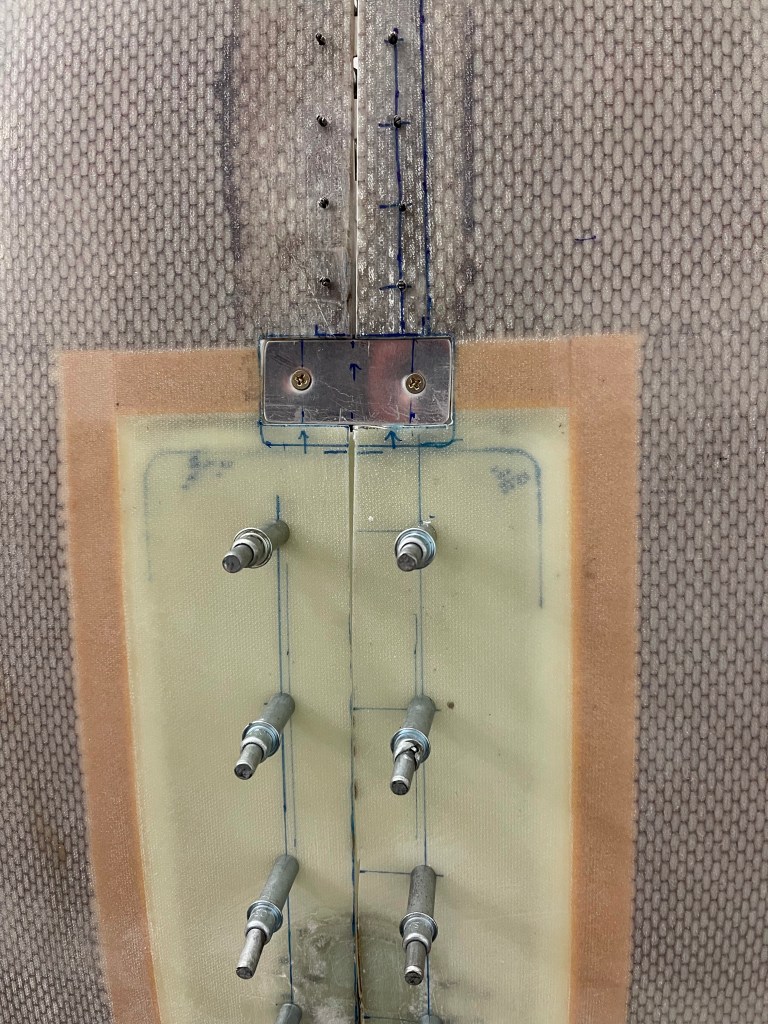
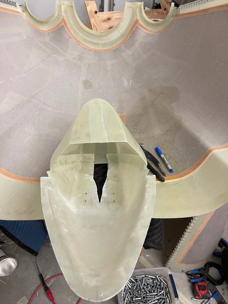
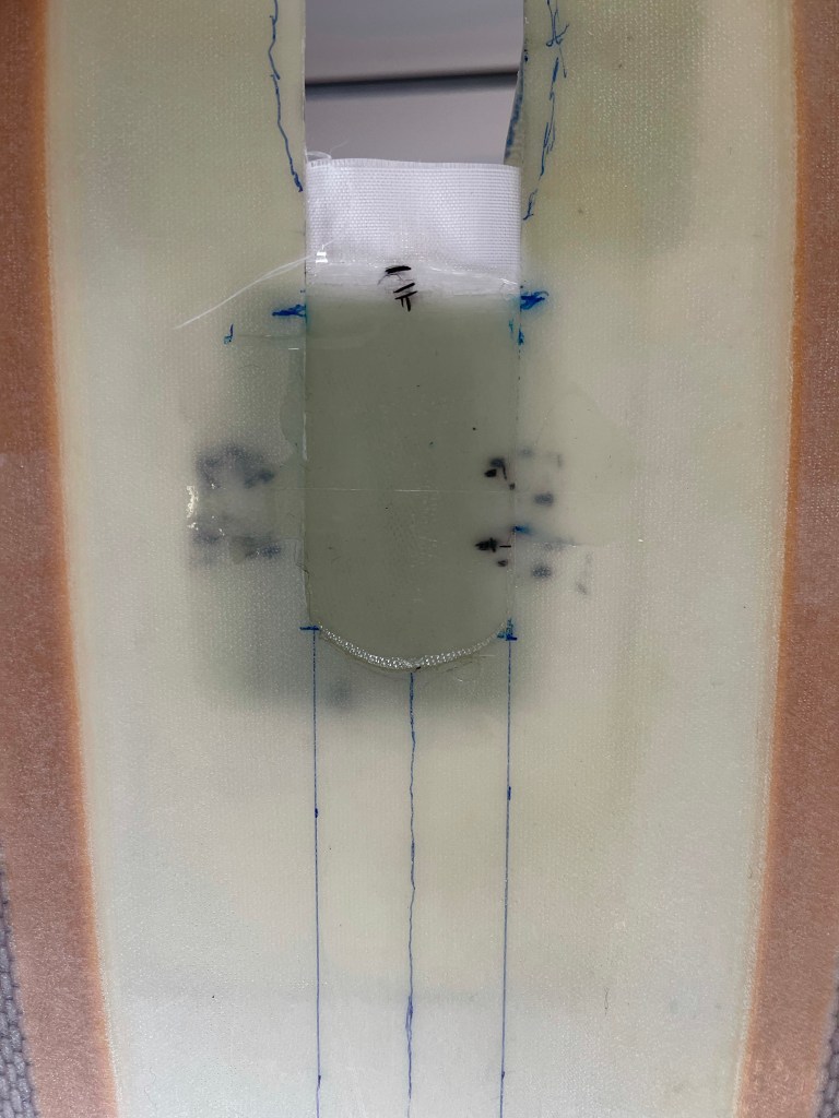
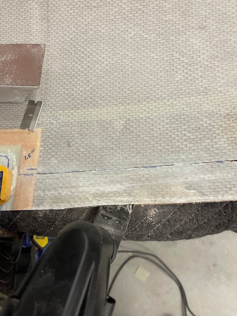
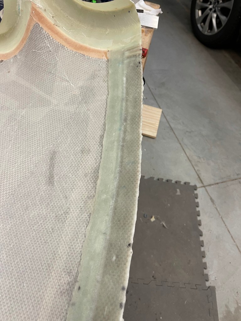
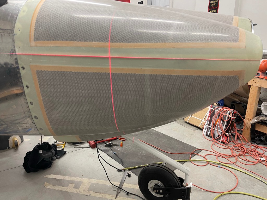
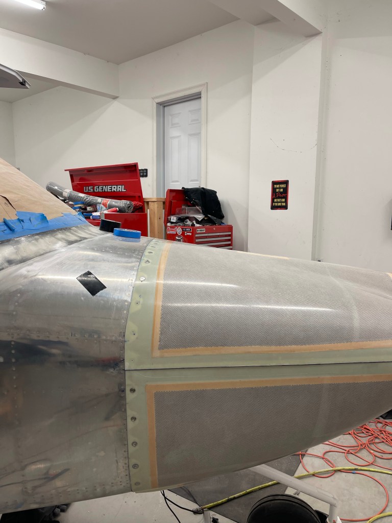
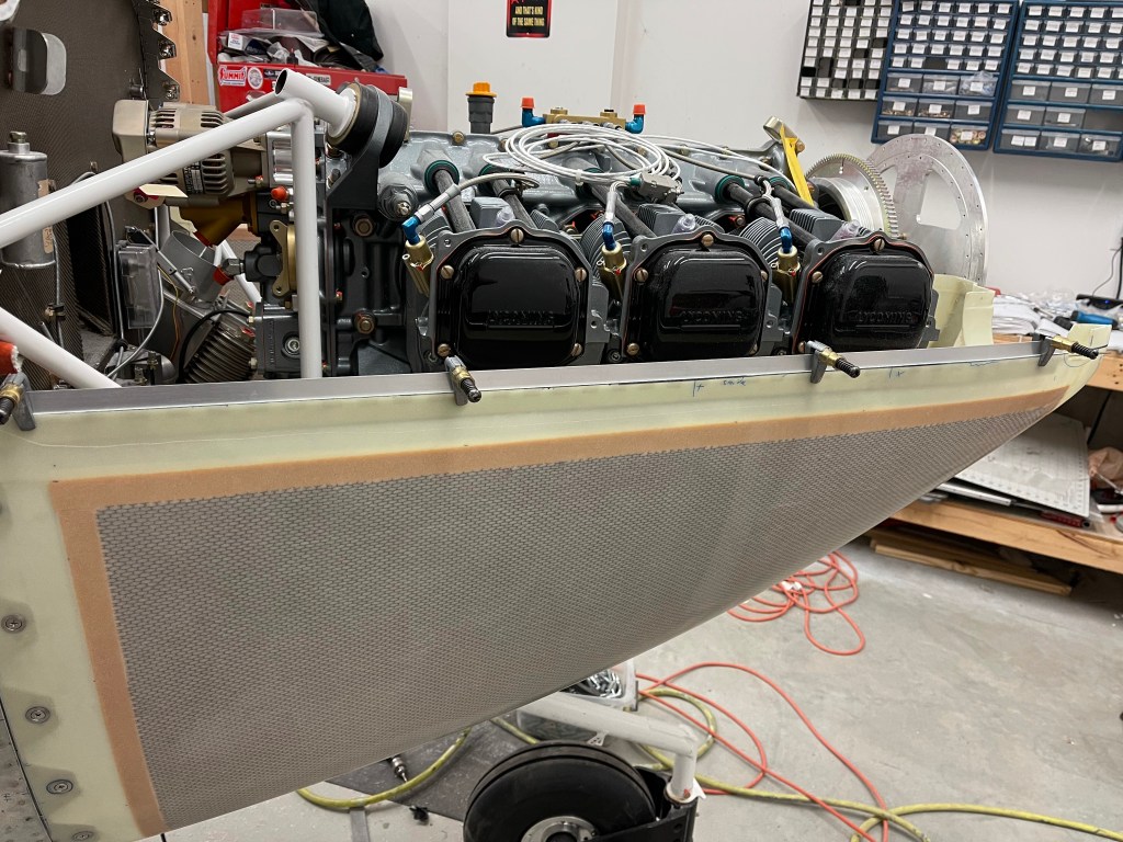
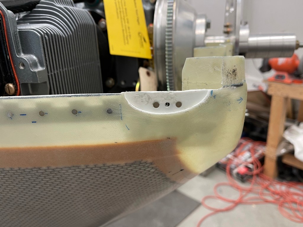
One of the other things I needed to finish up as creating an airfoil of sorts to back up the pin for the hidden oil door. I used some air-drying modeling clay to form the shape that I wanted.

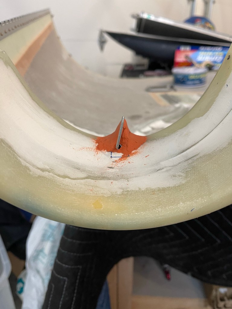
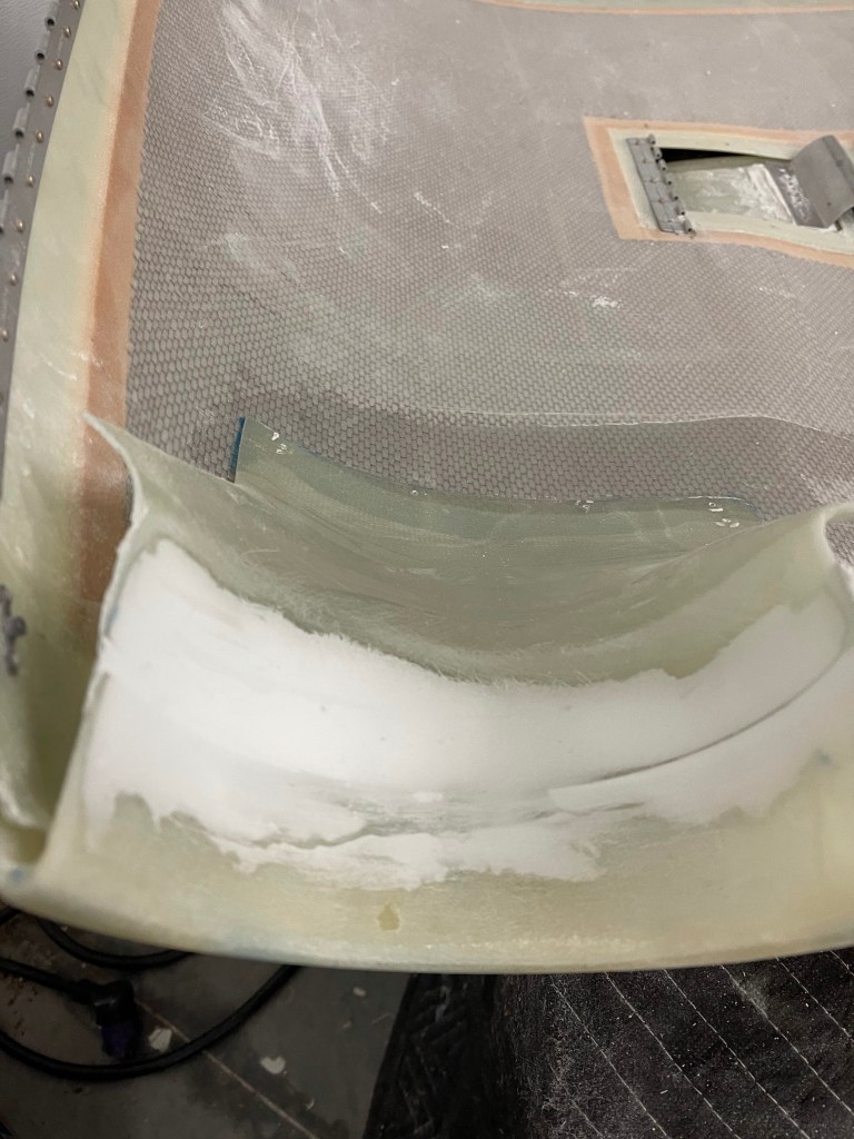
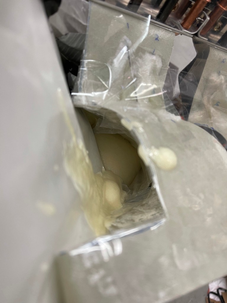
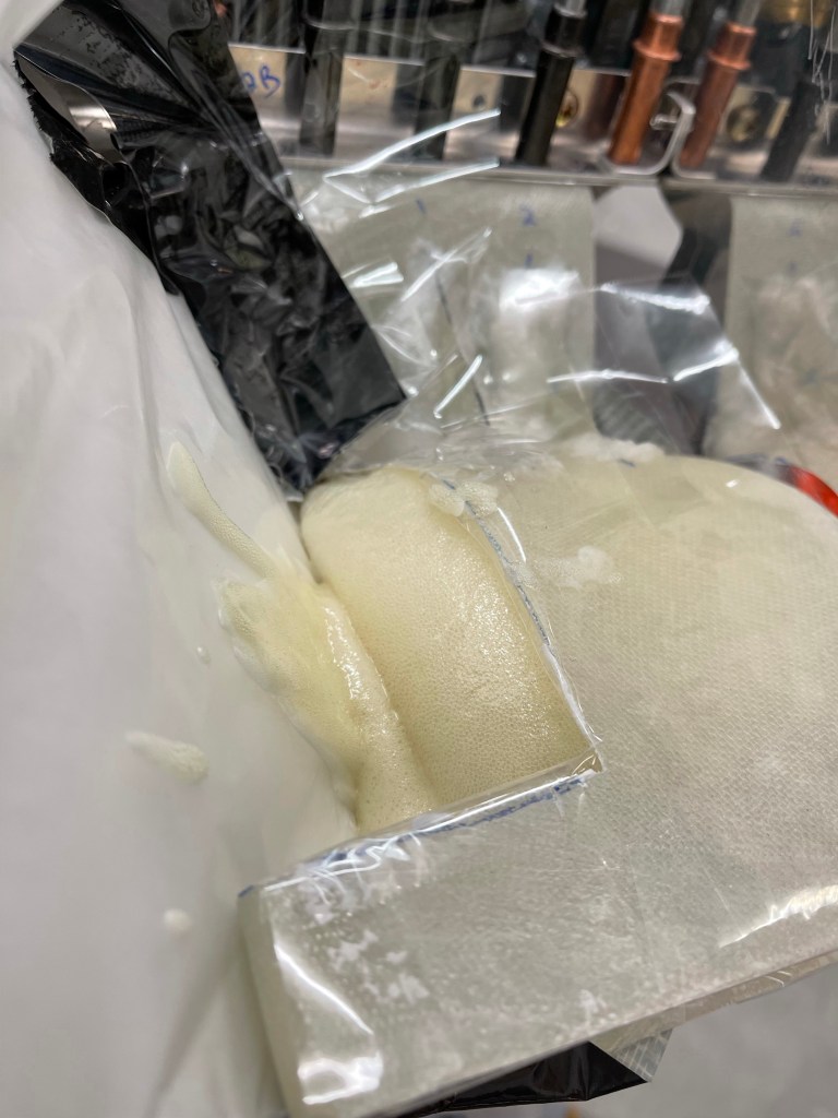
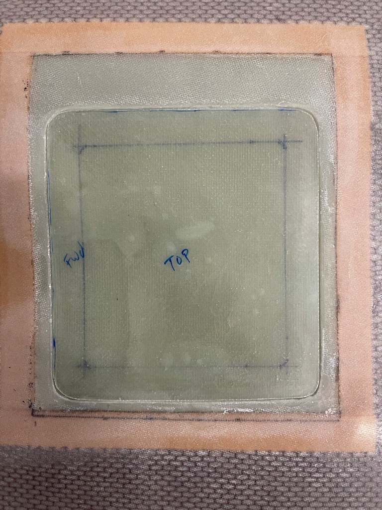
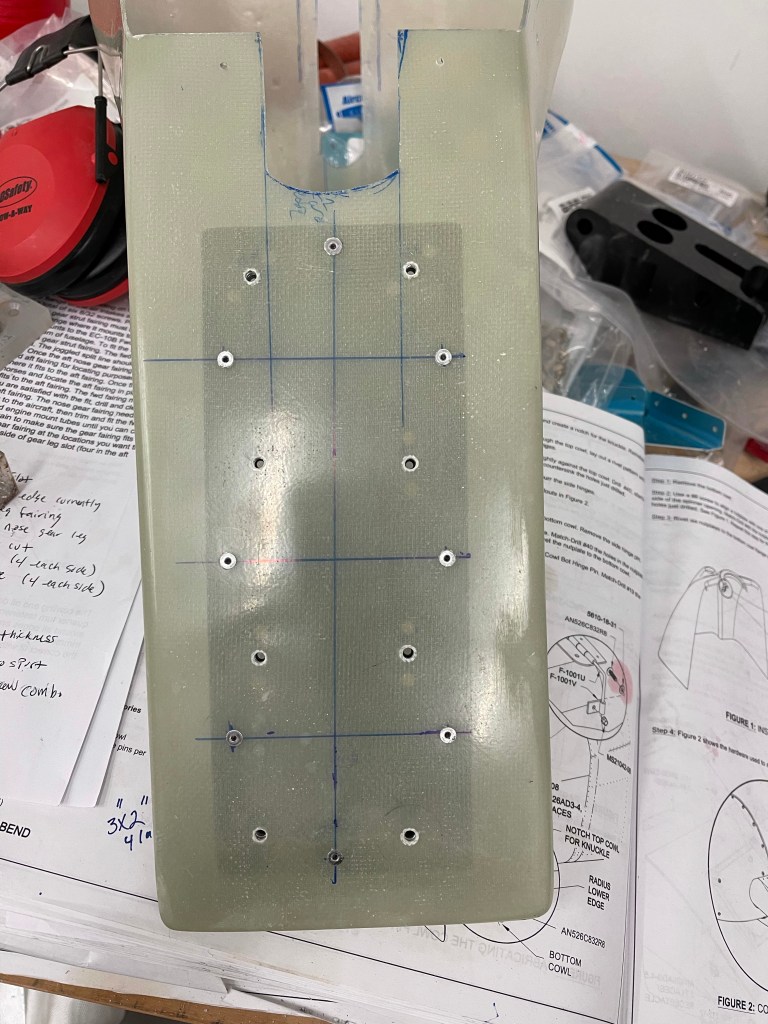
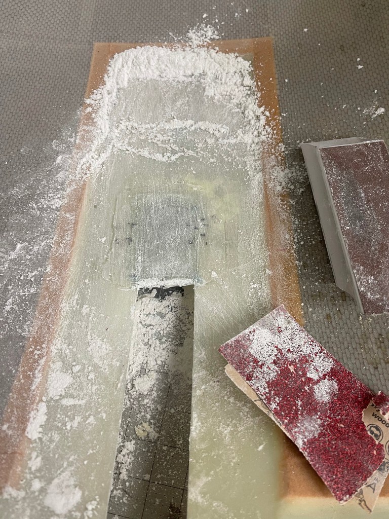
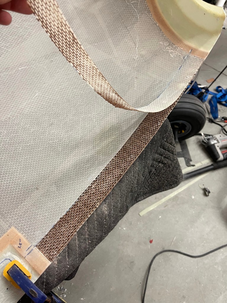
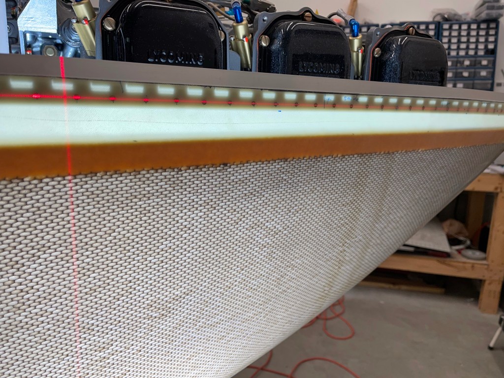
I then laid up a few layers of fiberglass cloth over the clay and allowed it to cure overnight.

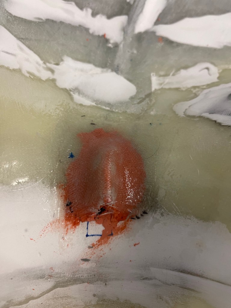
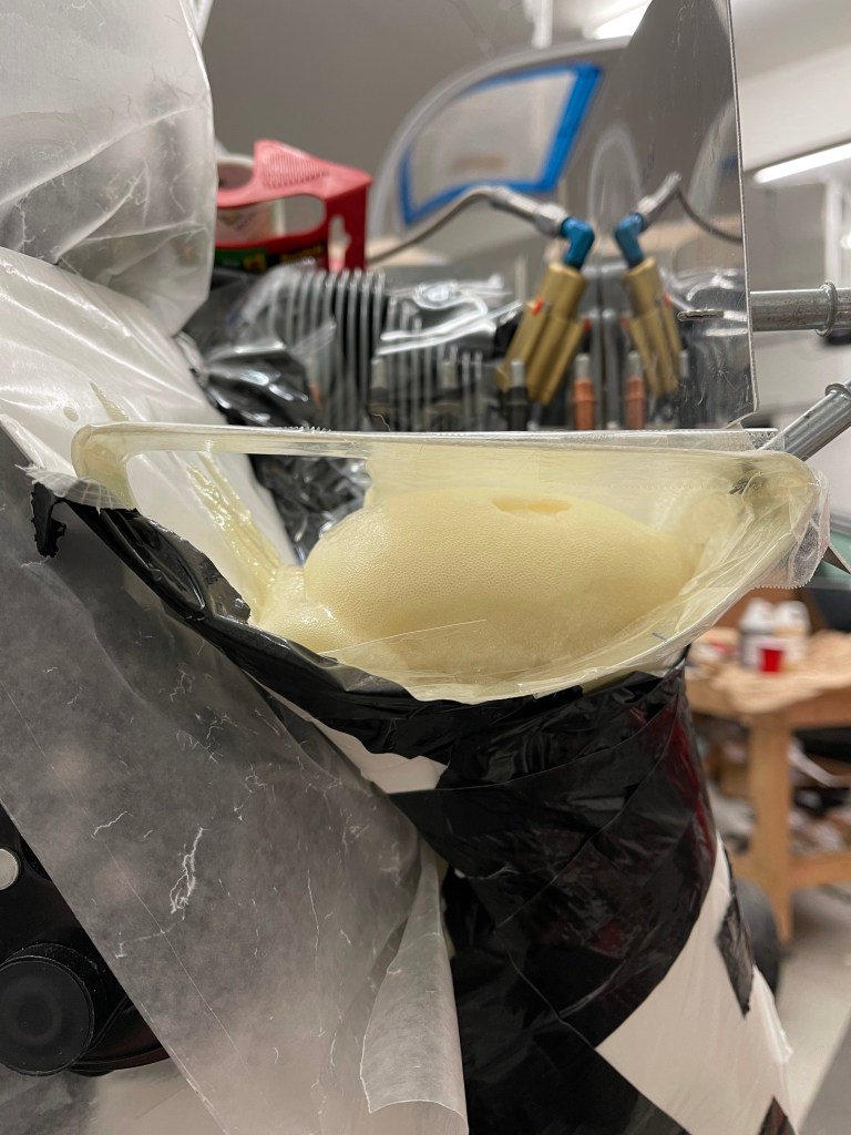
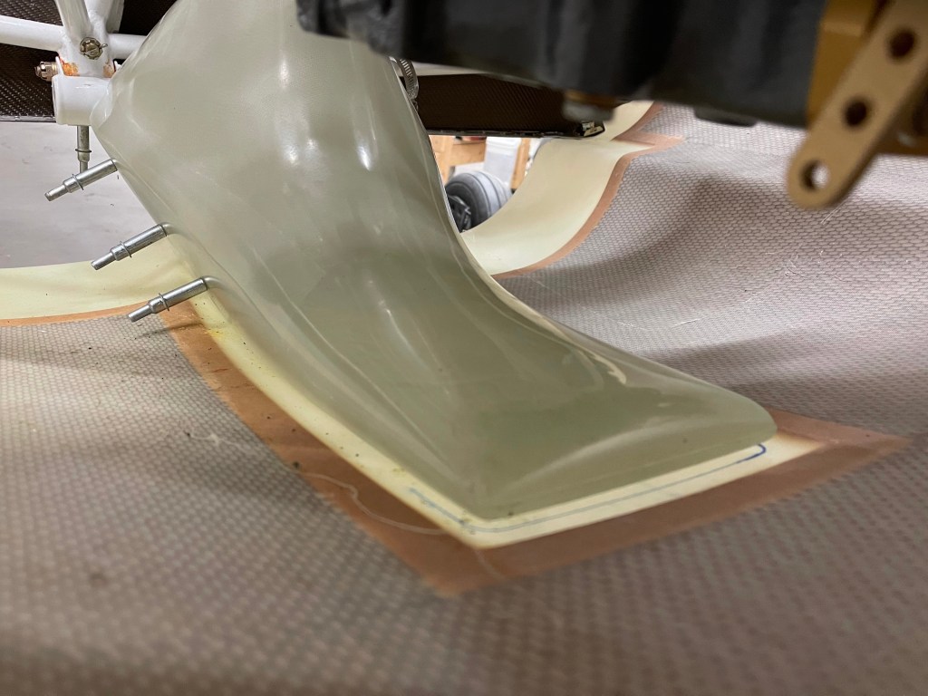
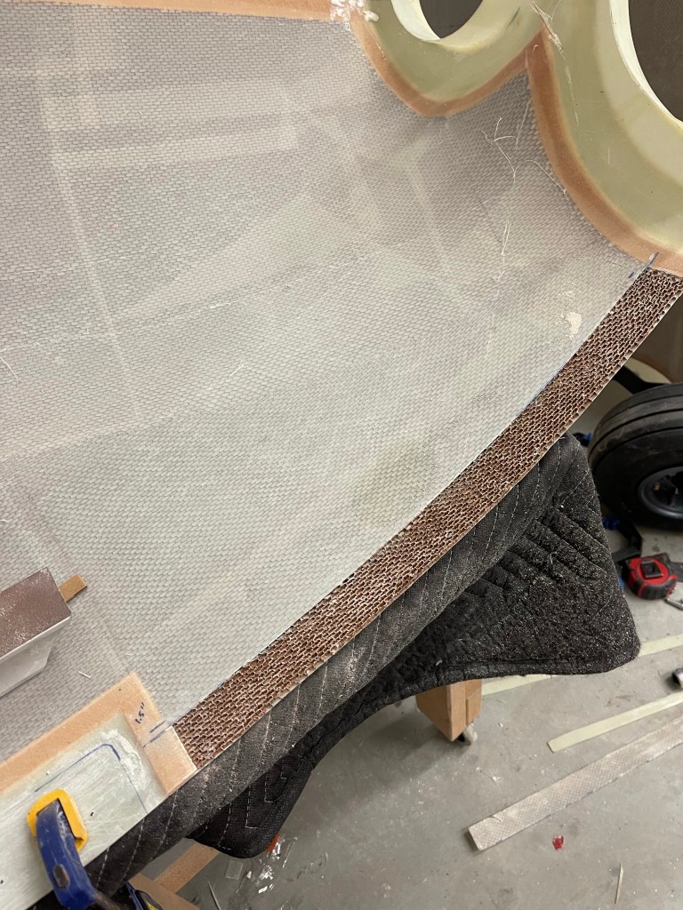
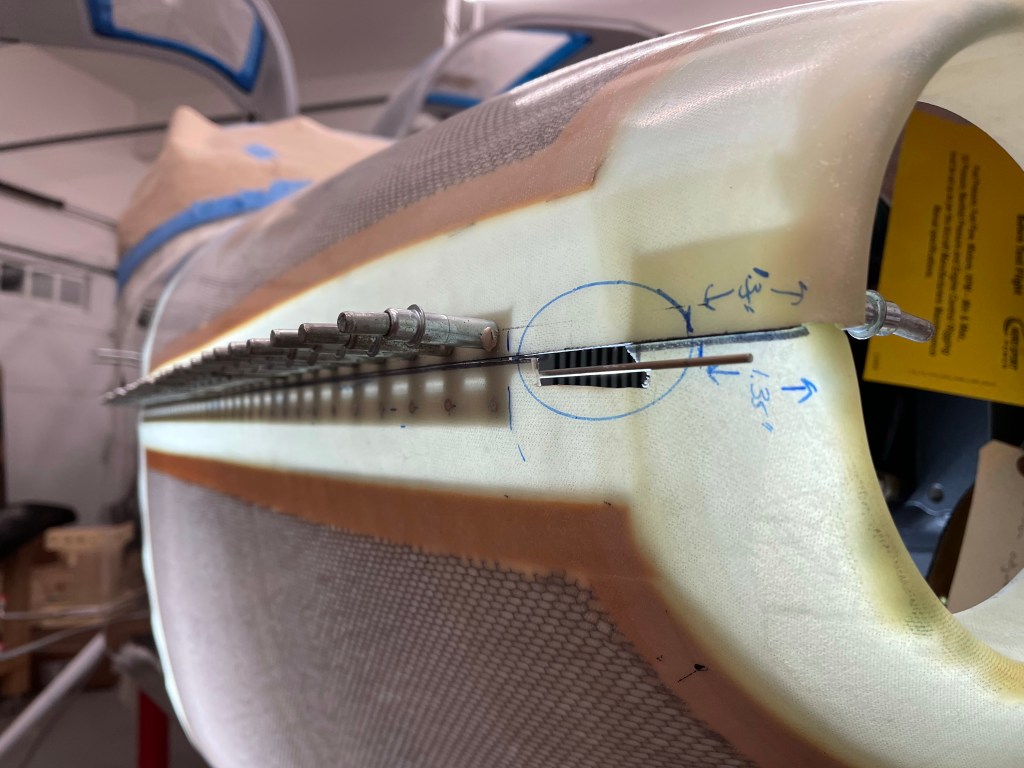
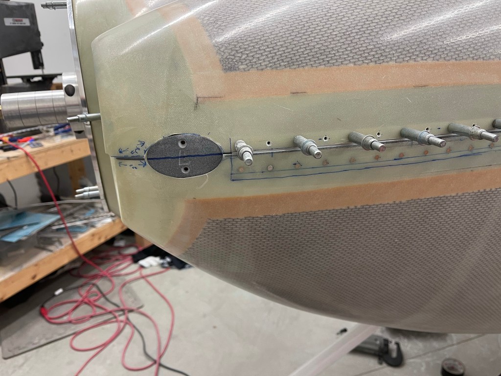
I finished it off with some micro and sanded it smooth.

With the pin inserted.

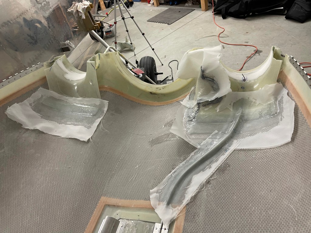
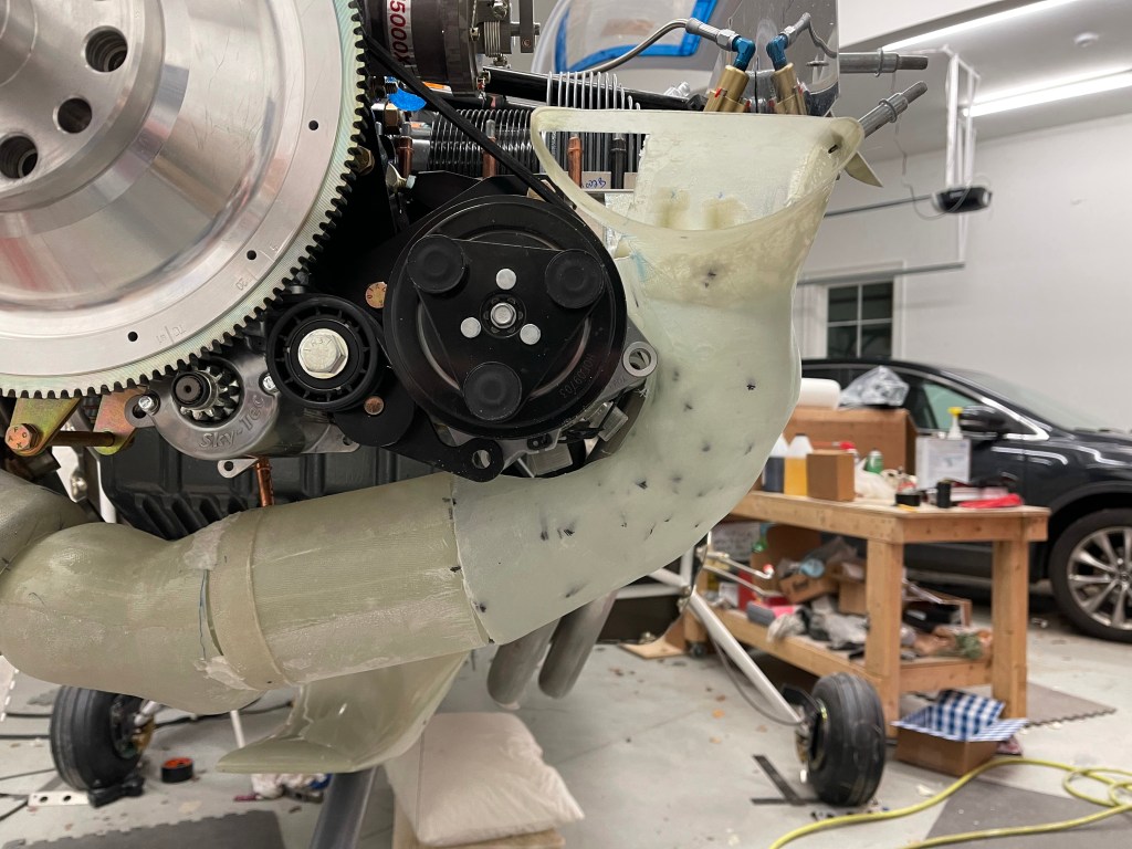
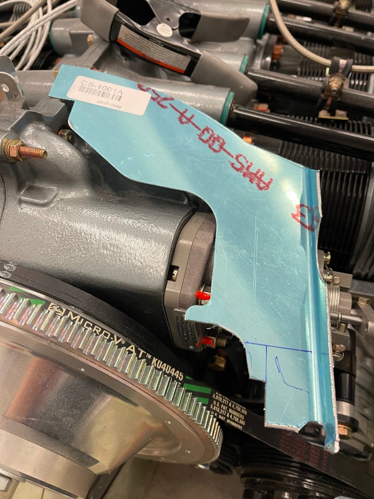
Another task I needed to figure out was how to feed air into the left side heat muff. With the AC compressor installed on the engine there is no good way to use anything from the air inlet area like the stock setup does. The only options I saw were to feed it from the aft baffle (like the right side does), feed it from the left intake snorkel, pull from the right inlet area (but this is also tight with the alternator over there), or add NACA vents to the lower cowl.

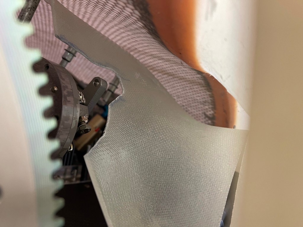
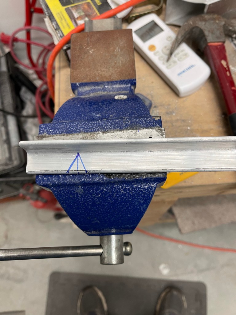
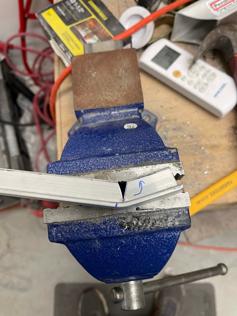
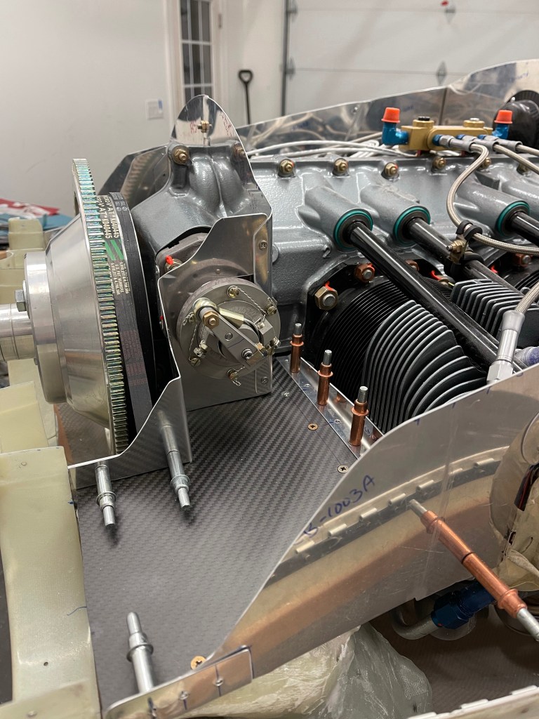
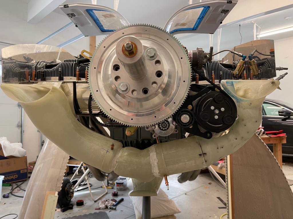
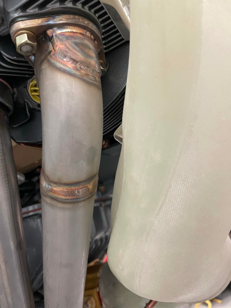
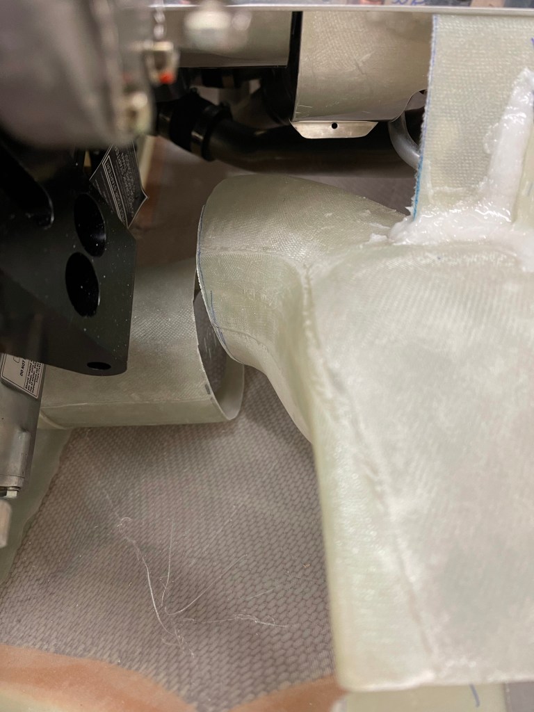
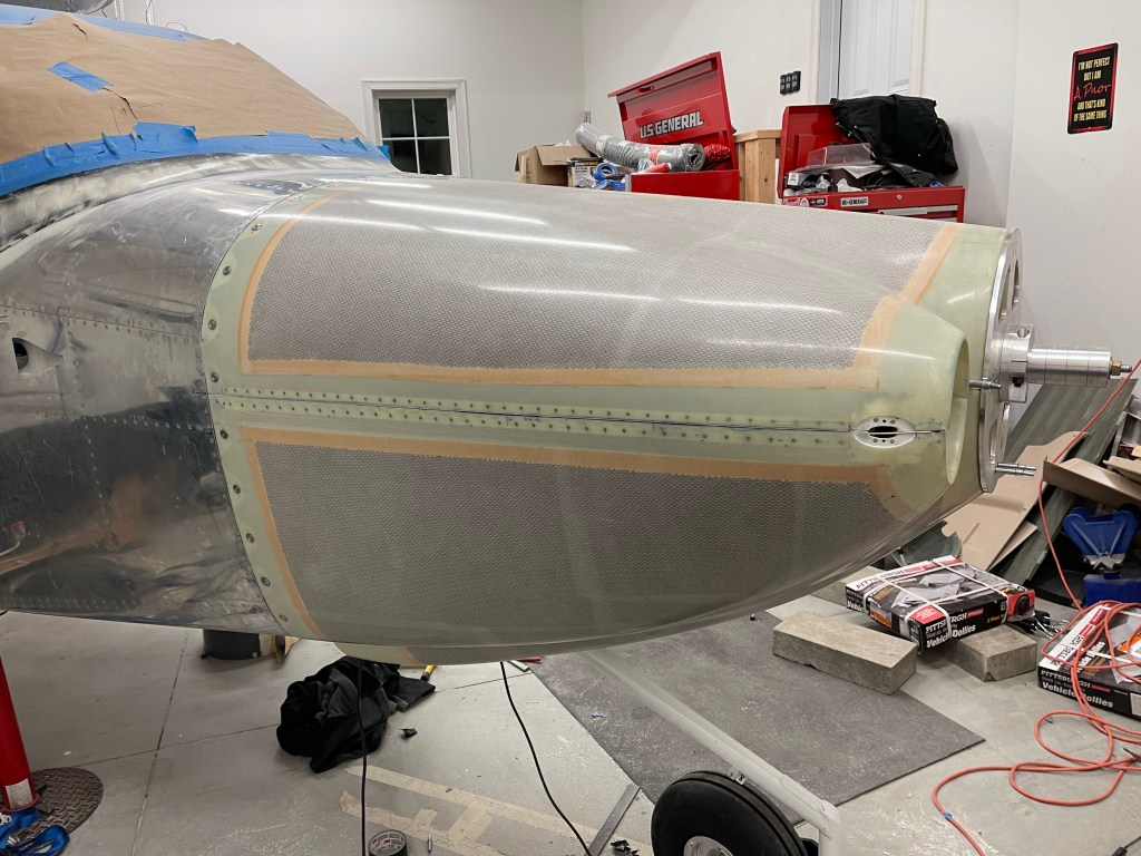
I’ve decided on pulling from the left intake snorkel. This does steal some combustion air , but the Showplane’s setup is designed to only need air from one side to be sufficient. So I will add a 2″ SCAT tube between the locations shown with arrows below. Of course, I’m going to need to get a 180* setup for the #2 cylinder heat muff from Custom Aircraft parts instead of the normal 62.5* one I have now. This will have air come in from the outside of the exhaust and intake tubes to the engine and the outlet will be on the inside of those tubes feeding the left heat box.

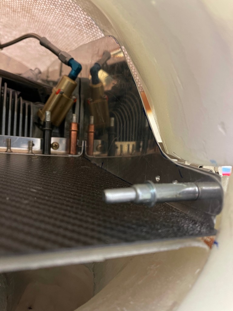
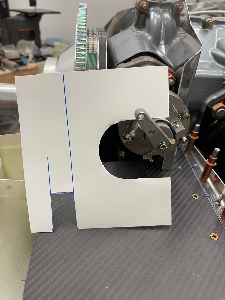
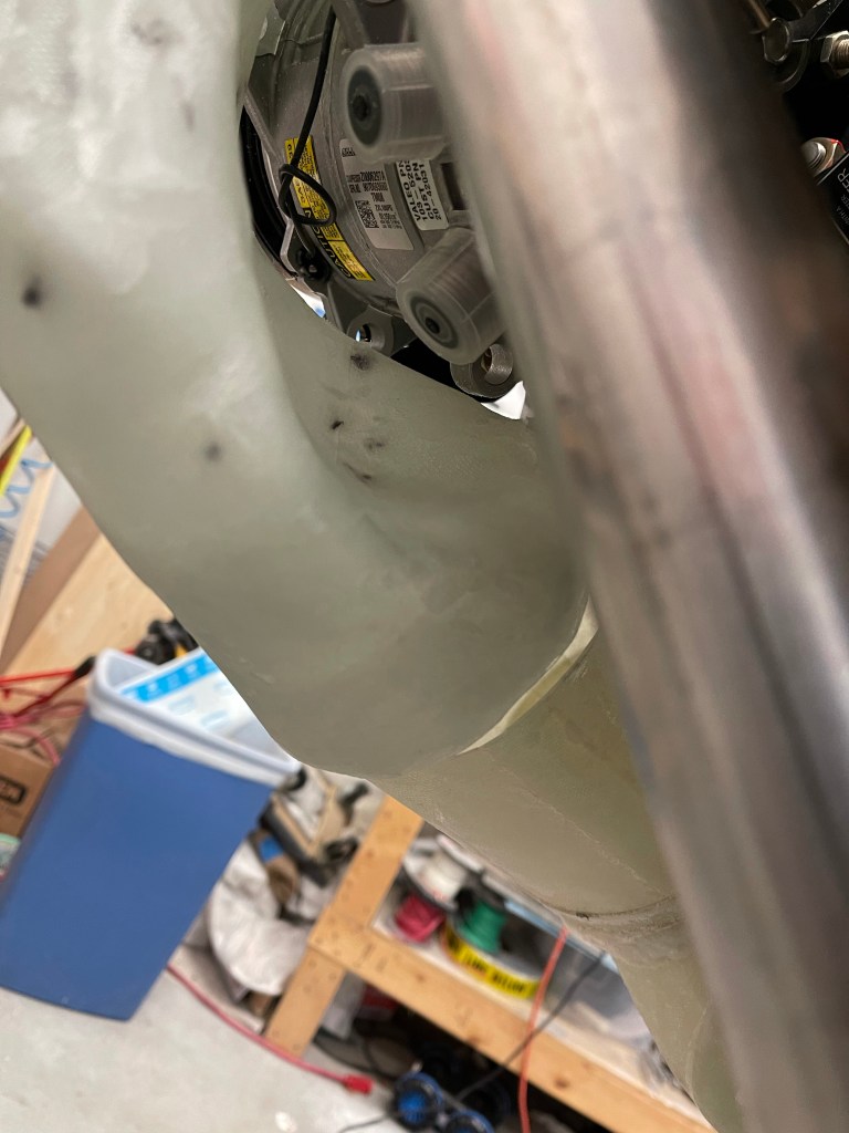
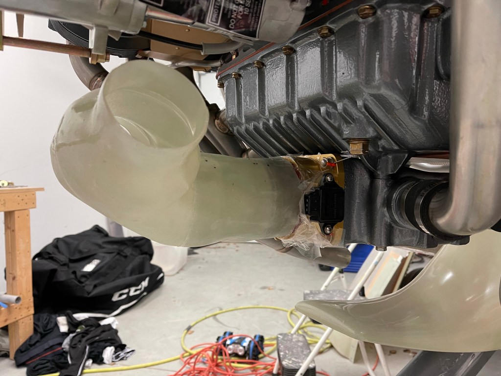
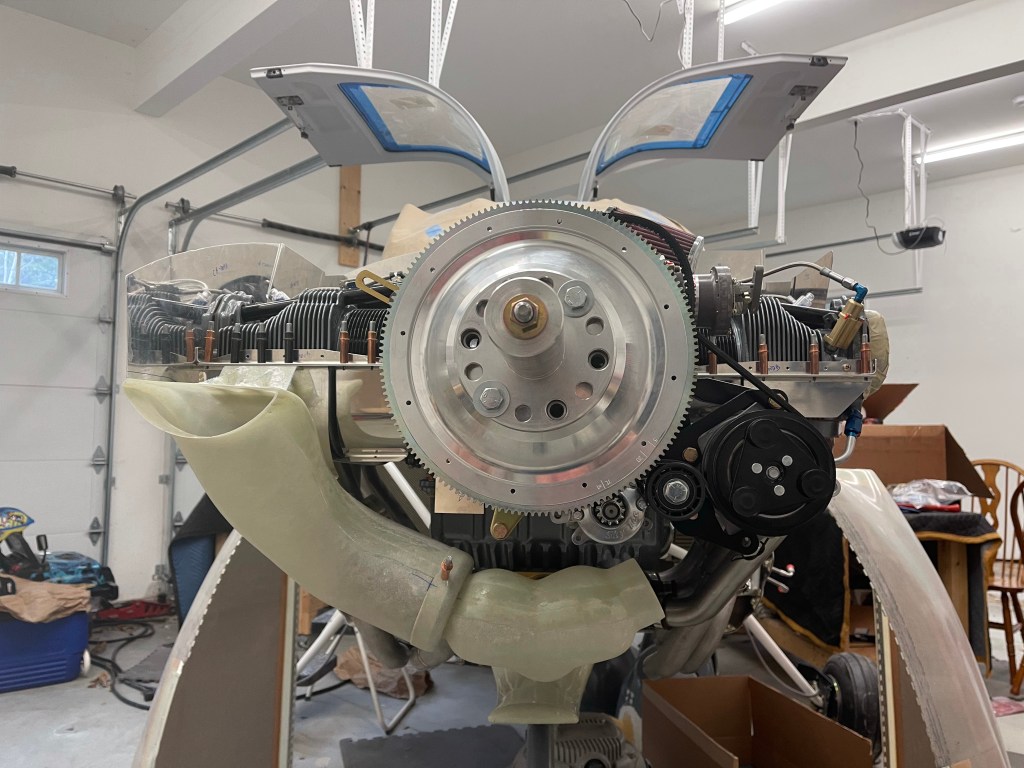
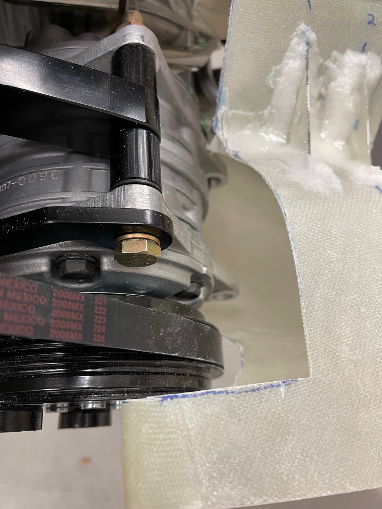
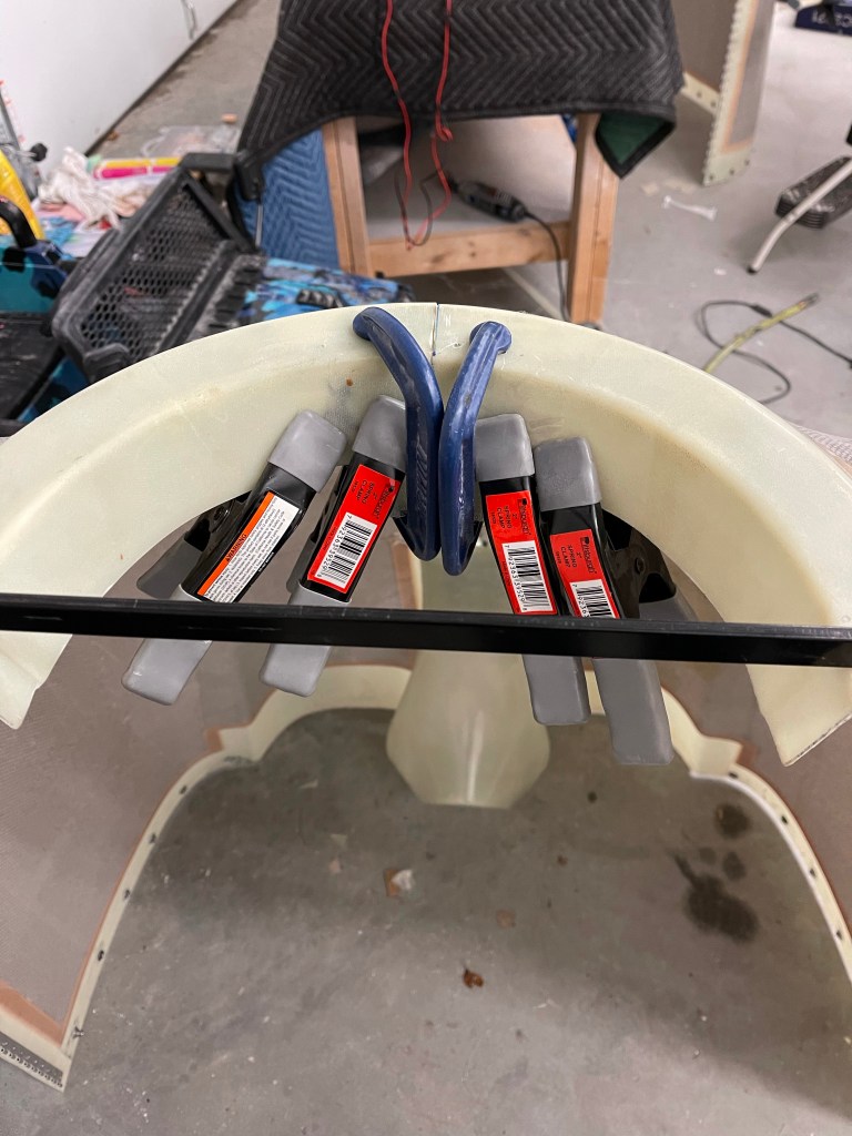
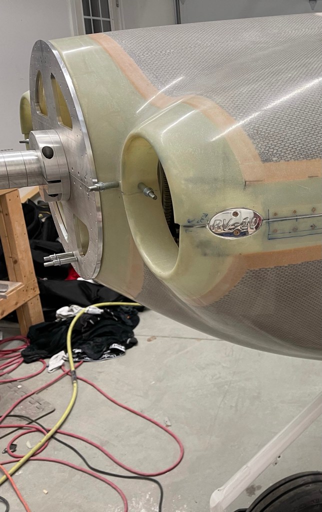
A rough mock-up of where the 2″ SCAT tube will go. There seems to be sufficient space between the lower cowl and the engine to do this.

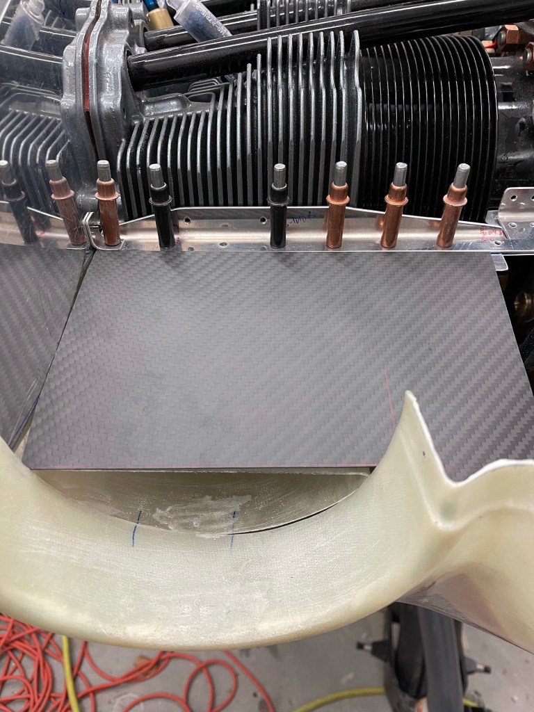
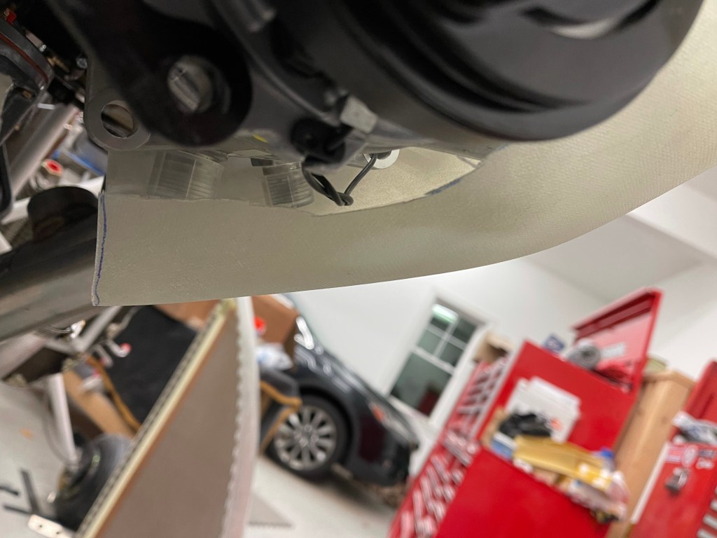
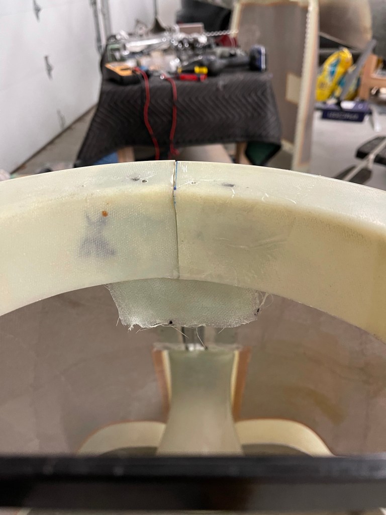
A rough approximation of where the inlet to the heat muff will be.

In talking to Clinton about this, he’s also been fighting some cracking in the exhaust on the left side. He had previously sent me a support setup for the exhaust to help with vibration, which I have, but haven’t done anything with it quite yet. He asked that I install my exhaust and check for any interference with the intake tubes and in the end, I’ll need to send my entire left side of the exhaust back to him for modification to help prevent cracking in the future.

Left side of exhaust installed.
Right side installed.

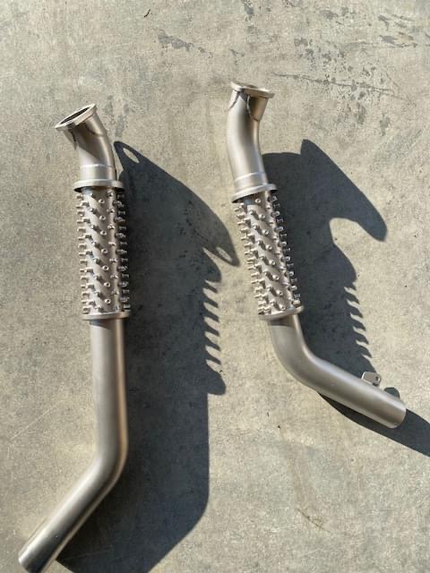
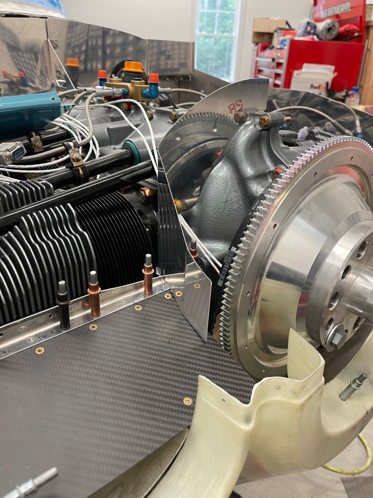
While sending it back, I’m also going to have him “stud” the heat muffs on both sides (as shown below) to allow for some better heat transfer. I didn’t know about this option prior to ordering and it apparently helps get some more heat for the colder months. The stock Vetterman exhaust is known to have too much heat, but that’s not always the case with the Custom system.

Picture of Bob Lusslow’s studded exhaust that I’m going to have done.

Finishing the hidden hinge oil door

During some down time with baffling tasks, I decided to tackle finishing off the oil door and its hidden hinge release method using a Bowden cable. I started by filling in the left side upper inlet with expanding foam to allow the baffling material in the area of the prop governor something to press against.

Initial foam fill and sand flat.

I then placed it on the plane and looked at the clearance to the governor arm. I sanded it down as a curve until I was happy with the clearance.

A test fit of the foam area

I then put the Bowden cable in place and got a rough idea of where the cable would penetrate the upper inlet ramp. I marked and drilled 2 holes on either side and then ran a 1/4″ drill bit through the foam to connect the 2 holes. I was then able to get the cable through.

Marking where the cable will go through and the rectangle is the area where the cable end will sit.
Cable in place left long on the cowl opening side.
A closer view

I then laid up 4 layers of cloth over the Bowden cable, the exposed foam to close it out, and the upper inlet ramps to better adhere them to the cowl per the Showplane’s instructions.

Fiberglass layup w/ peel ply

After curing the view of the results.. The cable is now permanently adhered to the cowl. I also cut the metal cable housing to length and bent the inner pin at 90* to get your finger on it.

A view aft to front

Then I took a quick video of how one opens the oil door. Closing is equally easy.. just hold the door down and push the pin back into position. I still do need to get some molding clay and make a small weathervane with a slot to house the cable end in the inlet area. This clay will be used as a mold to lay up fiberglass and allow it to cure.

Baffle trimming and intake ramp finishing

In order to get the top cowling back on, the baffle needed to be trimmed. I saw two ways to do this, and I ended up sort of using both. I started by elevating the top cowl 6″ above the lower cowl. Care was taken to make sure it was aligned both fore, aft, left, and right to the bottom cowl. I just used some pieces of scrap wood and clamps that I had lying around on each corner on the outside of the cowl. I measured in multiple locations along the horizontal split to be sure I was satisfied before moving on.

Cowl elevated 6″
More of a front view.

I then made a tool out of a tongue depressor and an aluminum block I had. I taped a sharpie to the bottom of the block and adjusted the stick to get exactly 6″ from pen to top of the stick. I didn’t take any pictures, but the idea here is that you have enough room (with the 6″ elevation) to get your hands/arms inside to hold the stick at a 90 degree angle with the sharpie along the inside of the baffle. Holding the stick on the inside of the upper cowl, you move it aft tracing the contour of the top cowl onto the baffle which will serve as a trim line.

I then trimmed to that line. That basically got me to flush. One could certainly add some extra to the length of the stick to get the the gap you’d like to achieve. Instead, once the initial trim was done, I utilized the 2nd method of paper clips all along the baffles. You barely stick them on and then place the top cowl into position. They slide downward and give you an exact indication of how much gap you have at that location to the top cowl.

Paperclips in position to measure gap

Below you can see the results of the first attempt. You’re shooting for somewhere between 12/32″ and 16/32″ gap per the plans. At each paperclip location, I wrote the number of 32’nds needed to get to 12/32″ by measuring how high each paperclip was above the edge of the baffle.

Measuring current gap

Those measurements basically were used to draw a new trim line.

Marking a more precise trim line.

I ended up doing this for a couple of cycles until I was completely satisfied with the gap all the way around. Making smaller adjustments in specific areas as I went. Below isn’t the best picture, but it was the results of the baffle trimming with a gap to the top cowl.

I fabricated the clips and drilled them into position per the plans. I’m holding off riveting most of this stuff until later.

Now that the baffles were trimmed, I decided it was time to affix the top cowl inlet ramps. I placed them into position with clecos and some scrap metal strip to hold them in place at the front.

I then test fit the cowl and had to trim the outer side baffles more to account for the curvature. I did get somewhat lucky due to my cowl being so far forward based on my prop/spinner setup compared to most. The ramps didn’t require trimming at the prop governor to at least test fit. I did end up trimming around to give some more clearance, which I’ll foam in later to provide a good backing for baffle material.

No initial trimming required for prop governor.

Once I was happy with their location, I epoxied them into place. Later I will layup some cloth, but for now just epoxy to hold them in position. I also did a single layer of cloth and some peel ply on the inlet circle just to hold that area into position.

Epoxy ramps into place.
1 temp layer of tape with peel ply on the outside.

I then laid up 3-4 layers of cloth for the underside of the circular inlet.. Placed that into position and let it cure. I sanded down the outside area and added micro. Once that was cured, I sanded to a smooth finish.

Right inlet ramp micro’ed
Same on left side.
Cutout for prop governor

With the upper ramps completed enough for now, I moved on to customizing the center baffles. I started with the right side, seeing it’s the easier side without compressor interference to deal with. I cut the stock baffle leaving just enough flange to rivet a new piece that would angle toward the inboard side of the inlet. I first made a template from construction paper and got it as close as I could. I transferred to metal and worked on trimming to get a good gap to the upper inlet ramps.

Paper template of right side.
Transfer template to metal and test fit.

I then spent some iterations trimming this custom piece to match the curvature of the upper inlet ramp with some gap for baffle material. Below are the results.

Right center baffle gap.

To hold the inboard side in place I fabricated up some 3/4″ x 0.125″ Angle. Seeing there was a slight bend in the baffle I just created near the inlet, I marked a cut to match that bend in the angle. I marked and cut out a “V”

Marking the cut to bend the angle
Cut made.
Bending the angle to match the bend in the baffle.

Below is the end result after match drilling and cleco’ing the baffle to the angle.

I utilized 3 screws to tie the aft piece of metal holding the carbon fiber ramp to the front pieces, including the piece of metal that runs under the carbon fiber ramp. I trimmed the excess away on the inboard side of any carbon fiber and metal plate so it didn’t protrude past the angle.

I then did a similar thing using a template on the left side. I decided to use one piece of metal to wrap around the governor and bend around the AC compressor belt to box it out of the inlet area.

Beginnings of a paper template

Once I was satisfied with the paper template, I transferred it onto metal, cut it out, and made the needed bends as shown below.

Initial trim of the custom left baffle.
A front view.

I then worked to fabricate another short piece of angle with a notch cut out for AC belt clearance to hold the inboard side in place. I drilled 2 holes for #6 screws to attach to the stock baffle that I had cut off and left a bit of a flange for connecting my custom piece to.

View of left ramp area with baffles screwed together and cleco’ed to the angle
Front view showing the angle and 2 #8 screws holding it in position, allowing clearance for the AC belt.
View of the finished up left ramp area.
Both ramp areas complete (beside riveting everything).
Final picture with top cowling in place.

This was a lot of work!

Intake part 2

Now that the basic shape of the left intake tube was formed, it was time to sand it down to perfect shape. I used mostly the Permagrit sanding blocks for this task, and it was relatively easy. Of course, at some points I had to put the lower cowl on to make sure I had clearance to it. I also carved out a bit more in the back for the AC hose connections to the compressor.

Foam sanded to shape

I then laid up 4 layers of cloth and put some peel ply over the top and let the tube cure overnight.

Of course prior to doing this I covered the foam in packing tape as a release agent and also sprayed some silicone based release agent on that for good measure.

Once cured, I removed all the foam inside of the tube and test fit it.

I then cut some cloth to close out the top part of the tube where I had cut for clearance to the compressor. 4 layers again were laid up and peel ply placed over the top.

Closing out the top of the tube.

Once cured I test fit the tube once again to make sure things looked good. below you can see the blue sharpie lines that I used to mark the cloth for cutting pieces to shape.

Tube clearance to compressor
Aft view of bump in for AC hose connections
Closer look at the bump-in.

Then it was time to wrap a single piece of cloth to span the gap between the two tubes to join them back together. You can see the black line I marked for alignment. I also used a jack to allow the tube to sit on vs. having gravity pull down on the tube while this was curing. I used a single layer on the outside, because clearance to the cowl is a bit tight. Once this cured, I placed a thick layer of flox on the inside of the tube to fill the gap and create more strength in this area.

re-joining the tubes.
Complete except for some sanding.

One of the other tasks that needed to be done was to redesign the air ramps seeing I’m using the Showplane’s cowling and the stock metal ramps were cut out for this intake system. I fabricated a .032″ thick piece wide enough to go under the baffle angle and still protrude enough to serve as a flange for the new ramp. This will be bent downward somewhat depending on the angle between this and the from of the intake. It’ll provide a nice flat surface for attaching the ramp material to with screws.

I also bent up some of the side baffle material to provide 1 screw location. I also decided to fabricate up a metal piece that sits up front on top of the intake area. It has a bent flange that will rivet to the side baffle material. I’ve left everything to the inside (closest to the flywheel) long for now. Once I get the center baffles completely figured out this area will be trimmed and I suspect some aluminum angle will be used with some screws to connect the front metal piece to the aft piece I made with screws.

Picture of ramp area prep for screws and carbon fiber ramps.

I then cut some carbon fiber material I bought for the ramps to fit in the ramp area. Again, leaving the inboard side long for now.

Test fit right ramp material

I then match drilled everything, added nut plates, and screws to hold everything down.

Right Ramp.

I put the center baffle material in place after cutting it somewhat. This will need to be angled back towards the intake opening. In fact, I may cut the piece coming out towards the flywheel and rivet in a new piece of my own at an angle to achieve this.

Right Center baffle piece in place

I really had to trim away the left center baffle piece. It interferes with the AC compressor quite a bit. So I decided to cut the forward most section completely off, leaving enough material to rivet more metal to later, and also the notch for the aft part of the prop governor. Later, I’ll work on a custom piece to go over the prop governor and along the ramp to the intake area.

Working on the Left center baffle
Match drilling the hole for the 2 center baffles.

The same process was repeated for the left, with the exception that the compressor complicates the ramp..

Metal flange for ramp added

I decided the best way was to use construction paper to create template prior to attempting to cut the carbon fiber piece.

Creating a template
Transferring template to carbon fiber.
Ramp cut and in place.
Another angle
Bending up the side baffle for a screw location.
Ramp in place!
Another view. Looks like a #6 nutplate made it into my #8 bin.. I’ll have to fix that at some point..
All finished up with the left center baffle in place.

Air In…Take 1

The next area to tackle was the air intake system of the Showplaces cowl. Fiberglass tubes were supplied which take up the bottom 1/4 of each round air inlets on either side of the cowl. These tubes house air filters (one on each side) and join together with a servo plenum. The plenum connects to the SDS throttle body.

These intake tubes cause several deviations including the bottom inlet ramps needing to be completely cut away. I spent some time getting the inlet ramps cut to match the baffle stiffeners on the front of each side of the engine.

Right baffle stiffener
Left baffle stiffener

I then started to try to get the servo plenum and right intake into position. There are no obstructions like the AC compressor on the right side, so it’ll be the easier side to start with. I did have some trouble getting the plenum onto the SDS throttle body. It’s the correct size (3.5″ ID), but just didn’t want to easily slide on. Bryan at Showplanes suggested cutting 3/4″ slots at the 9 and 3 o’clock position, which is what I did.. That seemed to work better and still gave a nice tight fit.

double checking the ID of the servo plenum.
Plenum didn’t want to slide onto throttle body inlet.

Once I got the servo plenum in place, I quickly noted two things

  1. The left side air filter and tube in general is going to have major conflicts with the compressor and the 2 hose connections coming off the bottom of it. This was mostly expected based on builders that have gone before me.
  2. Due to my cowl being shifted forward quite a bit based on my prop/hub combo.. the servo plenum will need to shifted forward as well and an extension made to mate up with the throttle body.
Left side Air Filter will cause issues with A/C compressor
Need to shift the whole thing forward to get the inlet just behind the cowl opening

I wrapped some packing tape all around/over the throttle body and did a layup of 4 layers of glass to create an extension for the servo plenum.

Letting the extension cure overnight.

Once that cured, I worked on properly positioning the right intake tube. This was fairly straightforward and didn’t require any cuts or mods to do so.

Positioning the right intake
Rough gap to cowl.
A view from below.

One of the other benefits to my cowl being so far forward, is that the intake tube didn’t need to be modified to clear the #1 exhaust pipe. Below is a picture of the intake tube in place and you can see the stock bump in for clearance. Many other builders had to cut this area out and bump inwards more.

Clearance to #1 exhaust

It was then time to use the provided fiberglass sheet to secure the top part of the intake tube to the baffle stiffeners. I cut a piece wide enough to capture 3 of the holes in the baffle stiffener, enlarged to accept #8 screws. Some triangular pieces were also cut to strengthen the joint as these two pieces are bonded together. I also used a piece of aluminum to hold the intake in place while the flox was curing. Also of note the side baffles needed to be trimmed to match the curve of the intake

Getting ready to bond the two pieces together.
Flox on and curing overnight.

The right side was then mostly complete.

Right side mostly done.

I then experimented with some ideas for the left side. Through some reading and asking around.. it seems several builders that have a Showplane’s cowl and AC compressor have chosen to run unfiltered air for the left side seeing there is significant conflict in this area.. I wasn’t too thrilled with this idea.. As once you’re running unfiltered, air will take the path of least resistance and all go through the unfiltered route.. why bother putting in redundant air feeds in this case at all? Although I suppose it would still allow for an alternate air path in the case one side got blocked. I explored some options.. the one I settled on was to adjust the left side to angle the filter downward (more horizontal). Below you can see my attempt at looking at this from a clearance perspective to the AC.. Of course, you also have to balance that against the space you have to the lower cowl..

Filter more horizontal idea.

I marked out lines to basically cut the left side off entirely. I also cut the neck down off as indicated by the right-most lines (well the left-most (bolder) set of the right lines), to allow the filter to re-attach to the stock flange and not have to fabricate something up myself. This is basically cutting 2″ out in the middle and re-attaching the flange back to the plenum.

Marking out the cuts to make to the left side.

What I found was that if I slid the flange part onto the end cap and placed that whole “sub-assembly” onto the servo plenum, it wasn’t too bad of a size mismatch. I taped this up initially to look at clearances prior to floxing the whole thing together.

Filter, flange and end cap taped into place on plenum
Clearance to AC and hose ends
Finally checking clearance to the lower cowl.. There’s plenty!

I took the plunge and cut the servo plenum.. Hey it’s just fiberglass and I can fix it (I suppose) if I mess it up really badly.. 🙂

Floxing it all back together. I’ll eventually sand this down and probably lay a layer or two of cloth over this area.

I then followed the same procedure as the right on the left side (with the compressor removed for now)… I did, however, decide to cut the tube in the middle because of the angle being way off due to my previously described cuts to the plenum.. I chose to insert the tube into the filter end and cut it so that its length is just beyond the filter. Again no need to try to fabricate up a new piece to fit into the end cap when I’ve got a perfectly good piece to do so already.

Aligning and floxing the left side
Cut of the tube just at the end of the filter.

I then made some relief cuts to the inlet area around the compressor. Both at the intake area and down the length of the tube.

Relief cut

Looking at the angle of this tube relative to the compressor connections.. it was clear that not even this cut will work and cutting more will just cause a very thin tube.

Another angle of the initial relief cut.

It was at this point that I decided it was probably best to just fabricate a new tube between the intake piece and the filter piece. I cut the intake piece up a little closer up at the widest part of the tube.

Cut off the intake piece

In order to fabricate my own tube.. I decided on using a high density expanding pour foam. To do that, I used poster board covered with wax paper and a bunch of duct tape to form the basic outline of what I was after. This tube would connect the 2 pieces together. The liquid foam would be poured into this and it would expand out to fill out the tube.

Posterboard tube

I tested out a very small mix of the expanding foam with Declan. He was pretty excited about the experiment. First the foam I ordered.

I mixed up a very small amount and we witnessed how much expansion happened. Pretty cool!

Declan and I cut up the foam once cured (about 15 minutes) and he was happy stacking the blocks we created.

After that experiment Declan was exited to get to work on the foam for the airplane.. So I mixed up an initial batch which seemed to fill up the tube pretty close to full.

After first pour.

You can see the foam found its way out the plenum side too. Of course I put a cap on this filter side, so it wouldn’t go inside the tube.. This excess will easily be cut/sanded away.

The end result of the second pour.. I captured a short video of the liquid expanding in the tube.

Final pour results

After everything was cured.. I took the poster board off to see the results. Seems pretty good.. Lots of sanding left to do to make this a much smoother tube. Once that is done, I will lay up cloth over the foam to form the custom tube.

Hidden oil door hinge

In order to have a nice smooth and clean looking top cowl with no fasteners, I’m doing a hidden oil door hinge for opening. I utilized a spring based hinge so the door will pop open and stay up when opened.

Spring hinge

The first step was to trim the oil door on the scribe lines that came with the Showplanes cowl. This piece matches the curve of the cowl perfectly.

Marking the scribe lines

Then I marked out a 3/4″ line for a flange on the recessed part of the oil door location. A small amount of sanding was needed to have the door fit in the recess area. You can see the door fitting nicely below and the marks for the flange behind it.

Oil Door fit and flange marked.

I cut the recessed area carefully and seeing it also follows the curves of the cowl, I used it as a stiffener on the back side of the oil door. I utilized flox and drilled a bunch of holes (which will be filled in later) to make sure there was a good bond between the two. I also used clecos around the perimeter to makes sure the door held tight to the cowl during cure.

Door stiffener curing

I again used some flox and some packing tape to fill in the gaps between the spring hinge and the oil door. The hinge sat an an angle and it required a bit of a buildup to fill in the gap.

Flox filling in the gap under the hinge

It was then time to work on the opening hinge mechanism. I utilized piano hinge for this. On the oil door side it’s just wide enough to allow the hinge to pass through the opening.. The mating side on the cowl is a little longer and I made it a little longer on the forward side, which required a little hogging out of the foam area around the oil door perimeter.

Below is a bigger view of the front cowl as I was prepping for drilling holes to attach the hinges to the cowl and oil door. I used the normal hinge pin for fitting as it’s slightly bigger than the bowden cable wire that’ll be used.

Below you can see all the hinges riveted and the Bowden cable roughy in place. This will ultimately be attached to the inside of the cowl and the pin cable will be cut so that the pin is just inside of the left air intake hole. I’ll be able to grab the pin and pull it causing the oil door to pop open once the pin has been extracted far enough. I’ll need to wait until I finish the air inlet ramps to complete the cable part of this.

Oil door complete for now

Prop has arrived!

I got an email that my prop was ready to ship from Florida.. So I wired the final payment and waited about a week before I got a call from the freight company to schedule delivery. The crate arrived unscathed.. and I opened up the front cover to take a look. It’s a thing of beauty.

MTV-9 Prop

They really do crate these things well. The prop was mounted to about a 2″ thick piece of plywood with nuts and washers. That was bolted to the crate. Below is a pic of the crate in reference to my garage door. It’s pretty big!

Empty crate

Later that night I set to work removing the prop from the crate and mounting it to the plane. I really wanted to see how it looked and also wanted to see how well the cowl fit and the gap between the aft part of the spinner/spinner backplate and cowl. Using the cowl tool was one of those times where you measure 10 times before you start to cut. I utilized my engine hoist and some straps wrapped around the root of 2 of the blades to lift the prop up while I lined it up and threaded the bolts into the flange. The end result is awesome, and I’m happy with how it looks and came out!

MT had advised to shoot for 1/4″ gap and had said that the spinner dome will overhang the backplate a little bit, so the gap will end up a little less. A bit bigger gap is also recommended for a 3 blade prop for getting the cowl on and off easier.. Of course that’s not as much of a concern for me with the lower half of the cowl split into 2 pieces.

In the end, all the measuring and use of the cowl tool placed where the spinner would be resulted in a consistent gap that I’m pretty happy with after fitting the cowl without the prop in my possession

Cowl to spinner gap

Lower Cowl Rejoin

Hinges were cut to mount to the newly created cowl flanges. Again, I tried as best as I could to shift the hinge eyelids so they wouldn’t be seen in the split.. Given the curve in this area, it wasn’t as easy as the horizontal sides, but I did the best I could. When I wasn’t able to maintain it I favored the front rather than the aft as that would be the area most visible.

Match drilling hinge to cowl flange

Match drilling the other half of the hinge was a little more challenging to hold the cowl in proper position. I opted to use the forward fairing on the aft part with the 8 clecos where screws will hold things together to line up the aft end. I also used a small piece of scrap metal drilled and cleco’ed to the spinner area to hold the forward part of the cowl in position. I also used some duct tape along the split itself and removed as I went and got more holes match drilled and cleco’ed.

Getting ready to match drill other hinge half.. gap not quite closed fully yet.

In the below pic, you can see the cowl match drilled from the inside and outside. I feel the split gap came out pretty good.

Outside view
Inside view

Then it was time to adjust the aft part of the hinge and cut an access hole for the pin to be inserted in a fashion similar to the Aerosport pin covers on the sides of the cowl. I placed this hole just forward of where the forward cowl faring ends and made it rectangular about the combined width of the newly created flange.

Hinge pin access hole.

I fabricated a rectangular aluminium cover piece to fit the gap using some scrap. I drilled 2 holes for #6 screws to hold this cover in place.

Test fit of metal cover plate

I then did the same as I did for the Aerosport pin covers.. I place the metal cover plate into place with some packing tape around it for a release agent, slobbered a thin layer of micro over the back side, then laid up 4 layers of 9 Oz cloth and let cure. Below you can see the result after removing the cover plate. The central area between the 2 holes (where there will be nutplates added) will be cut out so the pin can be inserted.

And finally a picture of the cover plate in place after installing the nutplates and dimpling for #6 screws.

Cover Plate complete

Prior to permanently riveting the hinges in place, I did a test fit of the entire cowl again to make sure everything still fit together well.

I copied what Dr. Mark had done to the forward fairing that attaches to the area of the cowl with no honeycomb and added a metal support piece along with 8 nutplates for #6 screws. This will provide a solid attachment point between the 2.

Adding a metal backing plate and nutplates
Plate completed.
Inside view of the plate.

One of the last things to do (also copying from Dr. Mark) was to add a flange at the spinner area to provide an additional screw point and to alleviate any play in this area. I added packing tape on one side of the cowl so the fiberglass would only adhere to one side and serve as a flange behind the other half. This tape was placed such that the cut line was covered. That way I didn’t have to deal with attempting to cut the cowl halves apart again in this area potentially cutting into the newly added flange.

4 layers of 9Oz. Cloth clamped into place and curing overnight.

Below is a crappy pic of the inside where I used some scrap fiberglass with packing tape wrapped around it to clamp the newly added cloth in place along the entire spinner area while curing. Also a picture of my ugly mug to prove I actually built this plane.. 🙂

Below is the end result of the added flange.. Excess still to be trimmed away.

Then it was time to put the cowl all back together for a final test fit with all the hinges and skybolts in place. The only thing left is to add nutplates and screws to hold the top and bottom cowls together at the air inlets as well as the spinner area.

Cowl all buttoned up.

A closeup of the new flange and where the screw hole will go

Now to start working on the hidden oil door.

Cutting a perfectly good cowl

With the Skybolts and horizontal split line with hinges complete.. I moved on to fitting the two fairing pieces that come with the showplanes cowl. I trimmed the aft fairing to have 3/4″ flanges and then marked the center point. Additional trimming was needed to clear the front gear leg to get the aft fairing into position. 3 holes were drilled into the bottom of the fuselage for now to hold this in place. Later I will install rivets for screws to hold this into position.

Once you’re happy with this you place the lower cowl back on and drill a couple of holes on each side to lock in the position of the aft fairing to the cowling.

Aft fairing in place and cleco’ed to the lower cowling

Side view of the aft fairing.

Then with the aft fairing and lower cowling back on the bench. The forward faring was placed into position and trimmed as needed to get a good fit with the forward fairing. Once satisfied, 3 holes were drilled on each side to hold the forward and aft fairing together.

The aft fairing was put back into place on the fuse, and the forward fairing was trimmed to clear the engine mount tubes until the drill holes on each side lined up.

Front and Aft Fairing.
Front fairing fitting around the tube just below the donuts.

Once that was done, the lower cowl was put back into place to verify and adjust fit. The forward fairing needs to lay flat across the area of the cowling that has no honeycombed and be as centered as possible.

A decent fit to cowl.

I then had to add some fiberglass back to the slot that I had cut to get the lower cowl into position. I was careful to not cut too much when I did this originally, but I still cut a little too much. I sanded the edges at an angle to create a scarf joint with a fiberglass layup over the small area that needed to be added back. I put some peel ply on and let it cure overnight.

Adding material back to the nose gear slot.

The end result was pretty good.. There was a small gap in the rounded edge, which I later filled in with epoxy and let cure and sanded down.

I then sanded the inside of the cowl at the scarf joint that I added. You can see that below just about done.

Sanding the scarf joint.

I then put the lower cowl onto some cinder blocks so I could level it as needed. I used the laser level to make sure the intakes were level horizontally, which the vertical was aligned to the center line of the lower cowl.

The center line was marked with a sharpie as well as some blue painters tape. I also marked out the locations of 8 holes to drill into the forward fairing that will hold the cowl to that fairing with screws. I also mapped out 8 additional holes that mostly go through the aft fairing into the cowling.

The lower cowling was placed back on and the hole locations were match drilled to the forward fairing

Then the big moment came.. Using a diamond cutting wheel on a dremel tool to cut the lower cowling in half!

For whatever reason, despite having a plan… it seemed scary to me to cut this perfectly good cowling like this…

The cut will later be rejoined with another hinge pin like the horizontal sides. Skybolts could also be used here, but I opted for a hinge for a better look.

To prep for that hinge.. I marked out a 1.5″ wide rectangular area at the split point. I again used the diamond wheel on the dremel tool to just cut through the inner layer of fiberglass as shown below.

Cutting the inner fiberglass only. prepping for a flange buildup.

I then used a flat blade on a Dremel multi max oscillating tool to separate the honeycomb material from the inner layer of fiberglass. Below you can see me mostly done separating the fiberglass layer from the honeycomb.

Inner layer of Fiberglass removed.

I then used a chisel to carefully remove the honeycomb material. You have to use caution as the remaining fiberglass outer layer is very thin.

Using a chisel to remove honeycomb material.
Done removing honeycomb. Some additional sanding to be done still.

I then cut some strips of 9 oz. fiberglass to build up a flange where the structural material was just removed. I decided to use 6 layers of cloth for this. The end result was a thickness consistent with the other areas of the cowl that don’t have honeycomb.

6 layers of cloth in place
peel ply added.

Then after curing overnight you can see the results of the flange.

Next up will be re-combining what was just cut in half…

Cowling part 2

Indirect lighting from inside the cowl when drilling the skybolts can really misalign you. I started to also trace the inside of the hole with a fine point sharpie to get an even better view of exactly where the hole is and also use that to gauge walking the step bit in one direction or the other.

Even with that I’m ever so slightly off, although not by enough to matter.

Below is a look down the left side at the firewall with some skybolts installed. Here you can see my small light that I used taped in place to more directly illuminate the hole.

I then used a laser level to mark and trim the top cowling first. the 12″ Permagrit sanding block was used after getting close with a diamond cutoff wheel on the dremel tool.

I then used the top cut to mark out the bottom cowl cut location.

I trimmed close with the dremel tool and then used the sanding block to get it as close to perfect as possible.

Once that was done, I marked the location of the hinge pin covers from Aerosport. Location was based on the plans.

With the hinge pin covers located, I then got to installing the side hinges. I shifted the hinge downward so the eyelids won’t show. I used a AN257-P3 length hinge on the bottom cowl and a -P4 length hinge on the top cowl to get enough flange to maintain edge distances on both the hinge and the fiberglass.

Left side bottom drilled

The same was done on the right side.

Use of the laser level to get the rivets all aligned down the hinge.

One thing I did was to drill a couple of turns with a hand drill in each marked rivet location prior to using a higher speed air drill. This created a slight dimple so the high speed drill wouldn’t wander once I was drilling through. Very little pressure was used and just let the drill bit do the work.

A view of the right side done and hinge pin in place (not yet cut to length)

I then cut out the spot where the aerosport hinge pin cover template was to be placed. I got close and then used a file to get it to fit tightly in the cut hole.

I then followed the Aerosport directions and added tape and wax to the template along with putting a micro slurry on the inside of the area. I also wetted out 4 layers of 9 Oz fiberglass and placed it on the inside. Once cured overnight, I used a thin woodworking saw I had from a previous task of cutting casings to cut through the Aerosport template and separate the cowl halves. I will say that the very front part where the 2 cowl halves overlap gave me a lot of trouble as I bonded them together and it took a relatively long time to get them apart and left me very frustrated. There is not a lot of room to work either to try to use small files etc.. to chip away at the bond. So use caution when doing this with a Showplanes cowl.. It’s pretty easy to waste 3-4 hours hacking away to get them apart again..

The end result of the recessed area I built up in order to install nut plates for the cover.

The center area of the added fiberglass was cut out to allow the pin insertion into the hinge.

Finally the hinge pin cover was test fit into place. This is at such an angle that if the hinge pin were to start to wander forward with vibration, it would stop the pin from working its way further out as the pin would hit this metal cover. From all accounts that I’ve seen.. the pin doesn’t typically do that anyways, but it would only be allowed to move approx. 1″ forward worst case.