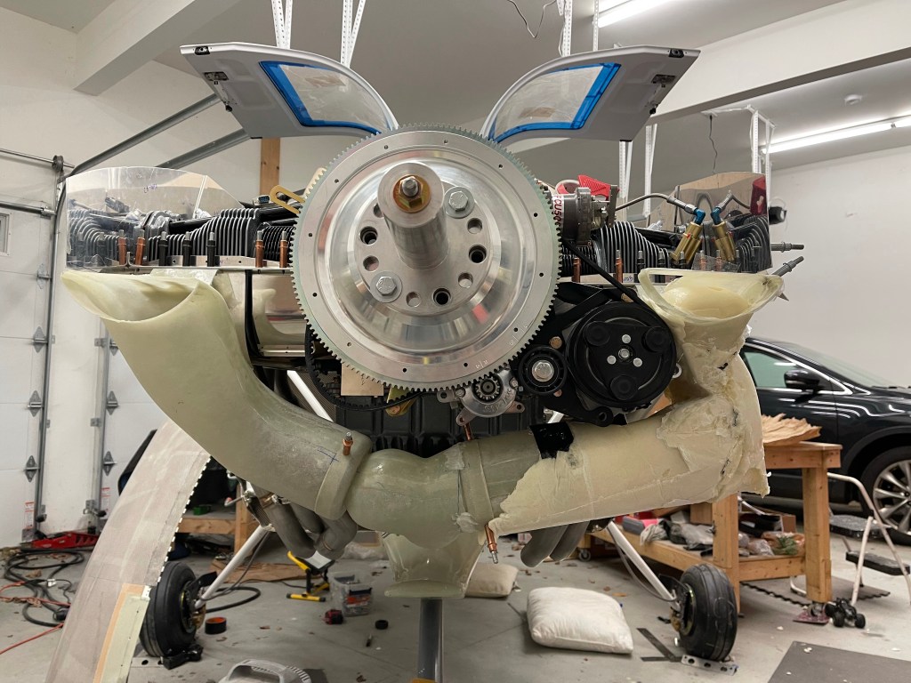
The next area to tackle was the air intake system of the Showplaces cowl. Fiberglass tubes were supplied which take up the bottom 1/4 of each round air inlets on either side of the cowl. These tubes house air filters (one on each side) and join together with a servo plenum. The plenum connects to the SDS throttle body.
These intake tubes cause several deviations including the bottom inlet ramps needing to be completely cut away. I spent some time getting the inlet ramps cut to match the baffle stiffeners on the front of each side of the engine.

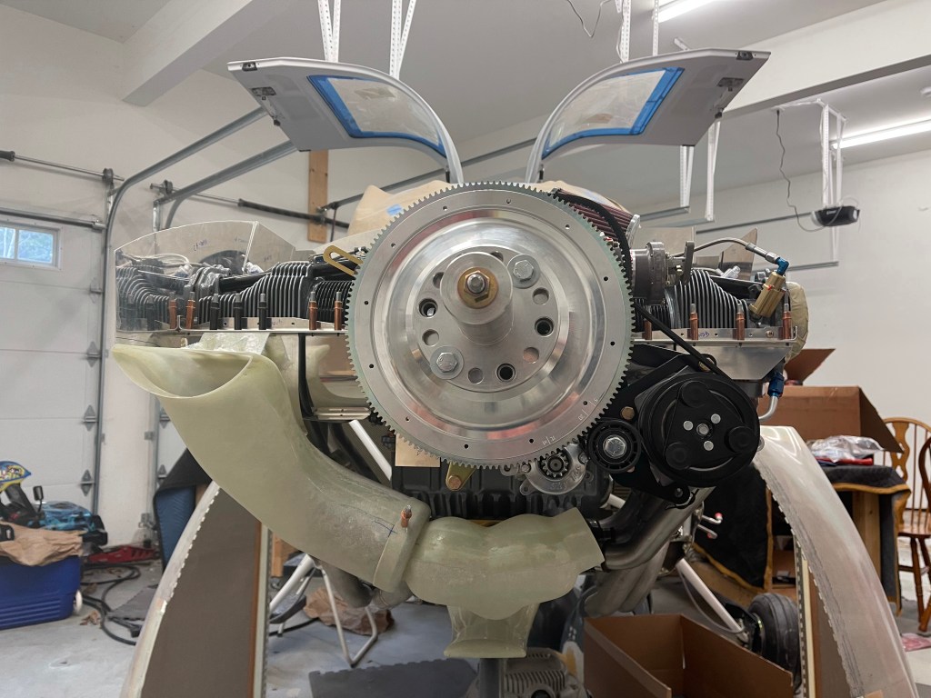
I then started to try to get the servo plenum and right intake into position. There are no obstructions like the AC compressor on the right side, so it’ll be the easier side to start with. I did have some trouble getting the plenum onto the SDS throttle body. It’s the correct size (3.5″ ID), but just didn’t want to easily slide on. Bryan at Showplanes suggested cutting 3/4″ slots at the 9 and 3 o’clock position, which is what I did.. That seemed to work better and still gave a nice tight fit.

Once I got the servo plenum in place, I quickly noted two things
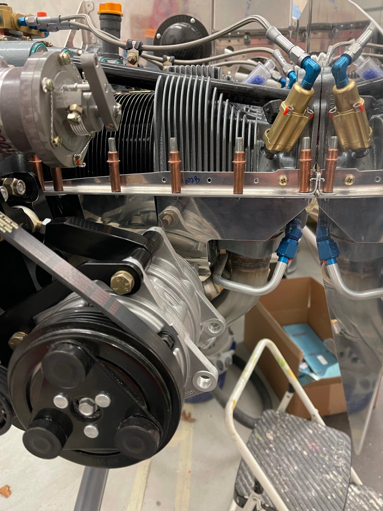
- The left side air filter and tube in general is going to have major conflicts with the compressor and the 2 hose connections coming off the bottom of it. This was mostly expected based on builders that have gone before me.
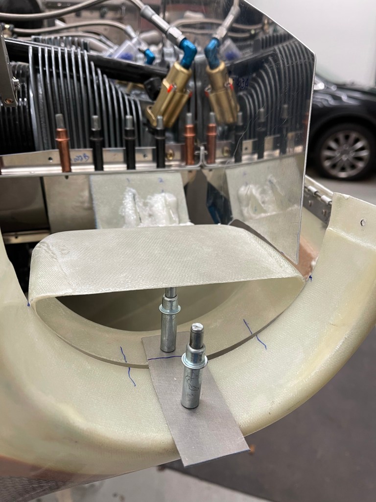
- Due to my cowl being shifted forward quite a bit based on my prop/hub combo.. the servo plenum will need to shifted forward as well and an extension made to mate up with the throttle body.


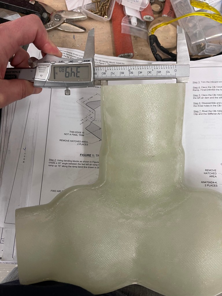
I wrapped some packing tape all around/over the throttle body and did a layup of 4 layers of glass to create an extension for the servo plenum.
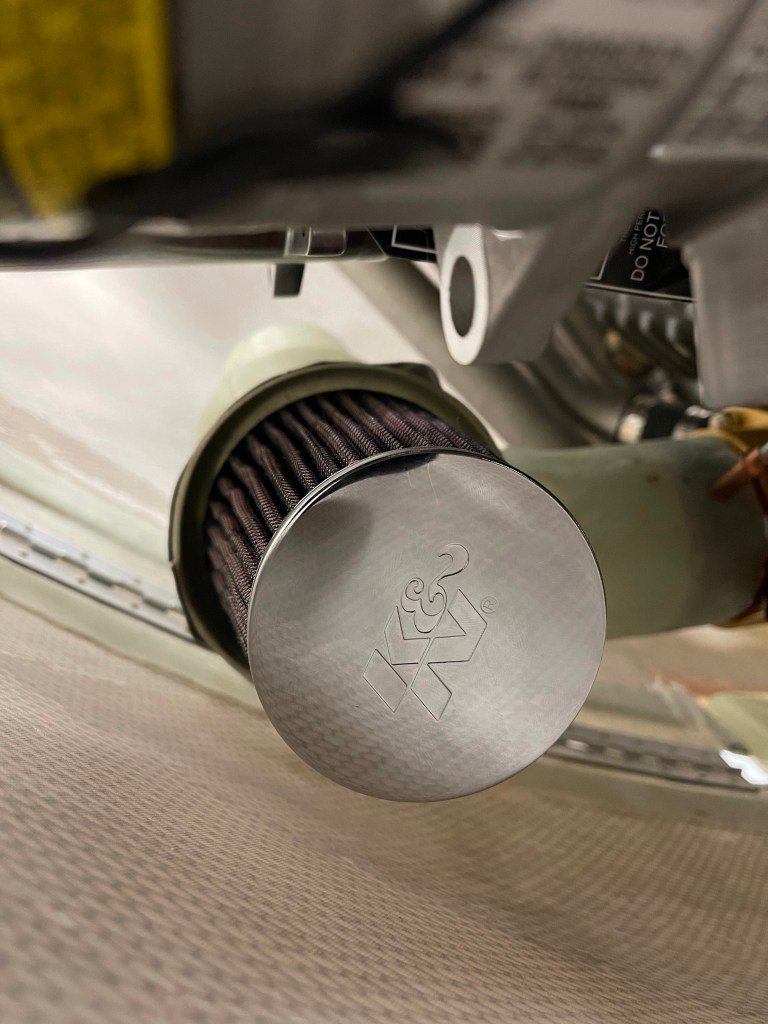
Once that cured, I worked on properly positioning the right intake tube. This was fairly straightforward and didn’t require any cuts or mods to do so.


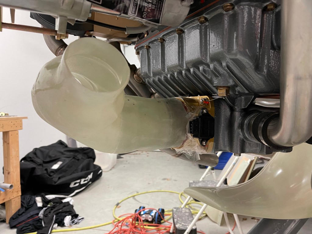
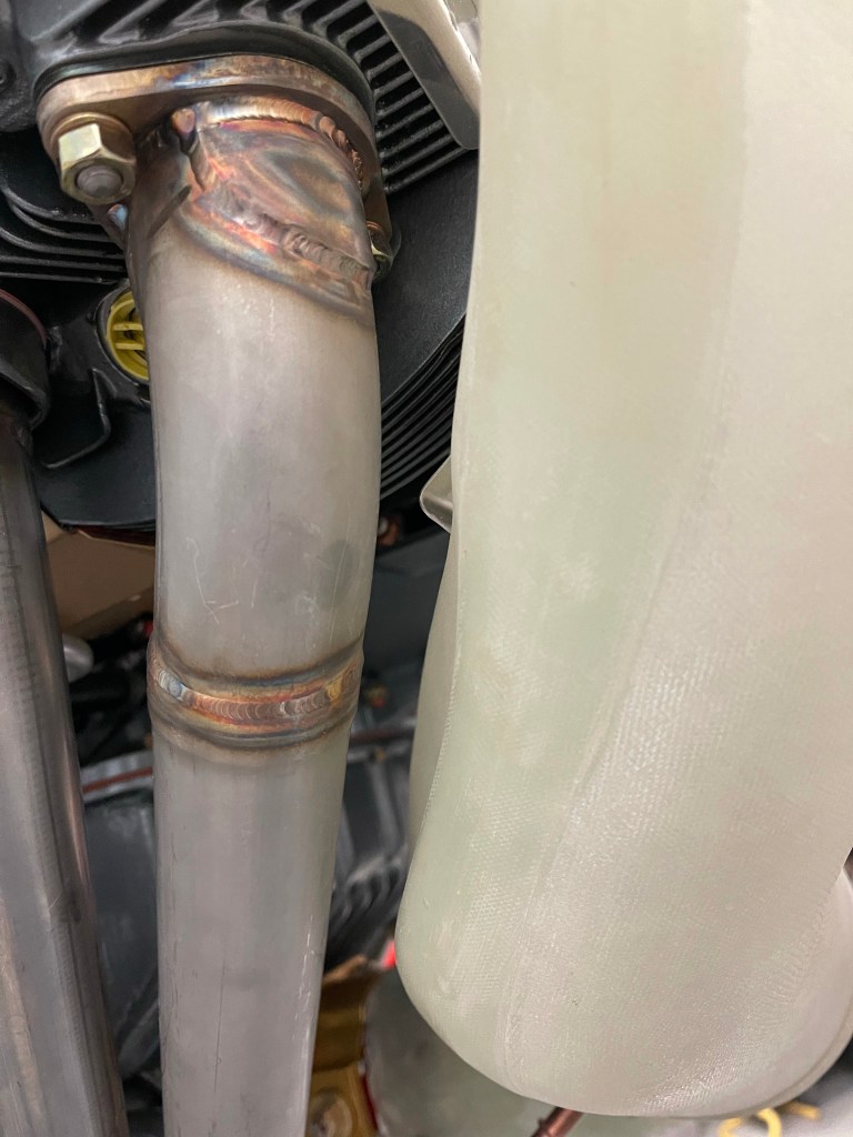
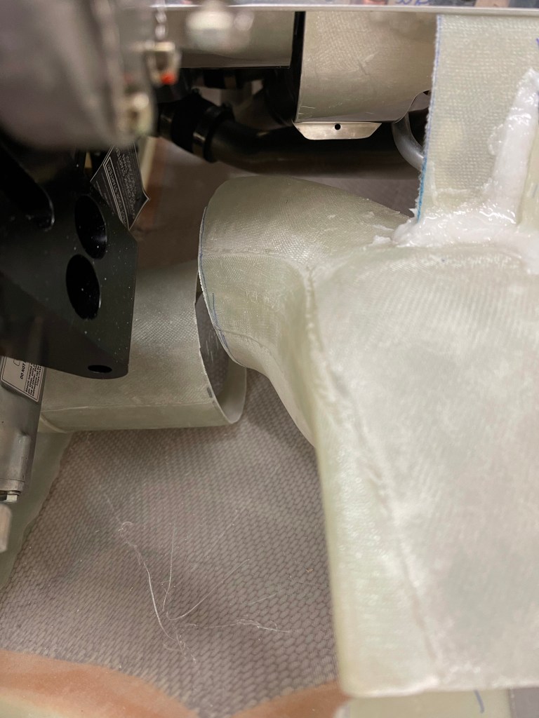
One of the other benefits to my cowl being so far forward, is that the intake tube didn’t need to be modified to clear the #1 exhaust pipe. Below is a picture of the intake tube in place and you can see the stock bump in for clearance. Many other builders had to cut this area out and bump inwards more.
It was then time to use the provided fiberglass sheet to secure the top part of the intake tube to the baffle stiffeners. I cut a piece wide enough to capture 3 of the holes in the baffle stiffener, enlarged to accept #8 screws. Some triangular pieces were also cut to strengthen the joint as these two pieces are bonded together. I also used a piece of aluminum to hold the intake in place while the flox was curing. Also of note the side baffles needed to be trimmed to match the curve of the intake


The right side was then mostly complete.
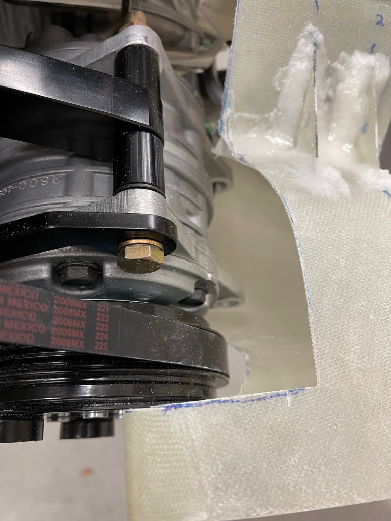
I then experimented with some ideas for the left side. Through some reading and asking around.. it seems several builders that have a Showplane’s cowl and AC compressor have chosen to run unfiltered air for the left side seeing there is significant conflict in this area.. I wasn’t too thrilled with this idea.. As once you’re running unfiltered, air will take the path of least resistance and all go through the unfiltered route.. why bother putting in redundant air feeds in this case at all? Although I suppose it would still allow for an alternate air path in the case one side got blocked. I explored some options.. the one I settled on was to adjust the left side to angle the filter downward (more horizontal). Below you can see my attempt at looking at this from a clearance perspective to the AC.. Of course, you also have to balance that against the space you have to the lower cowl..

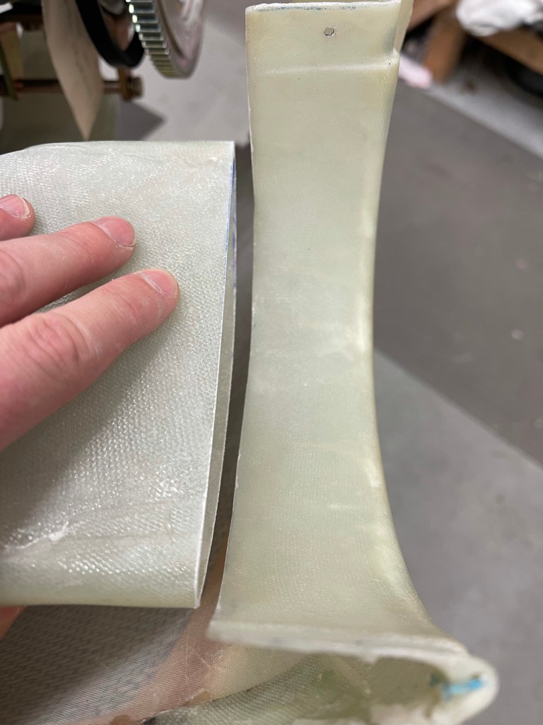
I marked out lines to basically cut the left side off entirely. I also cut the neck down off as indicated by the right-most lines (well the left-most (bolder) set of the right lines), to allow the filter to re-attach to the stock flange and not have to fabricate something up myself. This is basically cutting 2″ out in the middle and re-attaching the flange back to the plenum.

What I found was that if I slid the flange part onto the end cap and placed that whole “sub-assembly” onto the servo plenum, it wasn’t too bad of a size mismatch. I taped this up initially to look at clearances prior to floxing the whole thing together.


I took the plunge and cut the servo plenum.. Hey it’s just fiberglass and I can fix it (I suppose) if I mess it up really badly.. 🙂

Floxing it all back together. I’ll eventually sand this down and probably lay a layer or two of cloth over this area.

I then followed the same procedure as the right on the left side (with the compressor removed for now)… I did, however, decide to cut the tube in the middle because of the angle being way off due to my previously described cuts to the plenum.. I chose to insert the tube into the filter end and cut it so that its length is just beyond the filter. Again no need to try to fabricate up a new piece to fit into the end cap when I’ve got a perfectly good piece to do so already.
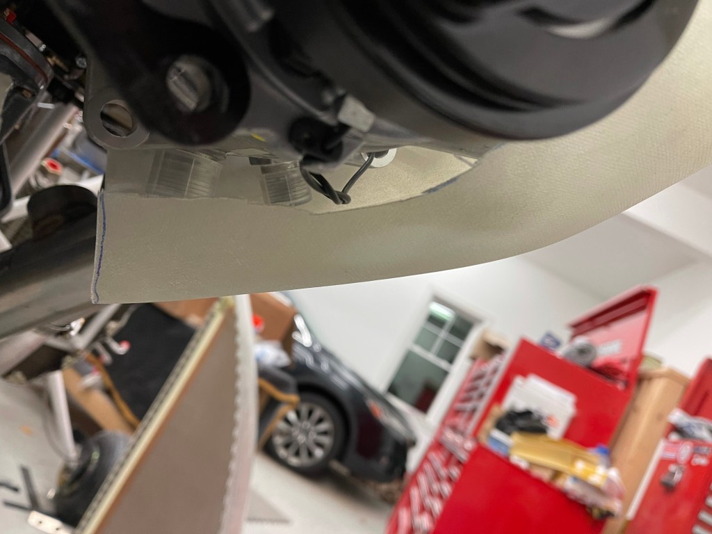
I then made some relief cuts to the inlet area around the compressor. Both at the intake area and down the length of the tube.
Looking at the angle of this tube relative to the compressor connections.. it was clear that not even this cut will work and cutting more will just cause a very thin tube.

It was at this point that I decided it was probably best to just fabricate a new tube between the intake piece and the filter piece. I cut the intake piece up a little closer up at the widest part of the tube.

In order to fabricate my own tube.. I decided on using a high density expanding pour foam. To do that, I used poster board covered with wax paper and a bunch of duct tape to form the basic outline of what I was after. This tube would connect the 2 pieces together. The liquid foam would be poured into this and it would expand out to fill out the tube.

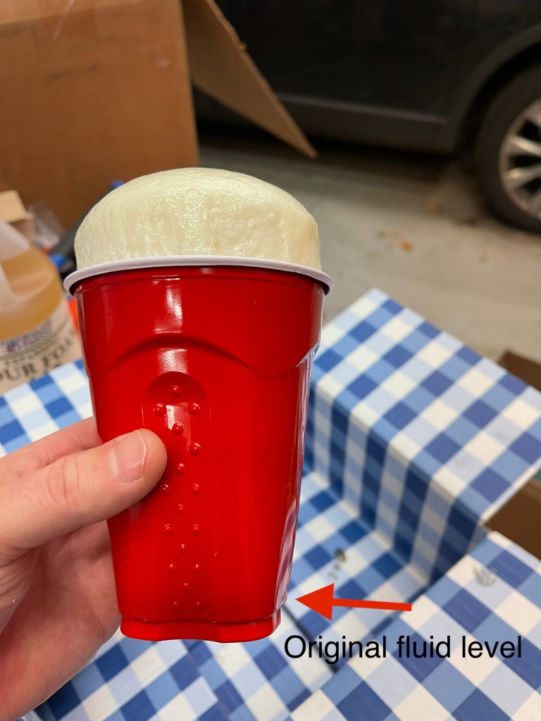
I tested out a very small mix of the expanding foam with Declan. He was pretty excited about the experiment. First the foam I ordered.

I mixed up a very small amount and we witnessed how much expansion happened. Pretty cool!
Declan and I cut up the foam once cured (about 15 minutes) and he was happy stacking the blocks we created.

After that experiment Declan was exited to get to work on the foam for the airplane.. So I mixed up an initial batch which seemed to fill up the tube pretty close to full.
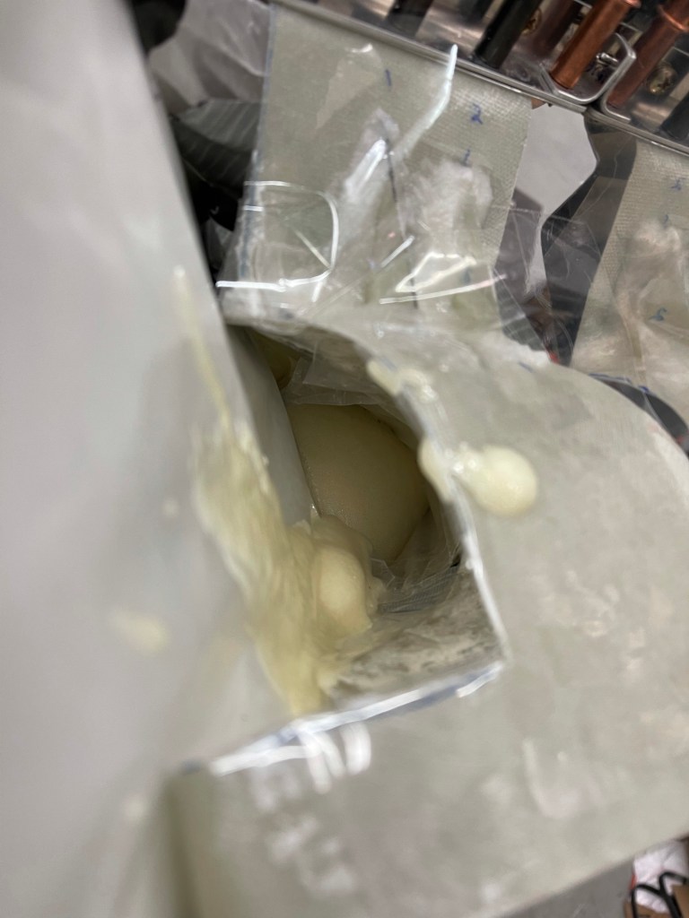
You can see the foam found its way out the plenum side too. Of course I put a cap on this filter side, so it wouldn’t go inside the tube.. This excess will easily be cut/sanded away.

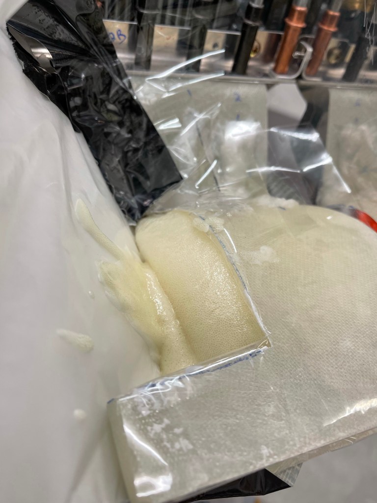
The end result of the second pour.. I captured a short video of the liquid expanding in the tube.
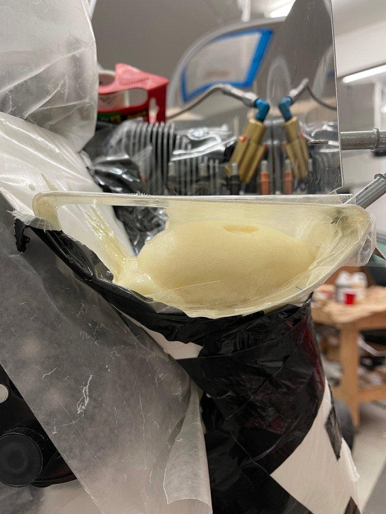

After everything was cured.. I took the poster board off to see the results. Seems pretty good.. Lots of sanding left to do to make this a much smoother tube. Once that is done, I will lay up cloth over the foam to form the custom tube.