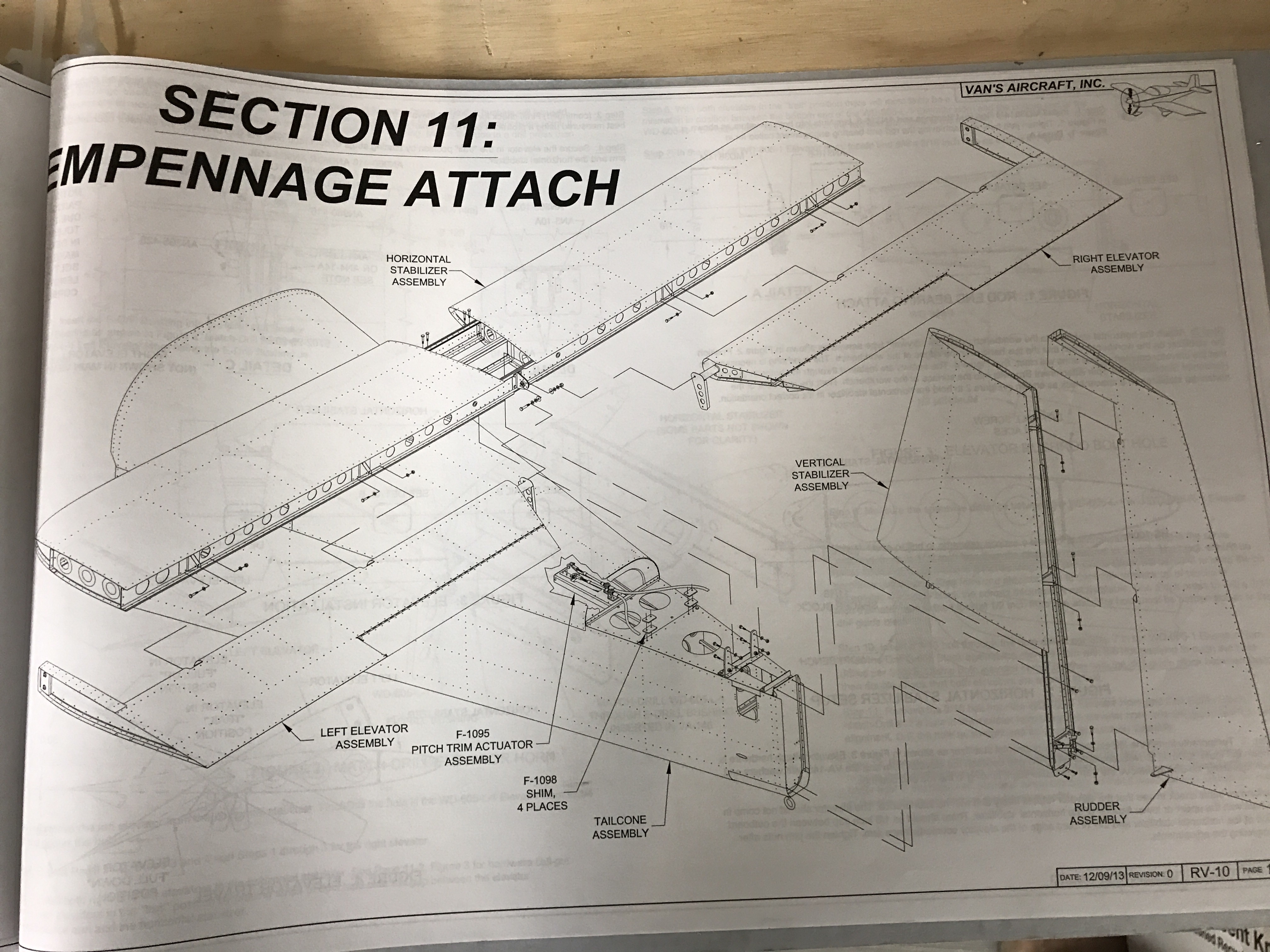
Lots of progress since moving to the hangar. It started by getting the tail pieces back on.
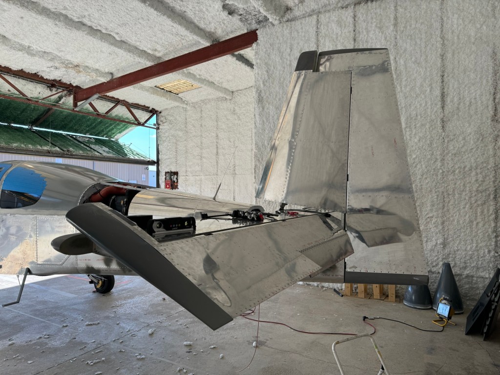
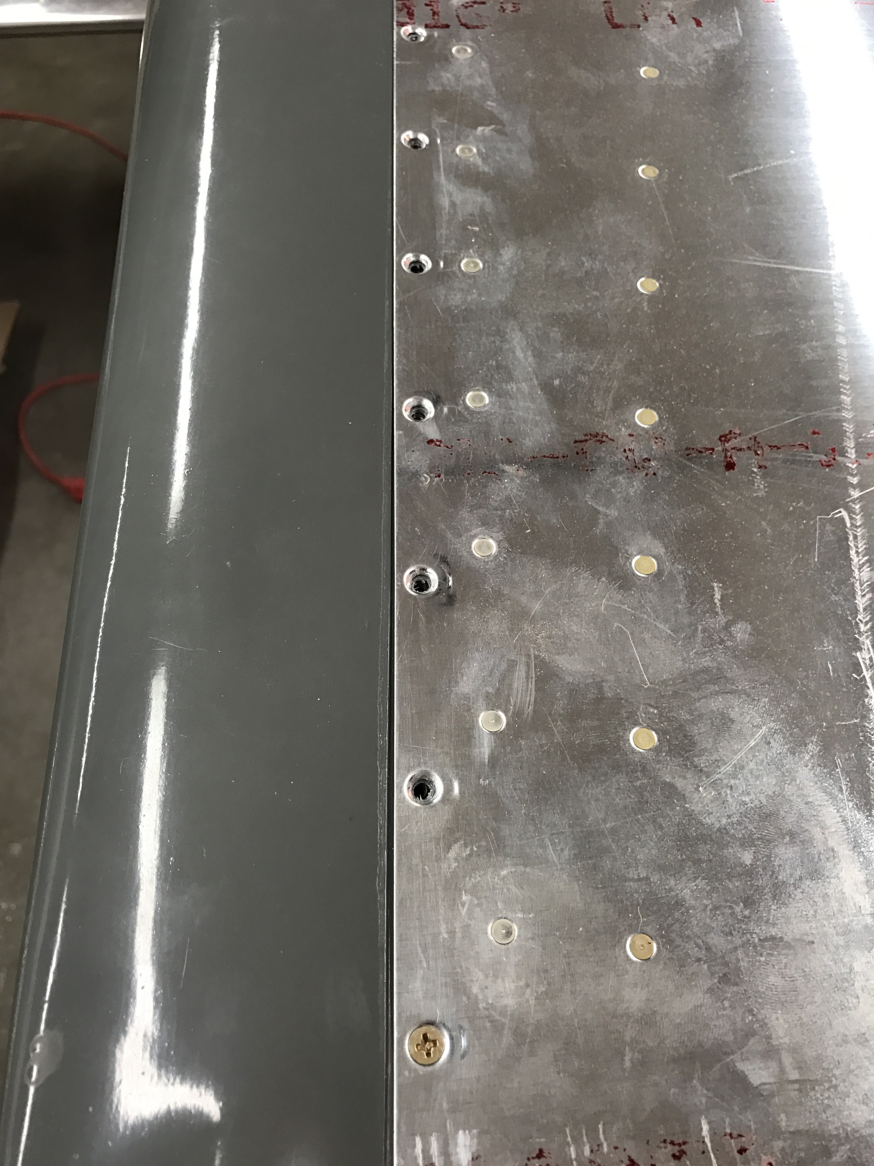
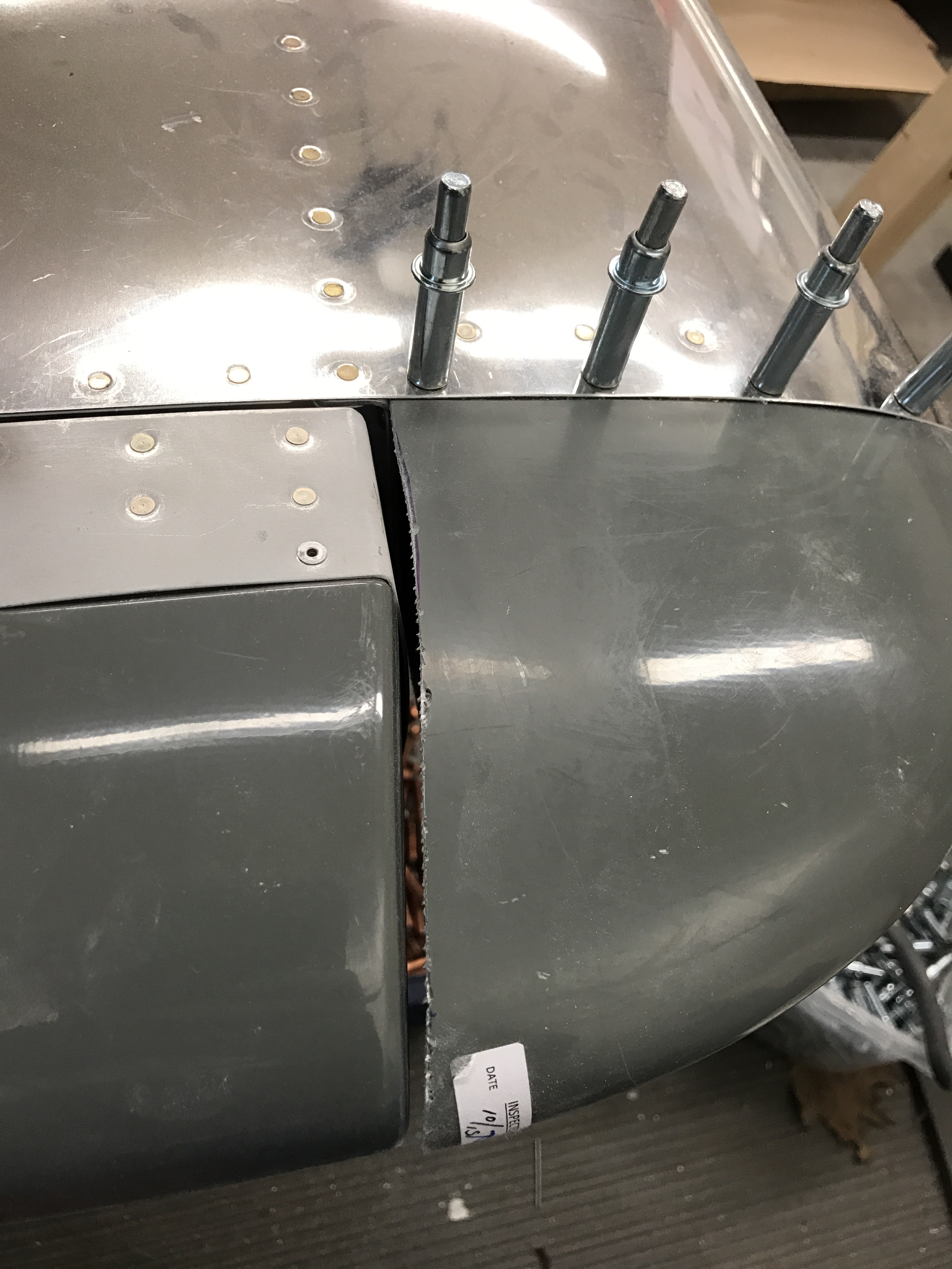
I then worked to get the emp fairing cover trimmed and in place and matched drilled to the holes in the metal using a strap duplicator. Then added nutplates so it can be held down with screws.

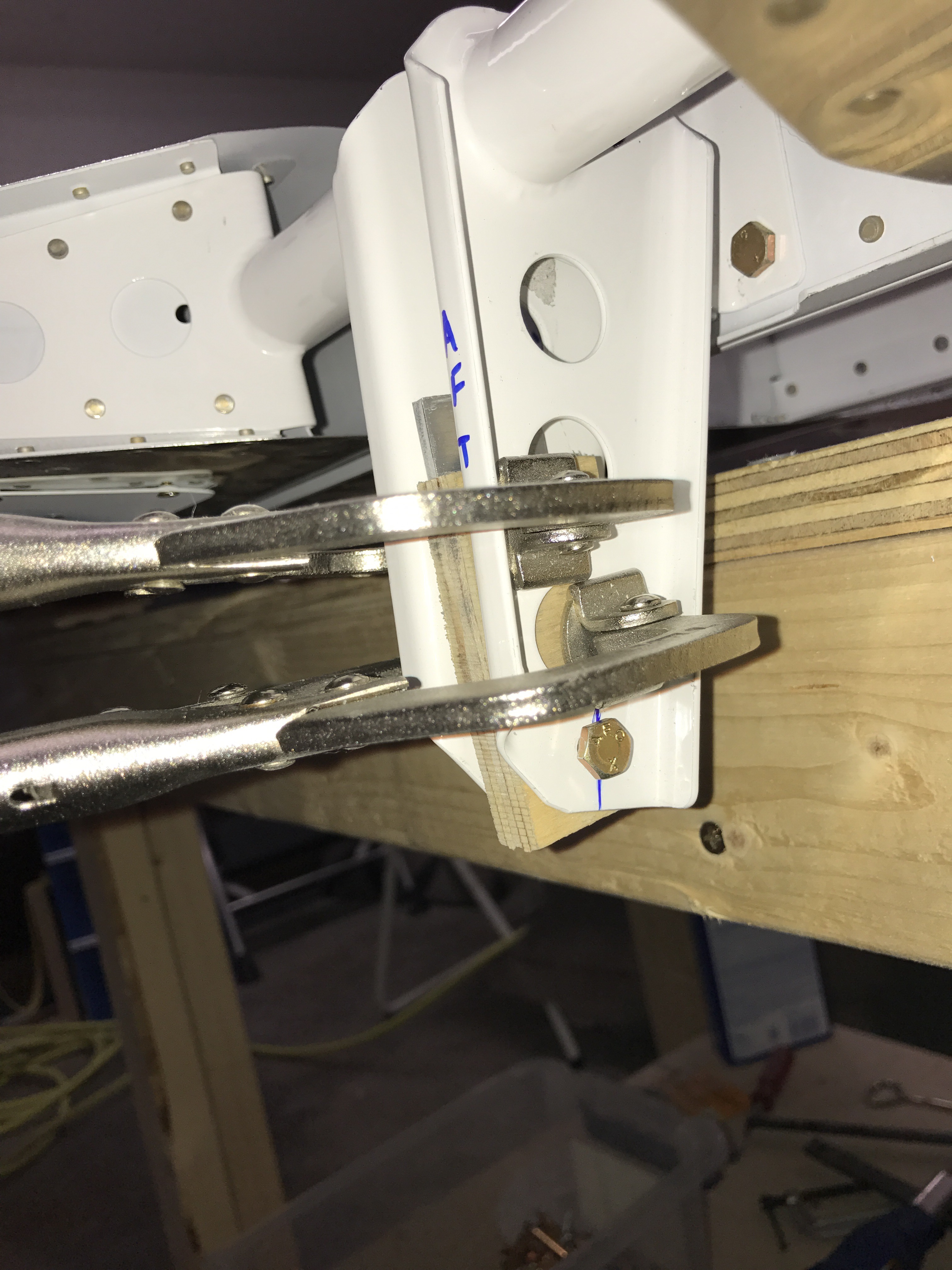
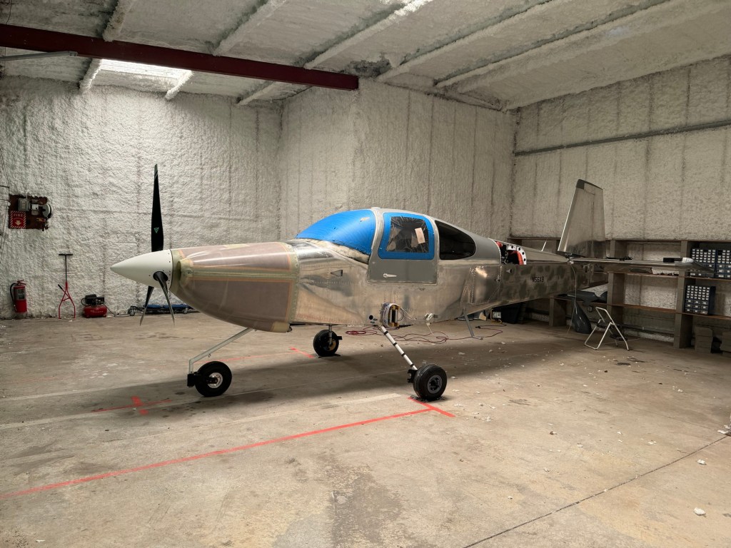
I needed to double check the nose wheel nut break out force and get a cotter pin installed. I really should drill a hole in the floor to thread a ring into for the strap, but I was able to use some blocks I had lying around and my creeper to pull the tail down, lifting the nose wheel off the ground.

I also spent an inordinate amount of time trying to bleed my brakes. In the end, I had to use a garden sprayer type setup to be able to build up enough pressure to push the hydraulic fluid from the brake caliper all the way up to the cylinder on the firewall. All other methods I tried (oil can, and also a vacuum bleeder from the top) failed to be able do the job.
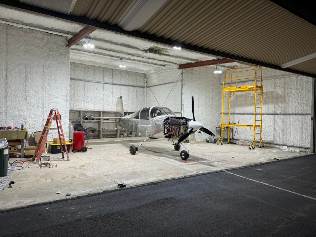
I knew when I got my hangar that the single halogen light was not going to be enough. Still, in order to make progress, I made due with the use of some portable lights in the area(s) I was working. One day the bulb burnt out and rather than replace it, I took it as a sign that I needed to stop and just upgrade the lighting in the hangar. Below is the result of adding some new LED lights.

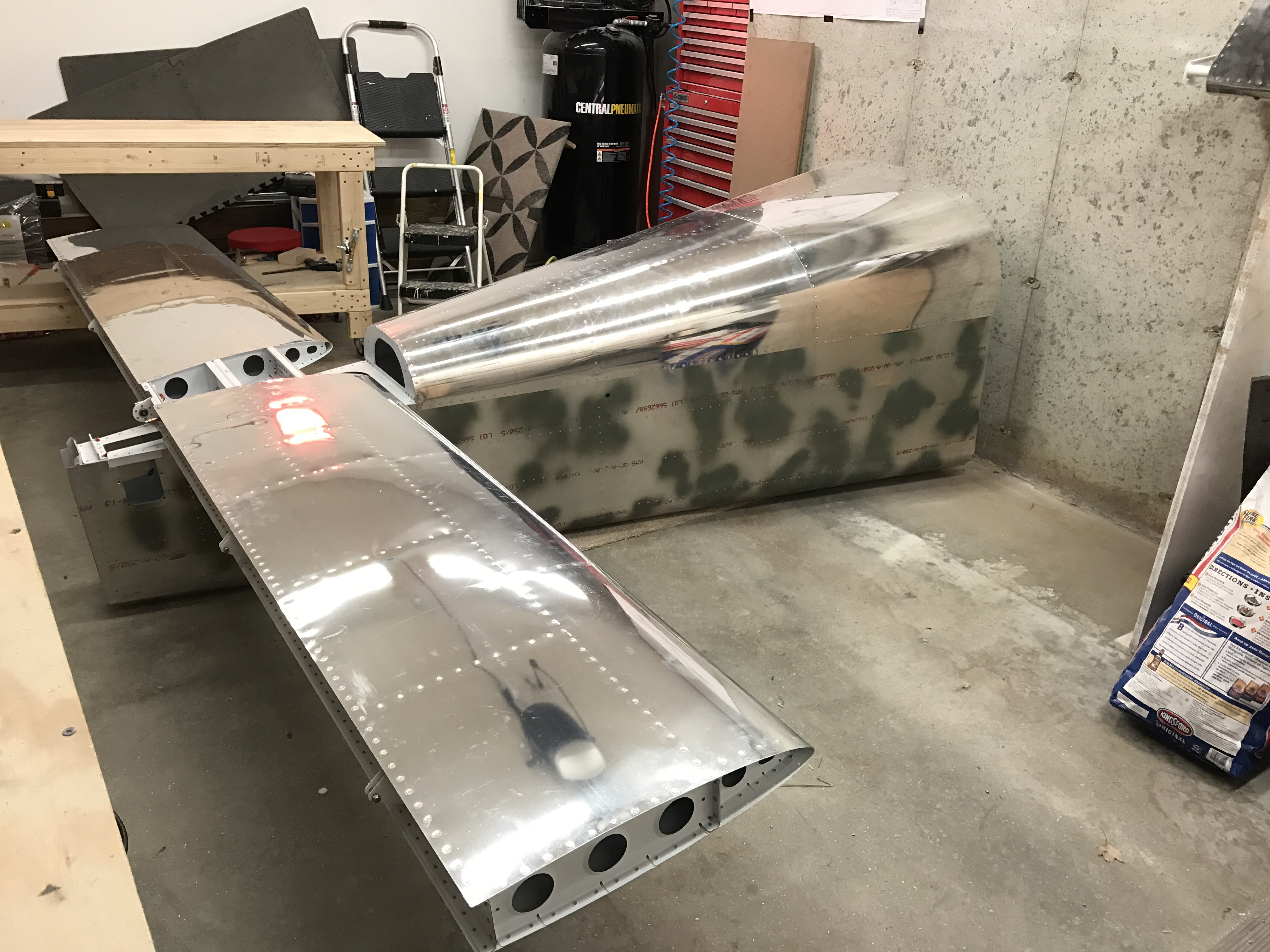
Once my ZipTips were done at home and before the first snow, I was able to get some help to transport the wings to the airport and subsequently get them onto the airplane!!!


Since getting the wings on, I’ve been able to get the flaps and ailerons on and rigged.

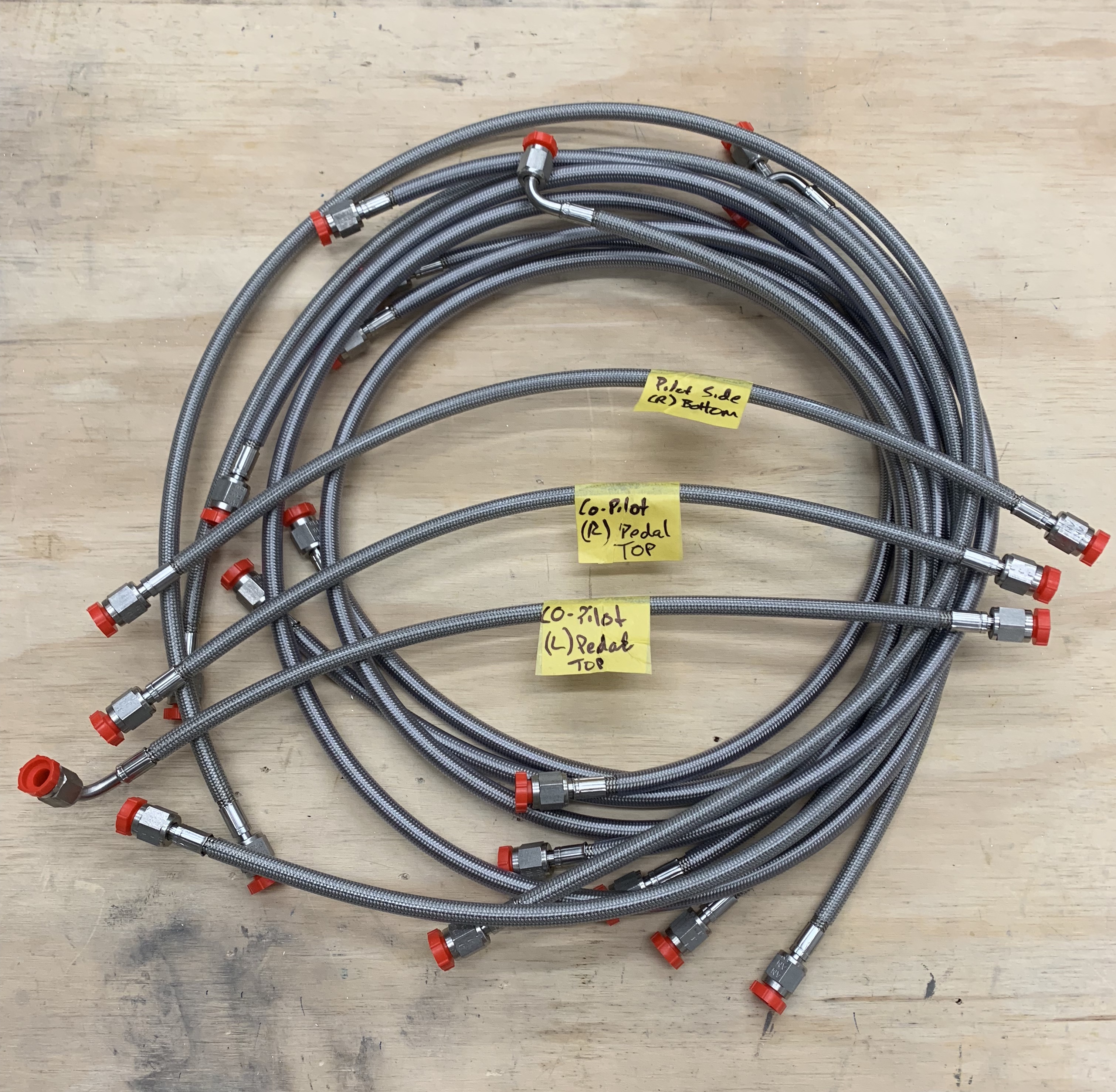
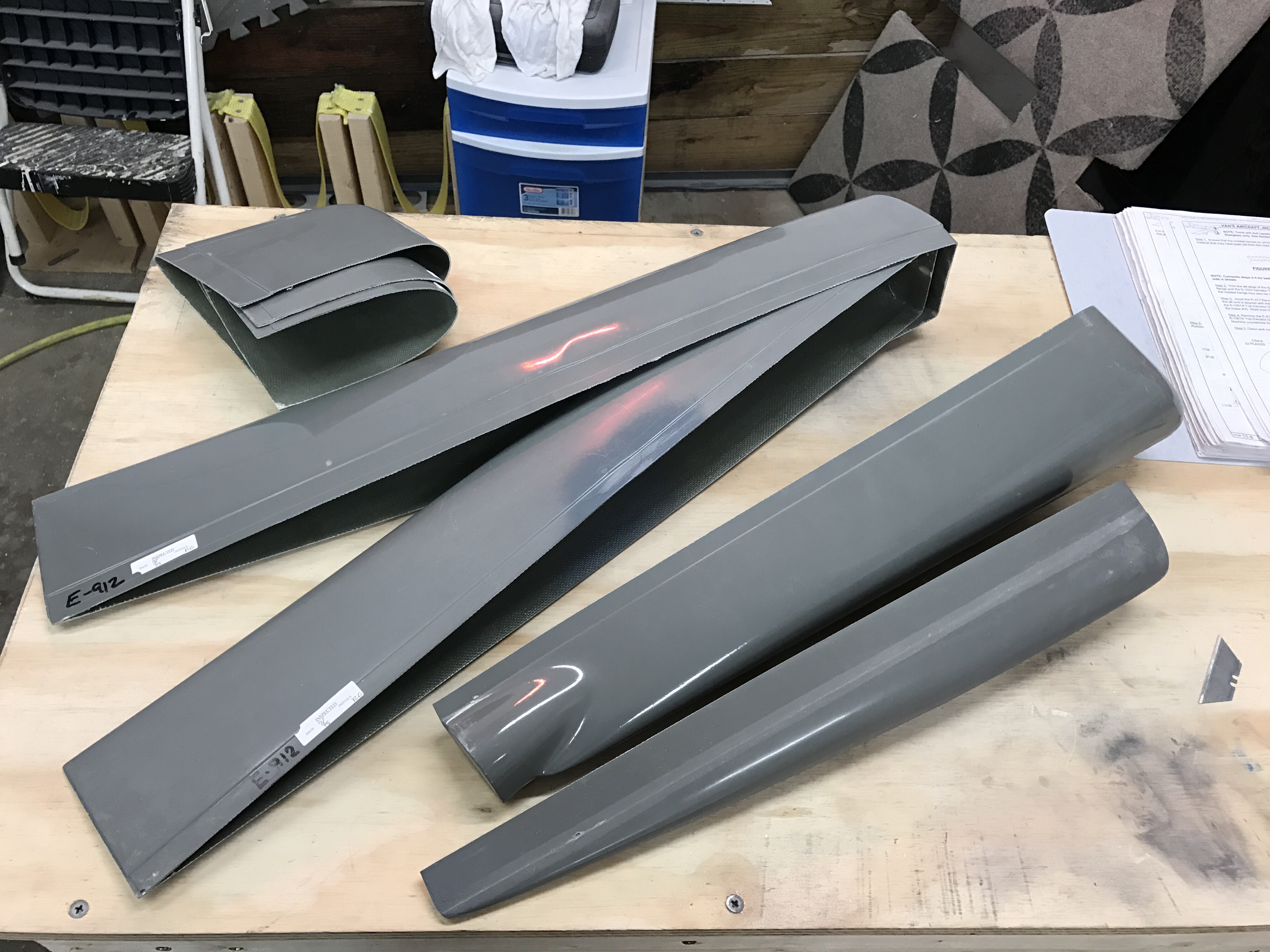
I’m now working on finishing up section 44 which is mostly about wing root fairings, fuel tank vent lines, and connecting the fuel lines between the tanks and the fuselage.


In testament to the user friendliness of avionics these days, Declan seemed to pick up on how to use the EFIS right away. 🙂

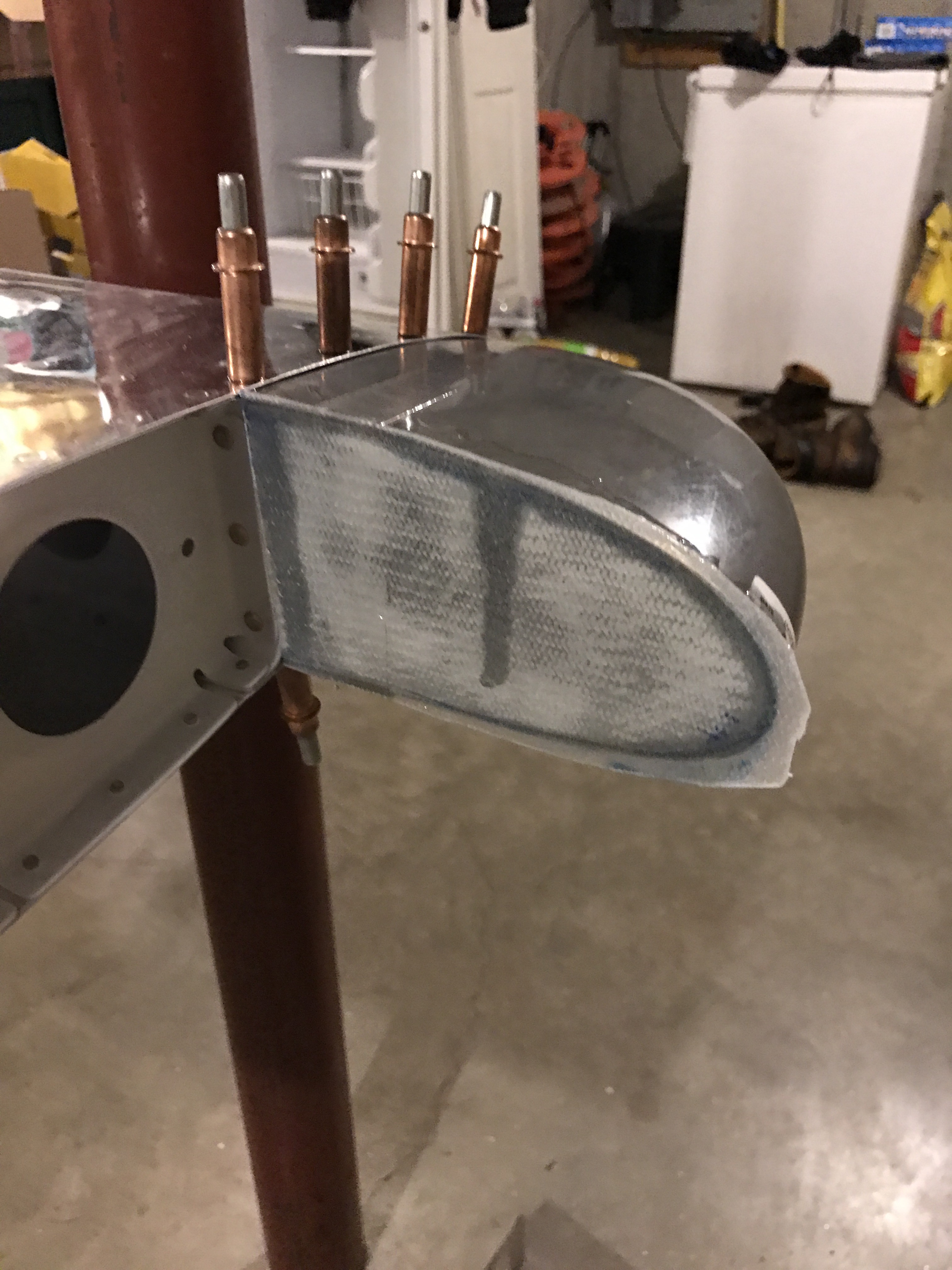
I used some of the soft aluminum tubing to make the vent lines for the tanks as shown below.

So what remains is to finish the wing root fairings and get my fuel lines connected. Then I will need to take the wings off one last time to debur some things and finish some nut plates on the tank. Then I can bolt the wings permanently and finish up the electrical wiring.
After that it is mostly getting ready for first engine start and preparing for inspection.