A bunch of additional work on the AC and O2 Systems. Both of these are nearly complete now. I mounted the remote O2 Fill port in the cross brace near the baggage door for easy access for filling.
Remote fill port with gauge.
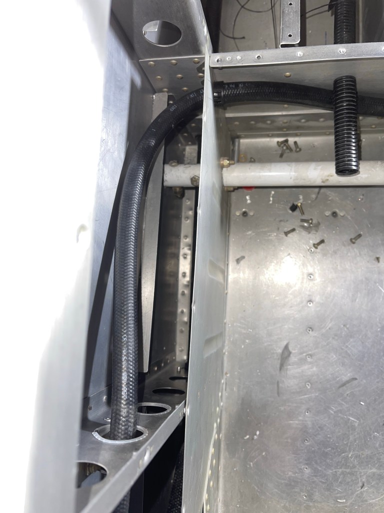
Below you can see the remote O2 regulator mostly plumbed and the line along the side wall going to the remote fill port.
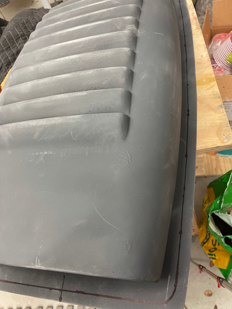
I spent a bunch of time looking at what to do for an air collector to combine air-conditioned air with fresh air coming from the rear NACA vents. I didn’t have a ton of space to work with somewhat due to shifting the evaporator forward for clearance to the top J stiffeners. I eventually settled on expanding the 2″ cut on the left side to an oval 3″ cut to match the fiberglass piece provided by Airflow AC. I kept the 2″ opening on the right to feed fresh air to the overhead.
3″ duct on left for feeding AC to the overhead. 2″ duct on the right for fresh air.
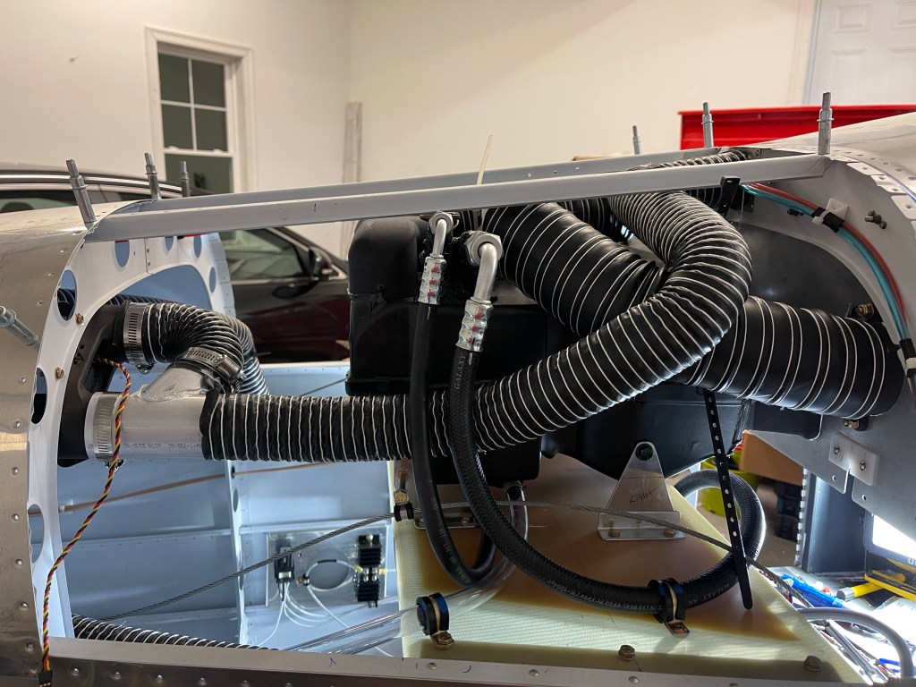
Below are the 99% complete pics of the evaporator and all the associated hoses. I did use an AN3 blot with some tubing as a standoff and an adel clamp near the rear of the shelf to hold the seat belt cable up so it wouldn’t fall downward and rub against the hoses.
Left side.
I ended up using a Y adapter to combine the fresh air from the left and right NACA vents through the Aerosport NACA vent controller to the overhead.
Right sidewith Y adapter shown to combine both left and right fresh air into a single 2″ duct.
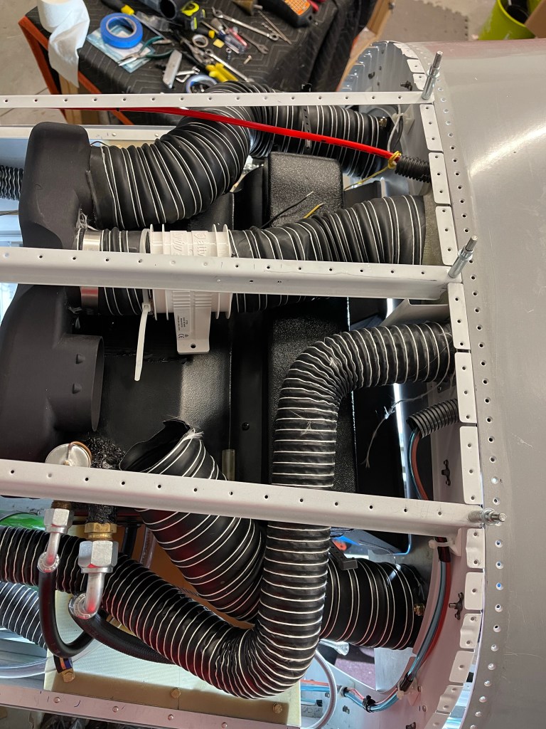
An overhead view. of the routing. I ran a little short of 3″ tube and need to get some more to finish the right side cabin flood connection.
Finally a view from the left side showing the fresh air connections from either side to the NACA vent controller to a single 2″ duct. Here you can also see the evaporator condensation drain in place, but not riveted yet to the belly of the plane.
I decided to send my Mountain High bottle back to take the regulator off of the bottle (shown on the bottle below) so I could remote mount the regulator. That will give me the option to take the tank out and get it filled at a shop somewhere. I chose to copy Joe Keys’ installation and mount the bottle to the right side behind the baggage bulkhead. I used an ELT mount along with some angle and flat 1/8″ stock aluminum bar. The angles were mounted to the J stiffeners and I used one hole of the ELT mount for attaching the mounting brackets. It’s hard to see in the pictures, but I used 1/8″ flat aluminum bar between the bottle mounting bracket and the angle/ELT mount to Secure to extend as far as I needed to and attach to the structure.
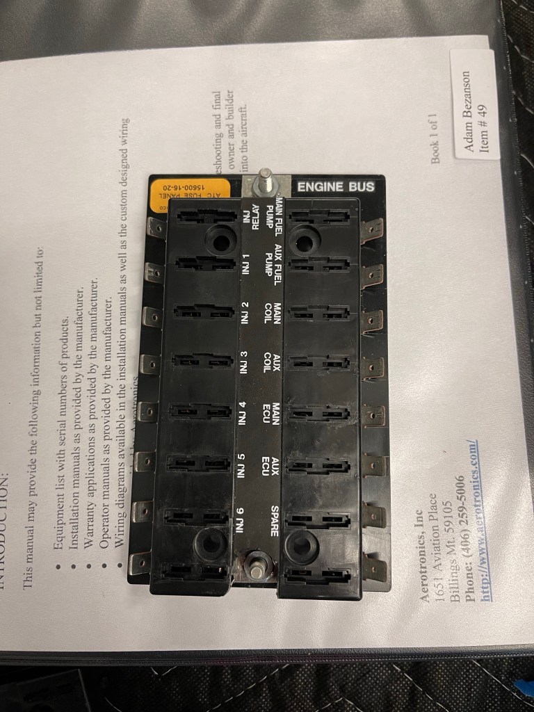
In somewhat of a paranoid redundancy of my engine bus move, I decided to modify the fuse block to add a 2nd stud. The unit has a spot (both a hole and an indent in the plastic) for a 2nd stud.. it’s just not exposed. Below is a picture of the fuse block as it came to me.
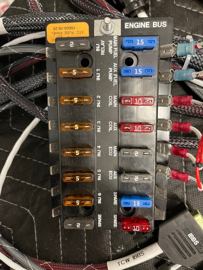
I popped the top open and inserted a second stud and then drilled the plastic to expose the stud and be able to tighten down the nut. This will allow me to have the 2 separate feeds of the engine bus connect to different locations protecting against a nut coming loose or something breaking from removing power from the fuse block.
Fuse block modified for 2 studs.
I then moved on to more AC work. I got the skinnier return ducts from Bill and installed them. This moves the whole evaporator forward to give more clearance to the J stiffeners on the top.
Skinnier return ducts installed.
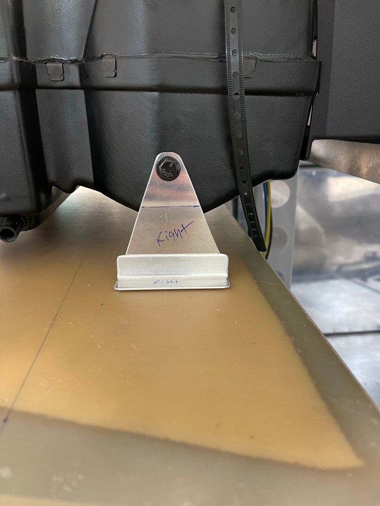
With those installed, I positioned the evaporator, and fabricated new forward brackets with an angle and some scrap metal, seeing it sat much higher than the bracket provided to me and they didn’t reach the shelf. This was a suggestion from Bill.
Fabricating new forward brackets
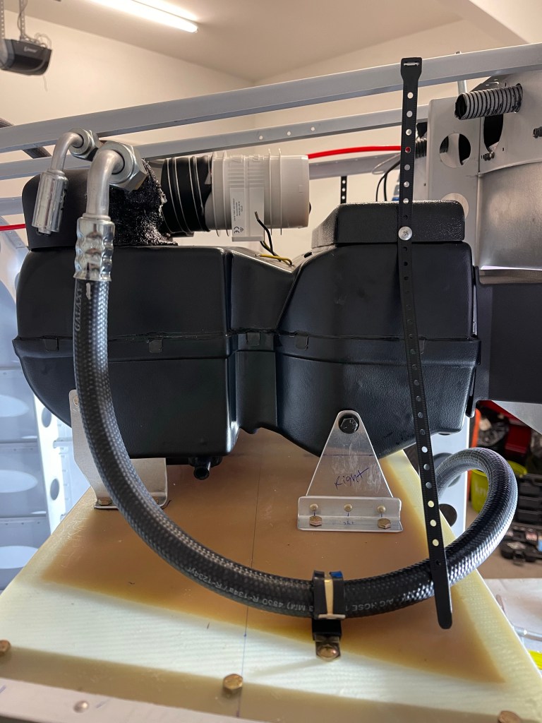
I spent some additional time routing the hoses to the evaporator unit with the service ports easily accessible by taking the lower baggage bulkhead off.
AC hose routing to evaporatorAC hose runs with service ports shown. Hose to the dryer unit.
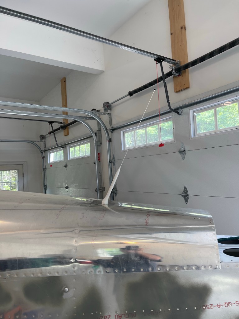
Then it was on to antennas.. More in the category of finishing electrical runs out to the tailcone. One of the things I had yet to finish was mounting the NAV antenna on top of the Vertical Stabilizer. I fabricated a doubler plate and drilled holes in the skins at an angle to accept the cat whiskers.
I sanded down a long wooden dowel to a point in order to insert nutplates up into the VS to hold the antenna puck in place. I’ve also seen people use a rod threaded for the 10-32 nutplate as well, but this worked okay too.
NAV antenna in place.
ELT antenna was next. A lot of builders try to mount this inside under the fiberglass. Some DAR’s, including the one I’m using, want to see this external to the airplane.. so I decided to just bite the bullet and put it just forward of the Vertical Stabilizer. I fabricated a doubler, riveted it to the skin, and mounted the antenna in place.
ELT antenna.
I also utilized another ELT mount on the left side to mount the diode with it’s heatsink and the Battery Bus relay. Shown just below and aft of the ELT.
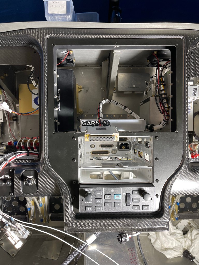
Then it was lots of panel wiring. I first got the remote transponder mounted on the left side with some angles added front to back.
Remote Transponder mounted.
I mounted all the needed components not already on the avionics shelves to the sub panel shown below.
Subpanel components mounted.
I then put the metal panel frame and outer panel back in place and got the wiring harness re-attached to all the switches etc..
Panel wiring stats now!
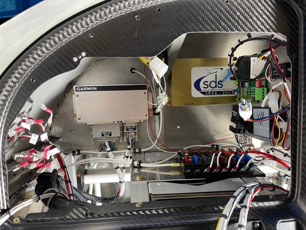
A bunch of time was spent locating the fuse blocks and getting the basic power connections hooked up. Still lots to do, but this is a snapshot of where I am today. Left side, right side, and center of the panel.
Pilots side. Engine bus fuse block is here… mounted on top of the transponder.Co-pilots side. Fuse blocks were the bulk of the work so far on this side. Center part of panel. Not much going on here.. I did wire up my defrost fans..
My panel items don’t contact the sub panel, but the connectors with wire bundles did, so I cut out a rectangle from the sub panel to make sure there was plenty room for the connectors and wiring bundles with strain relief.
Cutting a relief in sub panel
I fabricated a doubler per Van’s plans
Sub panel doubler
Laid out a hole pattern, drilled, and riveted it in place.
Hole pattern drilledDoubler riveted in place
I may end up re-connecting the bottom flanges back together once the location of the connectors are in place. I then fabricated supports of the avionics trays and shelf that houses some components to the sub panel for overall support. I used a small angle riveted to the sub panel and connected another angle to it with a couple of rivets. The aft side where it connects to the avionics trays has a screw with a Nutplates for easy removal if ever needed in the future.
I also took some time to fabricate some hinged access doors to get to the AC connections under the rear seats in the first bay. These will secure down using the 2 existing screw locations on the rib. These connections are for the AC condenser.
Access door in rear seat panA view of the access to the AC connection on bottom skin
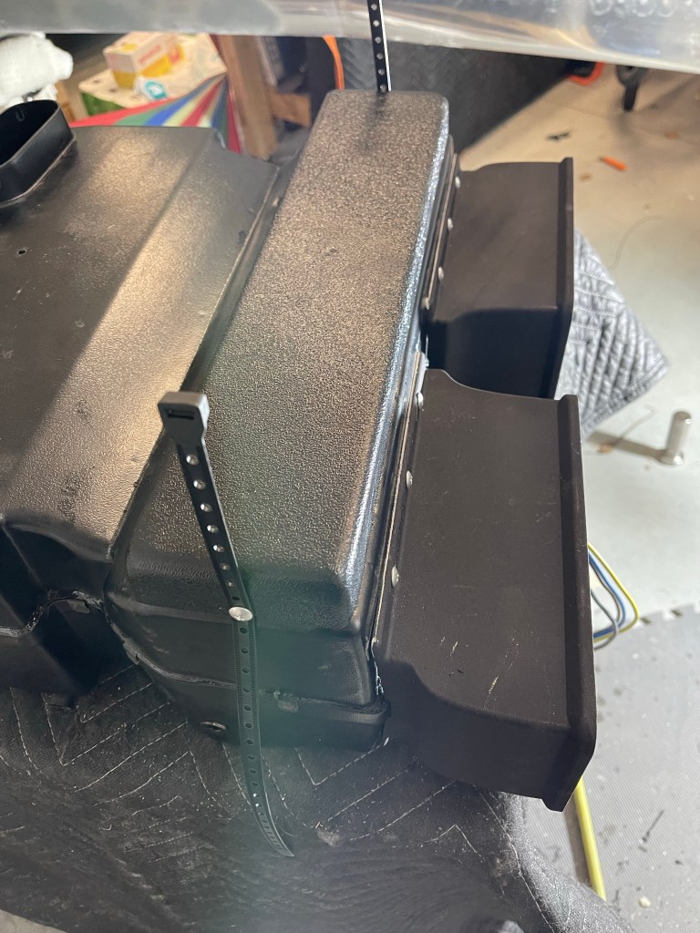
Additional work was started on the AC evaporator unit. First up was to mount the return air ducts.
Right return ductBoth ducts on and interior holes cutCap put on
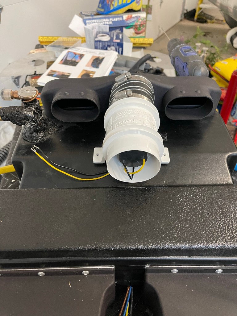
I’m adding a 3″ blower fan to boost airflow into the overhead.
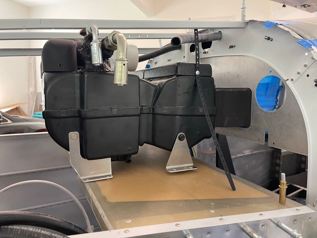
I then placed the flat upper panel from Airflow into position and started rough fitting the evaporator in place on the shelf.
You can see that I will need spacers on the front mounts. I’ve seen several others have to do the same thing. Also I ran into a clearance issue with the J stiffener on the top as shown below. Bill from Airflow said he’s had others run into the same thing due to variation in the units from his suppliers. He’s sending me shorter return ducts to move the unit 2″ forward to solve the clearance issue.
Clearance issue with expansion valveManifold is very close as well, but some gap is present
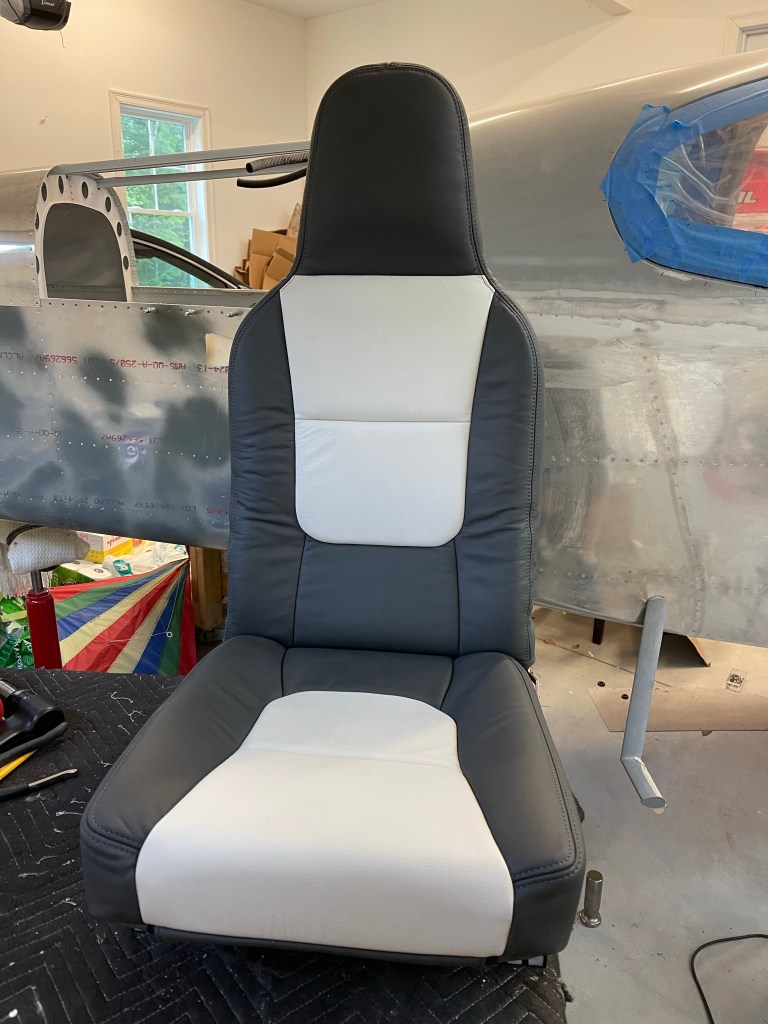
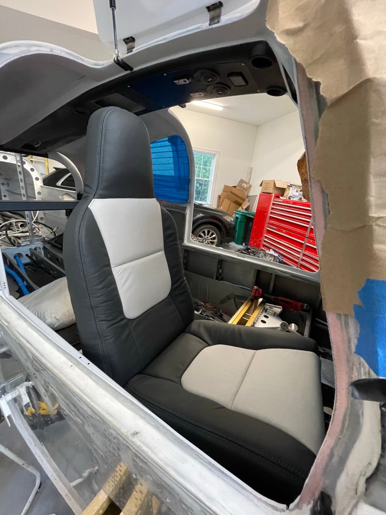
Just before Oshkosh, my seats from Aerosport Products arrived. They came out great! I had to place one into the plane in rough position to see what they look like.
While waiting for AC parts to arrive and needing to finish up some things in the rear of the plane prior to putting the evaporator in place more permanently, I decided I needed to finish some remaining tasks out in the tailcone.
I installed my ELT unit and wired things up to the panel.
ELT in place
I also worked on plumbing my static line from rear to front. This thing needs to go multiple places, so I’ll likely be using a manifold style connector behind the panel vs a long daisy chain.
Static port routing out back.
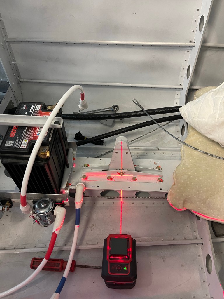
Pitch and Yaw servo installation was next. I used a laser level to help drill the hole needed for the pitch trim arm to connect to.
Prep for drilling pitch trim holein bell crank
Crawling into a small and uncomfortable space is always painful. Here I am in the back sort of on my side to drill out 4 rivets so I can attach the yaw bracket to the airframe.. Wish I had waited to buck these 4 rivets, but got them drilled out.
Fun in the tailcone. Pitch and Yaw servo brackets in placePitch and Yaw servos in place
I finished up the routing of the AC hoses down the right side of the fuselage. The hose going all the way to the tailcone dives down towards the floor and goes through the bottom most lightning hole to make sure it doesn’t interfere with the flap tube in the next bay aft. I placed a small piece of angle on the angle attached to the side skin, used nut plates to screw the 2 angles together and then utilized a nut plate to keep the hose from rubbing on the angle attached to the skin.
View of the metal piece riveted in all 4 corners of the lowest lighting hole with a bushing through the center for the hose to pass through.
The hose destined for the condenser scoop, goes across the flap tube area on it’s way across the tunnel and to the 1st bay under the left-most rear seat.
Hose continuing to the tailcone under the right rear seat.
I utilized Adel clamps anchored to the step to route the hose inward and keep it away from the bolt holding the step in place. It then makes its way aft to the tailcone.
Similar for the hose going from the condenser to the tailcone.
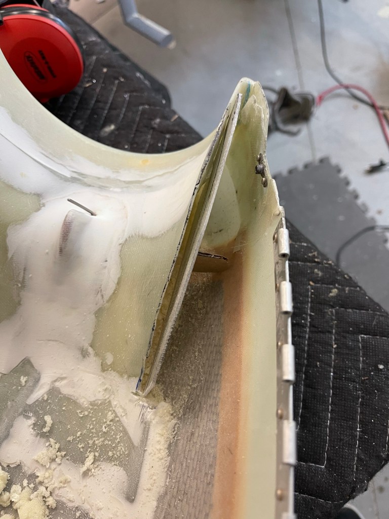
With the hoses done short of crimping on the ends, I started working on the evaporator shelf by using cardboard as a template.
I test fit the cardboard until it was trimmed correctly to sit between the longerons.
I then used the cardboard to mark up the fiberglass shelf and trimmed it, sanding a little bit to get a good fit. Shown here as well are the 3 holes matched drilled into the shelf brackets that get riveted to the longerons.
One other small task was to trim the upper cowl ramps and add a “wall” so that the baffle material could sit in-between the upper air ramp and this “wall” so it has something to push against.
Using some scrap fiberglass to trim up a “wall”
I then mixed up some flox and bonded the “wall” in place with a small “D” shaped piece to provide support against the cowl wall. This was repeated for the other side.
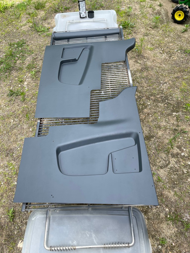
One nice day, I decided to head outside and paint the interior panels. I ordered the lighter tan ones knowing that I was going to paint them a darker color. I think they came out nice!
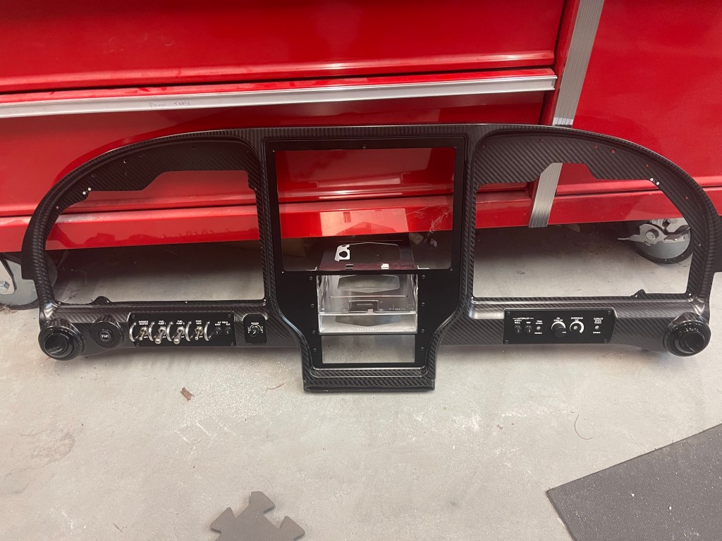
I ran into a snag with continuing with the evaporator install so I worked on completing disassembling the panel. I removed the wiring harness and separated the metal sub frame of the panel from the carbon fiber.
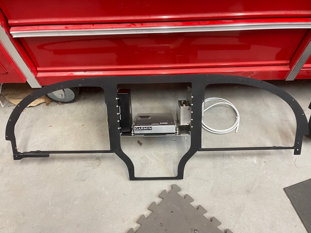
Wiring Harness removedCarbon fiber panelwith avionics trays. Metal subframe with shelf for various components.
I spent some time getting the metal subframe in place, followed by the carbon fiber panel with the avionics trays. This first test fit was mostly done to mark the sub panel where I’ll need to cut away and reinforce making room for the connectors on the back of the 650 etc.. Not a whole lot needs to be removed just a small rectangle near the bottom and really just for the connectors and so the wiring harness doesn’t get bent too much.
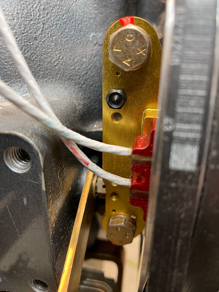
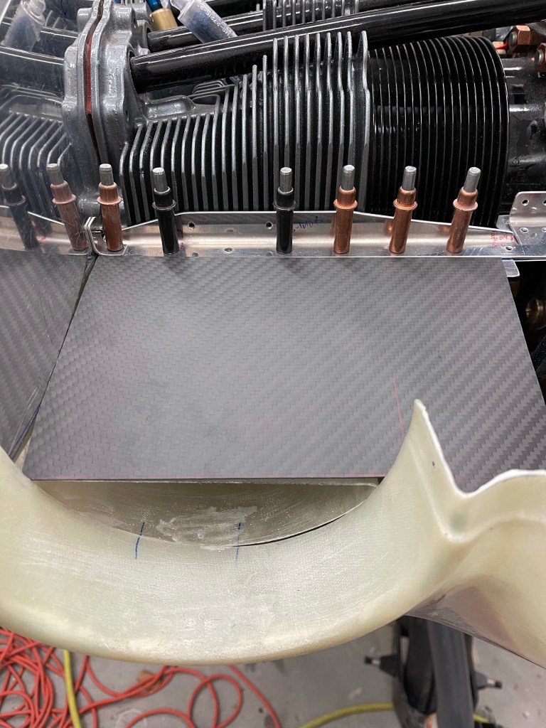
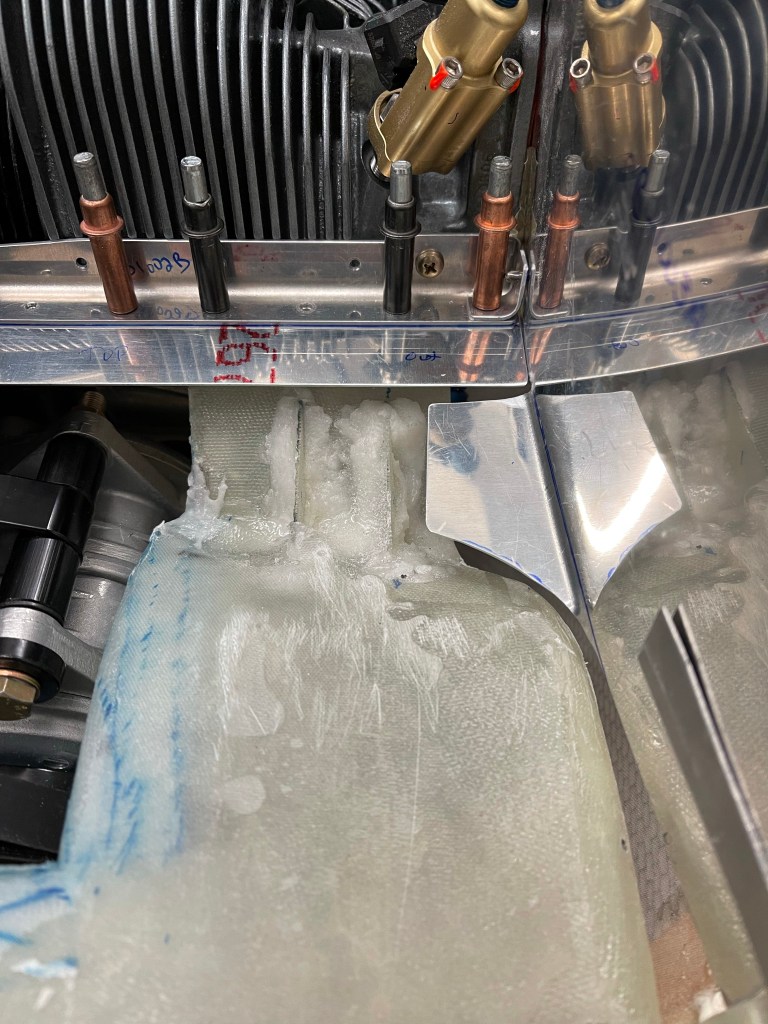
I’m probably being a little paranoid here, but I’ve decided to protect the wires coming out of the hall sensors up near the flywheel. These connections are needed to keep the engine running. I fear an alternator belt snapping and whipping around as it’s sort of hung up in the area for awhile cutting the wires. Of course, it would have to cut both wires for it to be a real issue, thus maybe I shouldn’t worry about this too much.. However, the solution really didn’t take too much time to implement. I bent up some 0.032″ metal to wrap around the sensor as shown below. One side has a narrower flange to accommodate the alternator tensioning arm.
Metal cageTest fit.
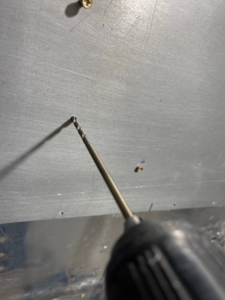
Below you can see the hall sensor and the use of these small center locating punches that screw into a hole and mark the exact location to drill for the bolt.
Punch screwed into position.
Previously I had used this technique to locate the 2 holes for the SDS fuel pressure regulator on the firewall and forgot to write about it previously. I used a piece of scrap metal to drill and use as a template to drill the firewall.
Punches in place
I placed the unit down on the scrap metal and tapped it with a rubber mallet to mark the location location of the holes that needed to be drilled.
You can see the punch marks on the scrap metal ready to drill.
This technique worked perfectly and allowed me to drill holes for the regulator on the firewall that exactly matched the hole location on the regulator.
Back to the metal guard for the hall sensor… I punched the top side, drilled the hole, and once that hole was located, I installed the bolt and marked the location of the 2nd hole then drilled that and bolted it to the hall sensor mount. Below is a test fit of both bolts installed.
I re-used some aluminum fuel line to route the wires from the hall sensors through. I used an Adel clamp to secure it with the one of the bolts. drilled a hole through the baffle and installed a piece of angle on the aft part of the baffle for another adel clamp.
Front part of the tubing with adel clamp. Aft part of the baffle with angle and adel clamp.
Below is the whole thing put together. Obviously the wires will ultimately be routed through the tube, but I need to remove the baffle and paint it at some point, so waiting to do that until after that is completed.
Also the DB-9 connectors on the end of the hall sensor wires are soldered on.. so another reason to delay putting them through the tube just yet.
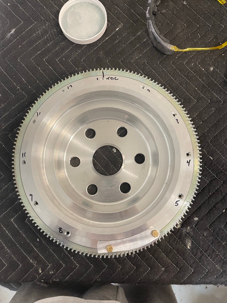
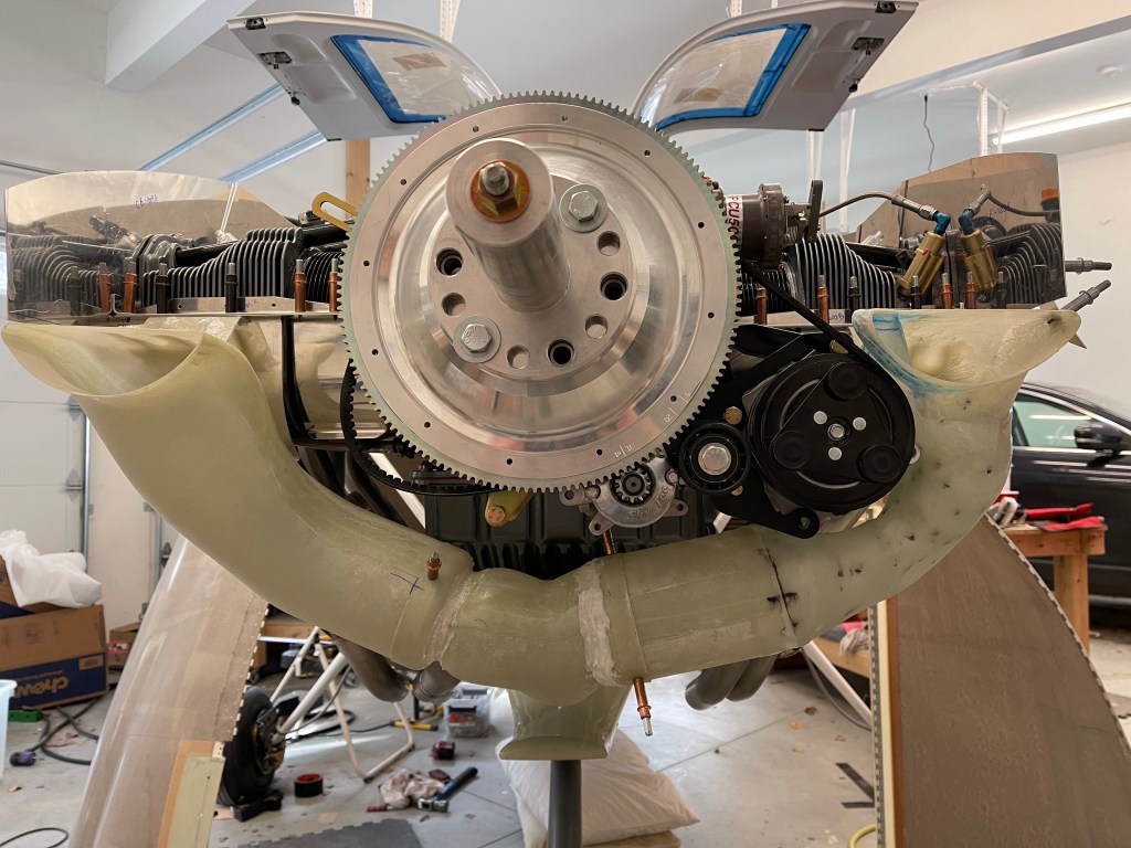
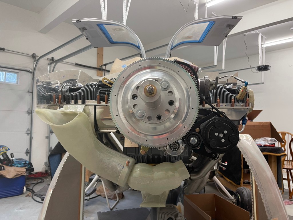
My engine builder supplied a flywheel with the magnets for the SDS system already installed, but I needed to install the magnets in the dual pulley flywheel suppled by Airflow AC. I basically followed this blog linked on the SDS website. https://tasrv10.com/?p=2822.
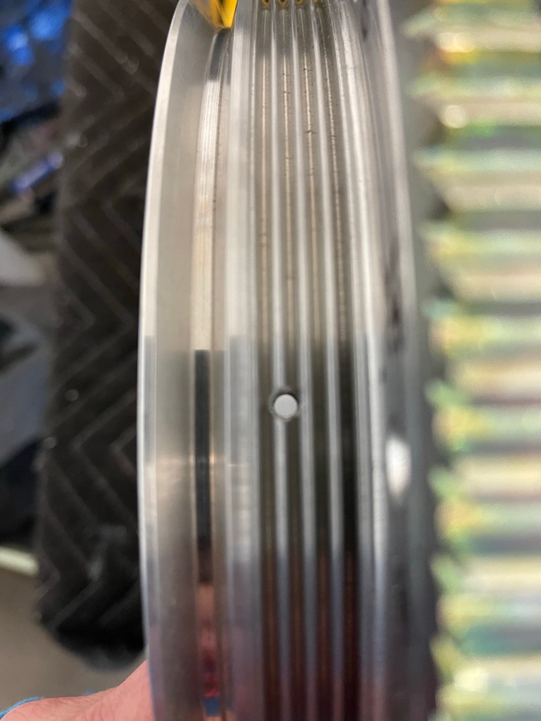
Below is drilling the holes with the drill guide provided by Ross.
I wasn’t quite as lucky as the linked blog post and the hole sort of ate into part of the grove, but not completely.
Drill hole location.
I mixed up some 5 minute epoxy, as specified, and also applied red loctite onto one of the grub screws, which was inserted into the hole from the outside. The magnet was inserted into the hole from the outside. The grub screw was screwed down until the magnet was basically flush with the inner surface of the flywheel.
Magnet flush with the inside
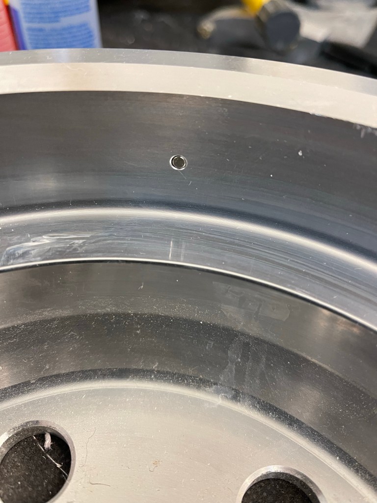
Once everything cured.. I decided to buy the Devcon Titanium putty recommended in the in the linked blog. It is expensive and you really need a very small amount compared to what is provided, but I didn’t want to skimp on this. I prepped the flywheel and applied the putty to each hole location as shown below.
Putty applied to one of the holes.
I let the putty cure for approx. 3 hours and then sanded it using a combo of files and sandpaper. It was a bunch of work, but the end result is what is shown below.
End result of the putty sanding
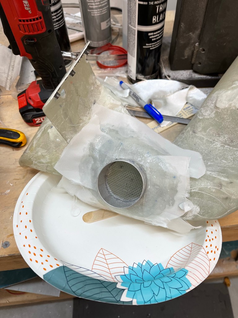
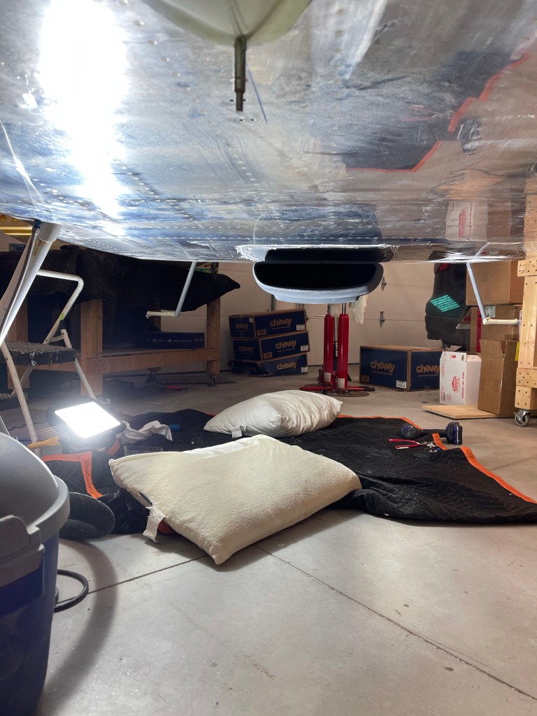
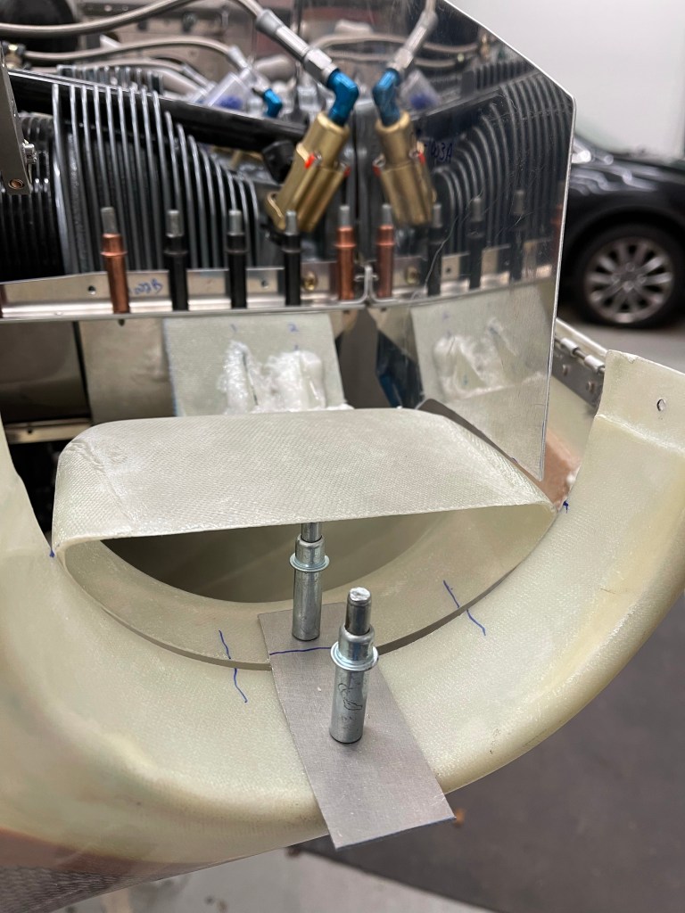
One other thing left was to size up the air intake into the left size heat muff. I mocked this up with some skeet tubing I has lying around. It seemed like it would work, stealing some air from the left side intake,.
I cut a 2″ hole in the left snorkel.
2″ Hole cut
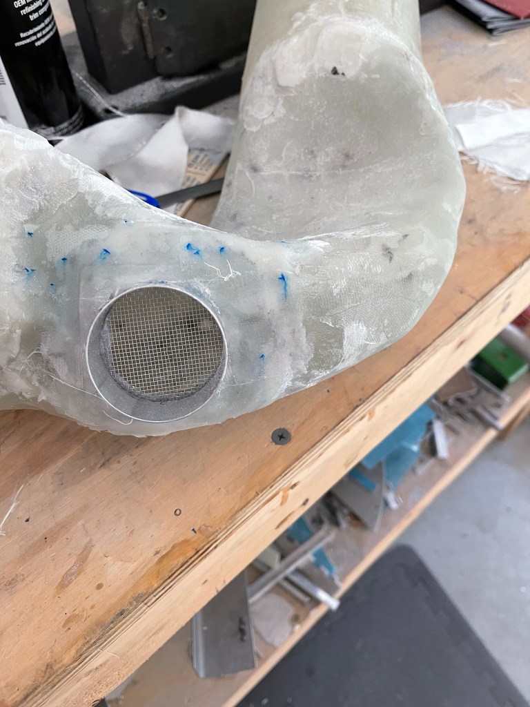
I took a 2″ duct and flox’ed it in place over the hole that was drilled. Once cured, I re-test fit the skeet tube to the exhaust.
Test fit of the heat tube.
I then laid up some fiberglass cloth and some peel ply to glass over the flanges of the 2″ metal tube.
FiberglassCoth and peel ply curing. Finished product.
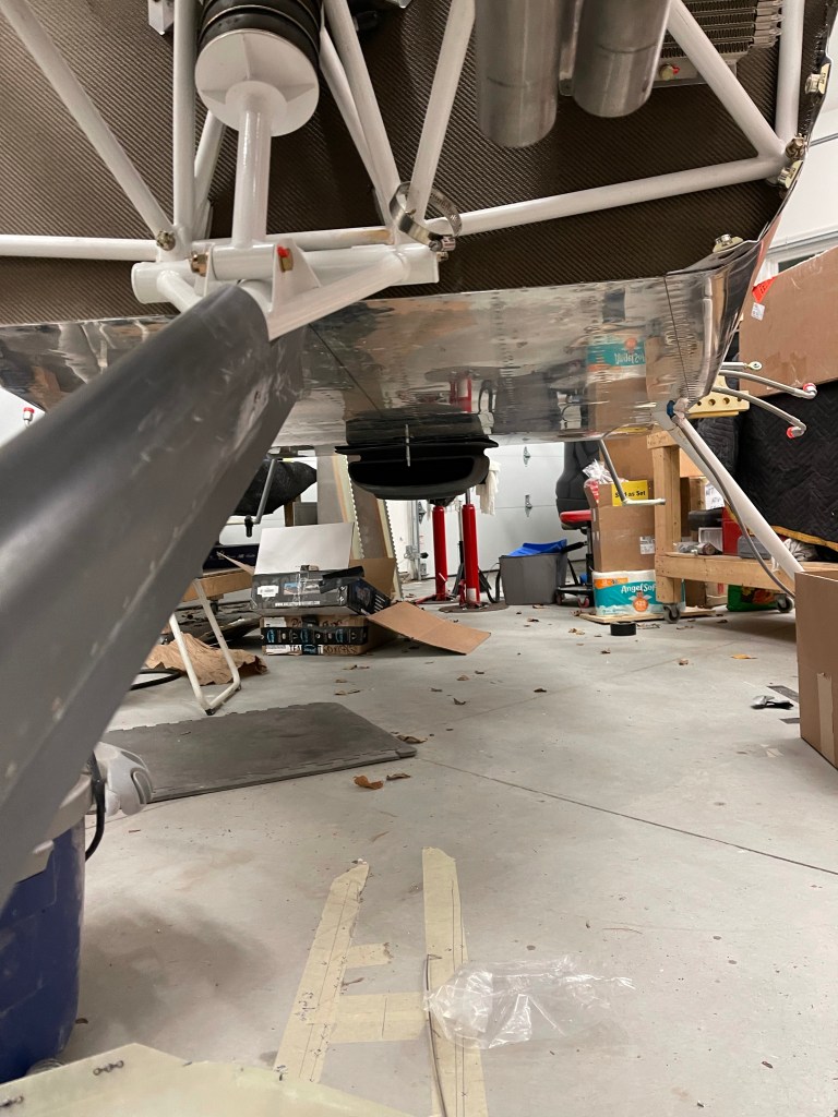
I was then able to get back to finishing up the condenser install of the Air conditioning. I utilized some scrap metal along with some construction paper to mark out the center lines of the connections on the aft side of the unit. I did decide to use some straight connectors that Airflow systems provided to put the connections in the first bay from the tunnel.
Marking the center lines of the aft connections.
I used some cardboard to enlarge the holes and make sure the holes were in the right position prior to drilling into the bottom fuselage. Everything seemed to be correct.
Cardboard template
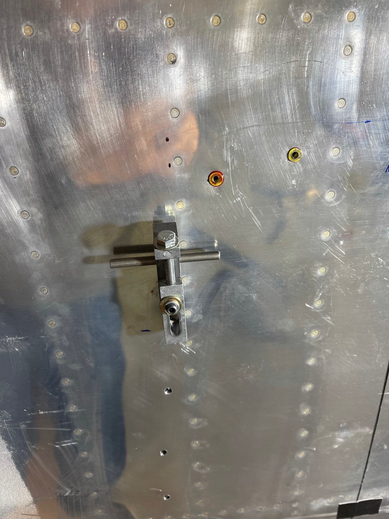
I then took the metal template and screwed it into position and prepared to drill the holes to mark out where the hoses are to be placed.
Metal template in position. Drilling the hole .Both holes drilled to final size.
Then I screwed the AC scoop into position and test fit the aft hoses that go up into the fuselage. Everything worked out well as shown below.
Holes drilled and connections inside in place.
I installed some grommets into the holes to seal them as much as possible.
Grommets in place
A view from the inside with the connections coming up through the fuselage skins.
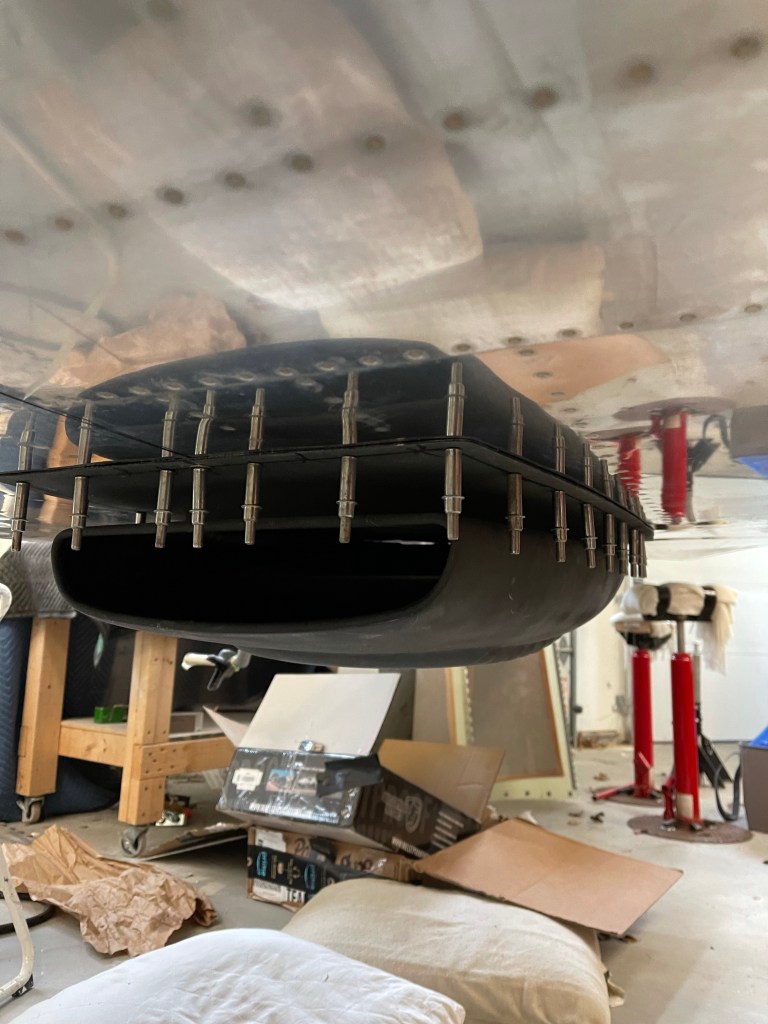
During various periods of downtime waiting for epoxy to cure or waiting on parts to come in.. I continued some work on the Air Conditioning Scoop that houses the Condenser on the belly. The first step was to mark the center line front and back as well as a line around the perimeter for the screw holes to line up to.
I then placed a string between the center point at the firewall and the center point at the tail to line up the centerlines marked on the scoop. A single hole was drilled for a cleco to hold the scoop in place fore and aft.
Side view
I then drilled approx 32 holes around the perimeter per the instructions making sure to not drill into any underlying structure. The corners are where you have to be really careful as they approach the rivet lines for the ribs.
As most of these holes are blind and there is no access from the inside, I had to install rivnuts to accept #8 screws. I practiced on some scrap that I had prior to doing it for real so I could get a feel for the tool and how rivnuts work in general.
Below you can see the rivnut squeezed down and onto the metal on the inside holding it in place.
I enlarged all of the #40 holes that were drilled to the proper size (#2) for the rivnut installation. The holes on the scoop were countersunk to accept #8 flat head screws with a tinnerman washer.
Below is a picture of me using the tool to set the rivnuts into their holes with a small amount of red loctite on the barrel of the rivnut.
Each rivnut has a “key” feature on the inner face of it to help prevent it from ever rotating. A notch had to be added to each hole to accommodate this feature of the rivnut. An example is shown below. I used a flat file to do this..
Seeing I had previously removed the seat pans and baggage area floors on the right side, I oped to use nut plates instead of rivnuts in this area. Also any holes in the tunnel utilized nut plates as well. Given access, using nut plates will always fare better than rivnuts, which could potentially spin in the future and make it impossible to get the screw loosened or tightened without drilling it out.
One of the thing about the scoop, is it didn’t sit very flush to the bottom of the fuselage skin.. so I applied packing tape to the bottom skin in the area and then applied a generous amount of micro around the flange and screwed the scoop into place to cure and fill in the gaps etc.. between the scoop and the skin.
Once cured, I took the scoop off and sanded around the perimeter of the flange. (shown below prior to sanding.
The next step is to put the condenser coil in place and work on a template to drill holes into the bottom skin for the hose connections inside of the plane.
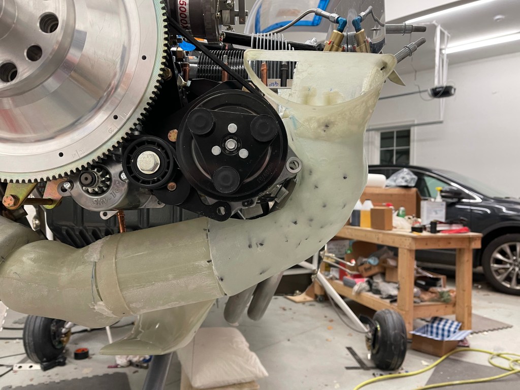
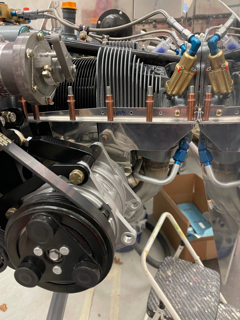
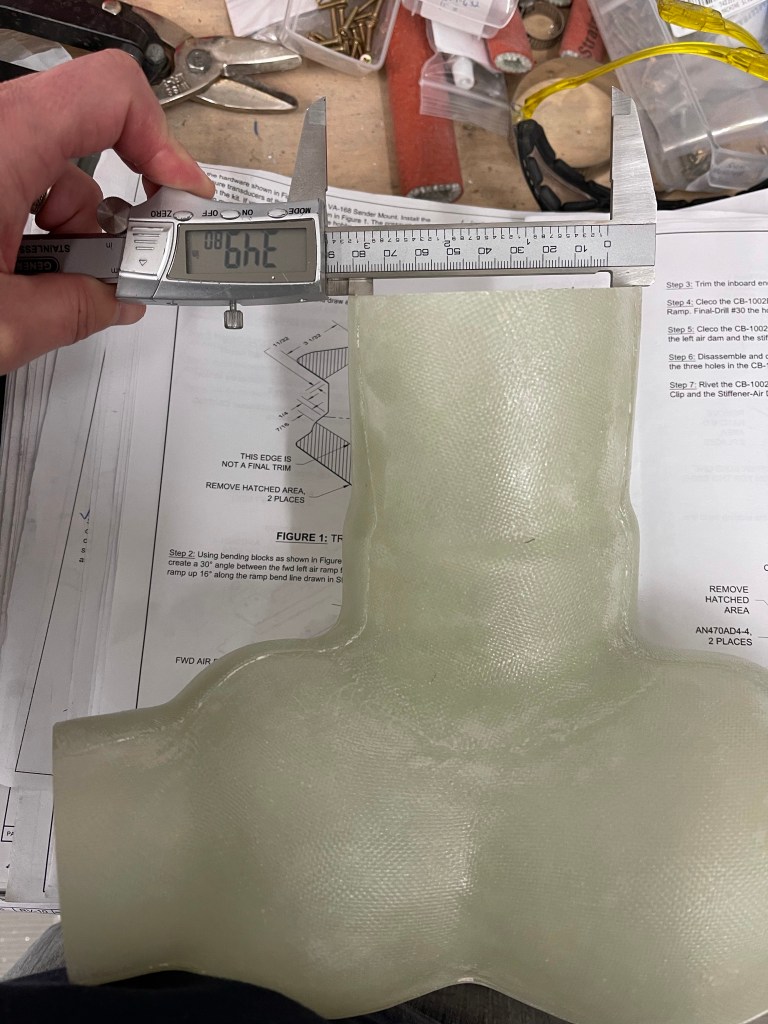
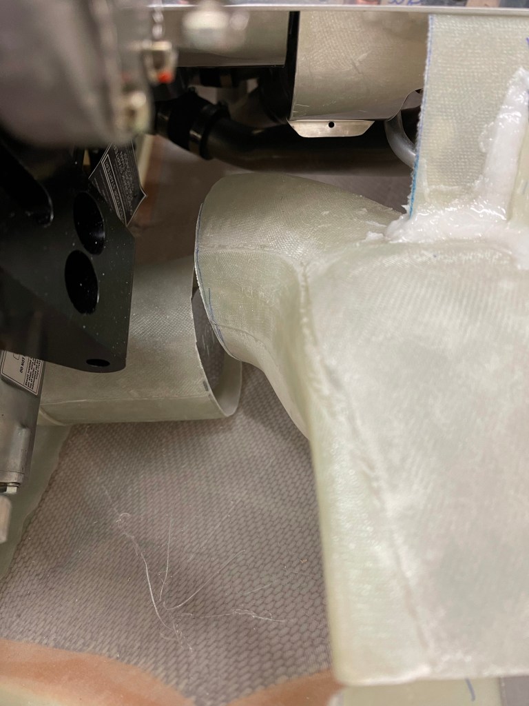
Now that the basic shape of the left intake tube was formed, it was time to sand it down to perfect shape. I used mostly the Permagrit sanding blocks for this task, and it was relatively easy. Of course, at some points I had to put the lower cowl on to make sure I had clearance to it. I also carved out a bit more in the back for the AC hose connections to the compressor.
Foam sanded to shape
I then laid up 4 layers of cloth and put some peel ply over the top and let the tube cure overnight.
Of course prior to doing this I covered the foam in packing tape as a release agent and also sprayed some silicone based release agent on that for good measure.
Once cured, I removed all the foam inside of the tube and test fit it.
I then cut some cloth to close out the top part of the tube where I had cut for clearance to the compressor. 4 layers again were laid up and peel ply placed over the top.
Closing out the top of the tube.
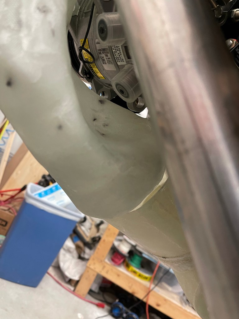
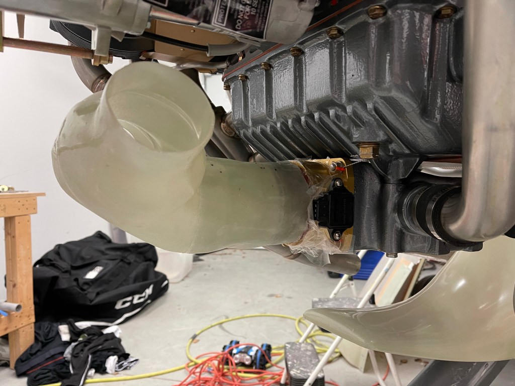
Once cured I test fit the tube once again to make sure things looked good. below you can see the blue sharpie lines that I used to mark the cloth for cutting pieces to shape.
Tube clearance to compressorAft view of bump in for AC hose connectionsCloser look at the bump-in.
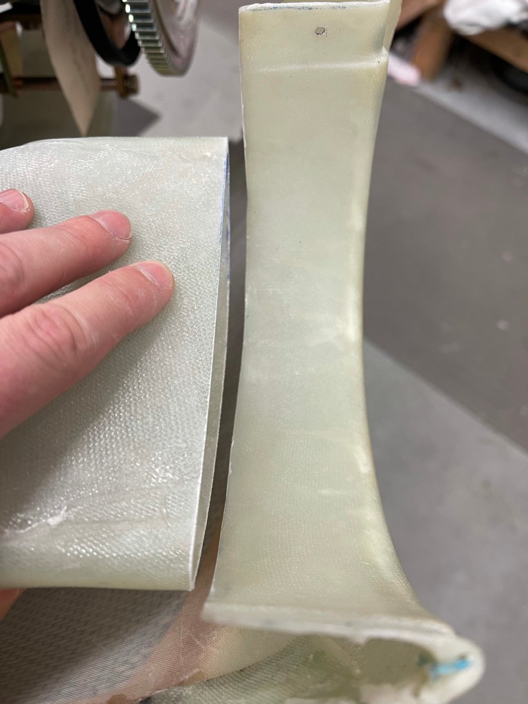
Then it was time to wrap a single piece of cloth to span the gap between the two tubes to join them back together. You can see the black line I marked for alignment. I also used a jack to allow the tube to sit on vs. having gravity pull down on the tube while this was curing. I used a single layer on the outside, because clearance to the cowl is a bit tight. Once this cured, I placed a thick layer of flox on the inside of the tube to fill the gap and create more strength in this area.
re-joining the tubes. Complete except for some sanding.
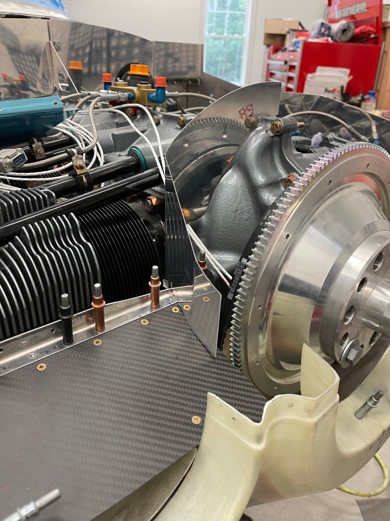
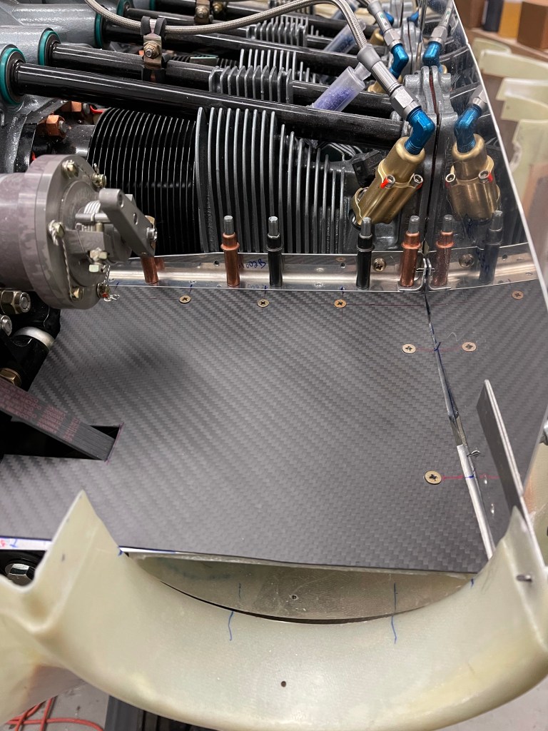
One of the other tasks that needed to be done was to redesign the air ramps seeing I’m using the Showplane’s cowling and the stock metal ramps were cut out for this intake system. I fabricated a .032″ thick piece wide enough to go under the baffle angle and still protrude enough to serve as a flange for the new ramp. This will be bent downward somewhat depending on the angle between this and the from of the intake. It’ll provide a nice flat surface for attaching the ramp material to with screws.
I also bent up some of the side baffle material to provide 1 screw location. I also decided to fabricate up a metal piece that sits up front on top of the intake area. It has a bent flange that will rivet to the side baffle material. I’ve left everything to the inside (closest to the flywheel) long for now. Once I get the center baffles completely figured out this area will be trimmed and I suspect some aluminum angle will be used with some screws to connect the front metal piece to the aft piece I made with screws.
Picture of ramp area prep for screws and carbon fiber ramps.
I then cut some carbon fiber material I bought for the ramps to fit in the ramp area. Again, leaving the inboard side long for now.
Test fit right ramp material
I then match drilled everything, added nut plates, and screws to hold everything down.
Right Ramp.
I put the center baffle material in place after cutting it somewhat. This will need to be angled back towards the intake opening. In fact, I may cut the piece coming out towards the flywheel and rivet in a new piece of my own at an angle to achieve this.
RightCenter baffle piece in place
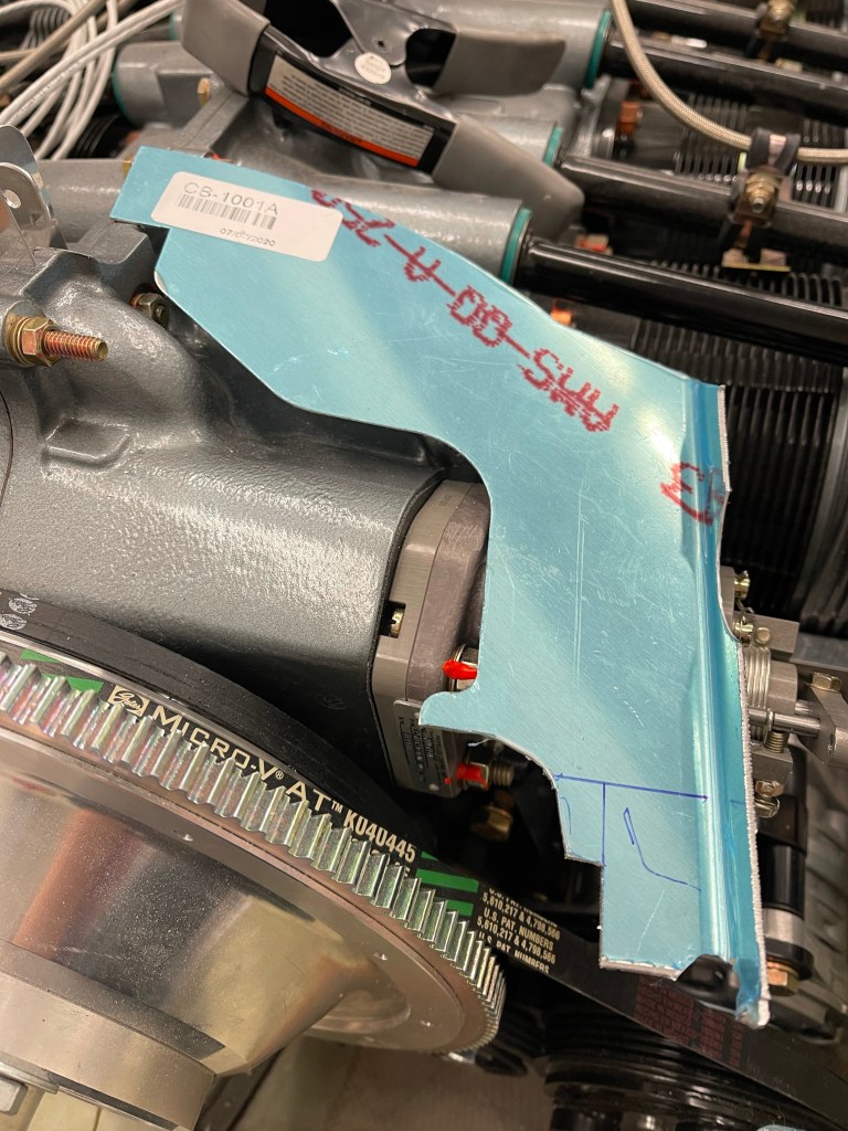
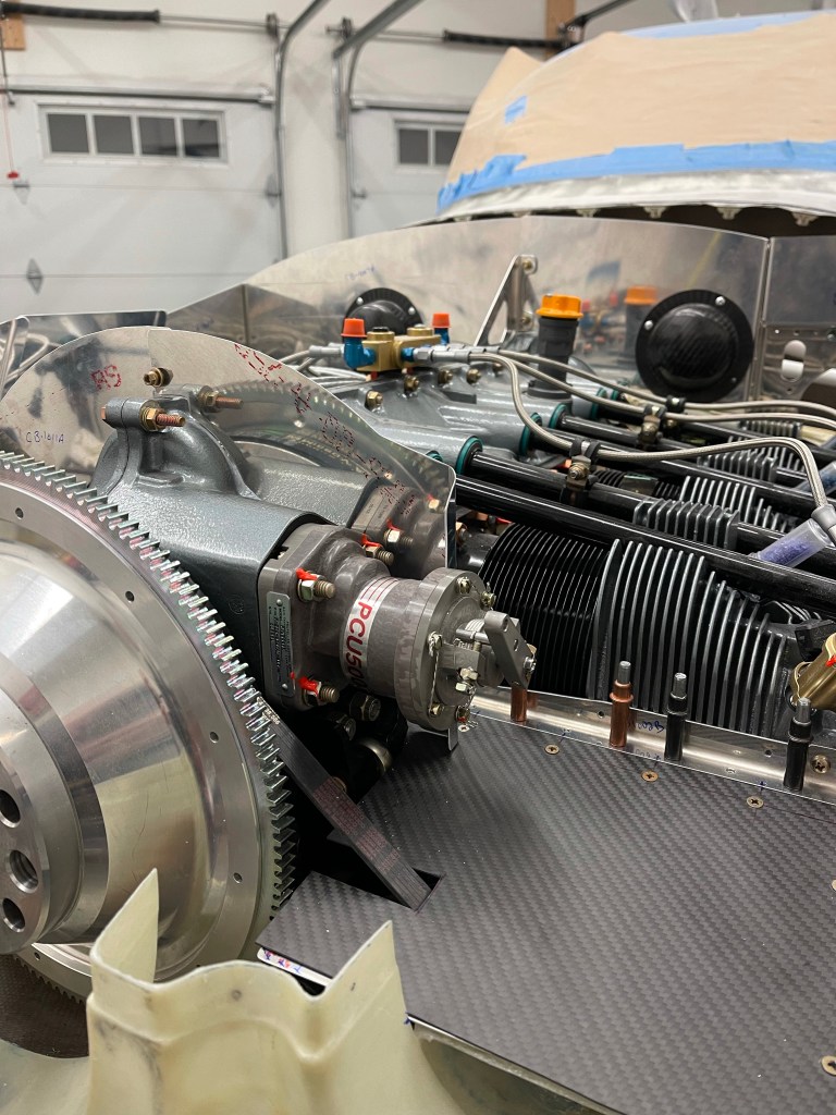
I really had to trim away the left center baffle piece. It interferes with the AC compressor quite a bit. So I decided to cut the forward most section completely off, leaving enough material to rivet more metal to later, and also the notch for the aft part of the prop governor. Later, I’ll work on a custom piece to go over the prop governor and along the ramp to the intake area.
Working on the Left center baffle Match drilling the hole for the 2 center baffles.
The same process was repeated for the left, with the exception that the compressor complicates the ramp..
Metal flange for ramp added
I decided the best way was to use construction paper to create template prior to attempting to cut the carbon fiber piece.
Creating a templateTransferring template to carbon fiber. Ramp cut and in place. Another angleBending up the side baffle for a screw location. Ramp in place!Another view. Looks like a #6 nutplate made it into my #8 bin.. I’ll have to fix that at some point.. All finished up with the left center baffle in place.
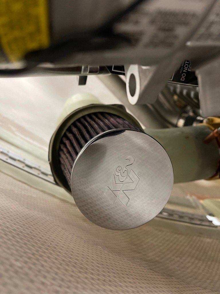
The next area to tackle was the air intake system of the Showplaces cowl. Fiberglass tubes were supplied which take up the bottom 1/4 of each round air inlets on either side of the cowl. These tubes house air filters (one on each side) and join together with a servo plenum. The plenum connects to the SDS throttle body.
These intake tubes cause several deviations including the bottom inlet ramps needing to be completely cut away. I spent some time getting the inlet ramps cut to match the baffle stiffeners on the front of each side of the engine.
Right baffle stiffenerLeft baffle stiffener
I then started to try to get the servo plenum and right intake into position. There are no obstructions like the AC compressor on the right side, so it’ll be the easier side to start with. I did have some trouble getting the plenum onto the SDS throttle body. It’s the correct size (3.5″ ID), but just didn’t want to easily slide on. Bryan at Showplanes suggested cutting 3/4″ slots at the 9 and 3 o’clock position, which is what I did.. That seemed to work better and still gave a nice tight fit.
double checking the ID of the servo plenum.Plenum didn’t want to slide onto throttle body inlet.
Once I got the servo plenum in place, I quickly noted two things
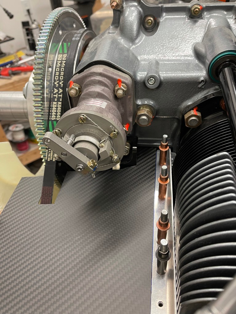
The left side air filter and tube in general is going to have major conflicts with the compressor and the 2 hose connections coming off the bottom of it. This was mostly expected based on builders that have gone before me.
Due to my cowl being shifted forward quite a bit based on my prop/hub combo.. the servo plenum will need to shifted forward as well and an extension made to mate up with the throttle body.
Left side Air Filter will cause issues with A/C compressorNeed to shift the whole thing forward to get the inlet just behind the cowl opening
I wrapped some packing tape all around/over the throttle body and did a layup of 4 layers of glass to create an extension for the servo plenum.
Letting the extension cure overnight.
Once that cured, I worked on properly positioning the right intake tube. This was fairly straightforward and didn’t require any cuts or mods to do so.
Positioning the right intakeRough gap to cowl. A view from below.
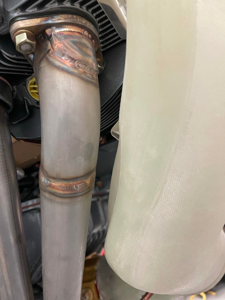
One of the other benefits to my cowl being so far forward, is that the intake tube didn’t need to be modified to clear the #1 exhaust pipe. Below is a picture of the intake tube in place and you can see the stock bump in for clearance. Many other builders had to cut this area out and bump inwards more.
Clearance to #1 exhaust
It was then time to use the provided fiberglass sheet to secure the top part of the intake tube to the baffle stiffeners. I cut a piece wide enough to capture 3 of the holes in the baffle stiffener, enlarged to accept #8 screws. Some triangular pieces were also cut to strengthen the joint as these two pieces are bonded together. I also used a piece of aluminum to hold the intake in place while the flox was curing. Also of note the side baffles needed to be trimmed to match the curve of the intake
Getting ready to bond the two pieces together. Flox on and curing overnight.
The right side was then mostly complete.
Right side mostly done.
I then experimented with some ideas for the left side. Through some reading and asking around.. it seems several builders that have a Showplane’s cowl and AC compressor have chosen to run unfiltered air for the left side seeing there is significant conflict in this area.. I wasn’t too thrilled with this idea.. As once you’re running unfiltered, air will take the path of least resistance and all go through the unfiltered route.. why bother putting in redundant air feeds in this case at all? Although I suppose it would still allow for an alternate air path in the case one side got blocked. I explored some options.. the one I settled on was to adjust the left side to angle the filter downward (more horizontal). Below you can see my attempt at looking at this from a clearance perspective to the AC.. Of course, you also have to balance that against the space you have to the lower cowl..
Filter more horizontal idea.
I marked out lines to basically cut the left side off entirely. I also cut the neck down off as indicated by the right-most lines (well the left-most (bolder) set of the right lines), to allow the filter to re-attach to the stock flange and not have to fabricate something up myself. This is basically cutting 2″ out in the middle and re-attaching the flange back to the plenum.
Marking out the cuts to make to the left side.
What I found was that if I slid the flange part onto the end cap and placed that whole “sub-assembly” onto the servo plenum, it wasn’t too bad of a size mismatch. I taped this up initially to look at clearances prior to floxing the whole thing together.
Filter, flange and end cap taped into place on plenumClearance to AC and hose endsFinally checking clearance to the lower cowl.. There’s plenty!
I took the plunge and cut the servo plenum.. Hey it’s just fiberglass and I can fix it (I suppose) if I mess it up really badly.. 🙂
Floxing it all back together. I’ll eventually sand this down and probably lay a layer or two of cloth over this area.
I then followed the same procedure as the right on the left side (with the compressor removed for now)… I did, however, decide to cut the tube in the middle because of the angle being way off due to my previously described cuts to the plenum.. I chose to insert the tube into the filter end and cut it so that its length is just beyond the filter. Again no need to try to fabricate up a new piece to fit into the end cap when I’ve got a perfectly good piece to do so already.
Aligning and floxing the left sideCut of the tube just at the end of the filter.
I then made some relief cuts to the inlet area around the compressor. Both at the intake area and down the length of the tube.
Relief cut
Looking at the angle of this tube relative to the compressor connections.. it was clear that not even this cut will work and cutting more will just cause a very thin tube.
Another angle of the initial relief cut.
It was at this point that I decided it was probably best to just fabricate a new tube between the intake piece and the filter piece. I cut the intake piece up a little closer up at the widest part of the tube.
Cut off the intake piece
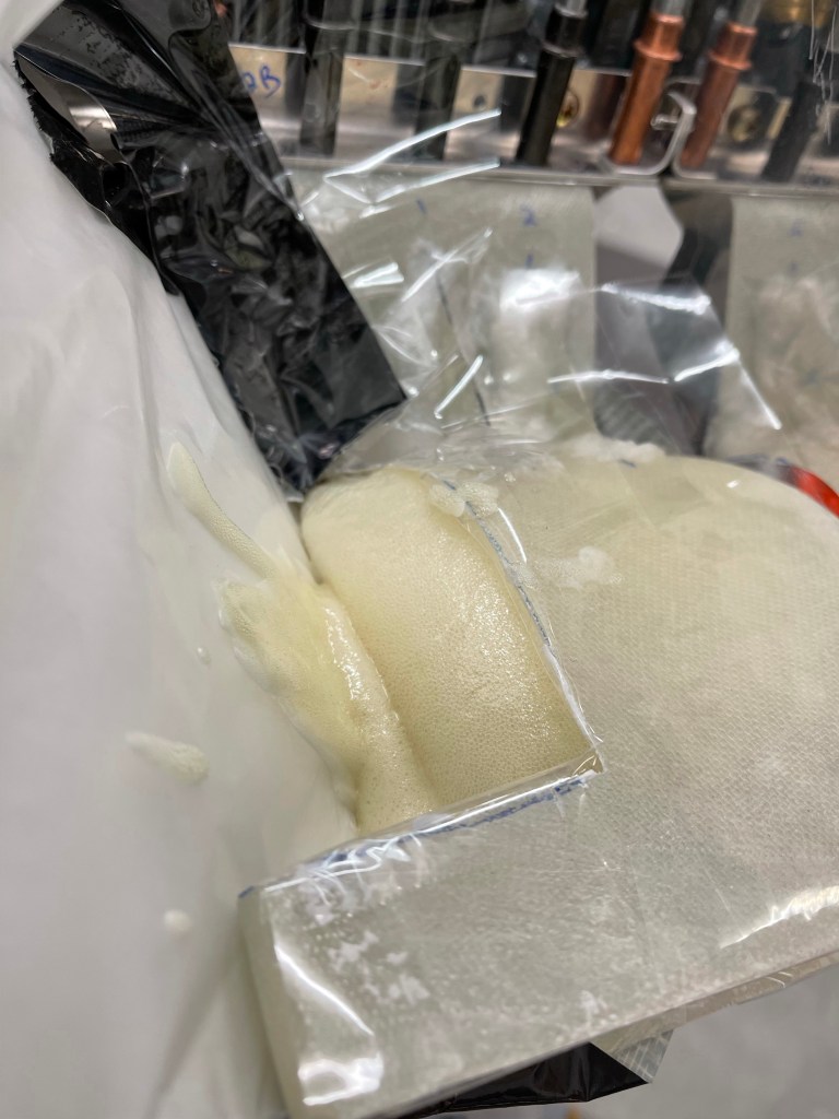
In order to fabricate my own tube.. I decided on using a high density expanding pour foam. To do that, I used poster board covered with wax paper and a bunch of duct tape to form the basic outline of what I was after. This tube would connect the 2 pieces together. The liquid foam would be poured into this and it would expand out to fill out the tube.
Posterboard tube
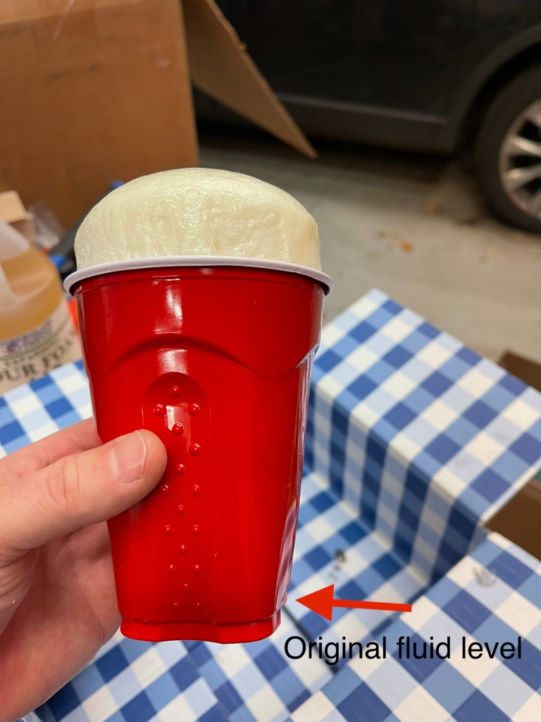
I tested out a very small mix of the expanding foam with Declan. He was pretty excited about the experiment. First the foam I ordered.
I mixed up a very small amount and we witnessed how much expansion happened. Pretty cool!
Declan and I cut up the foam once cured (about 15 minutes) and he was happy stacking the blocks we created.
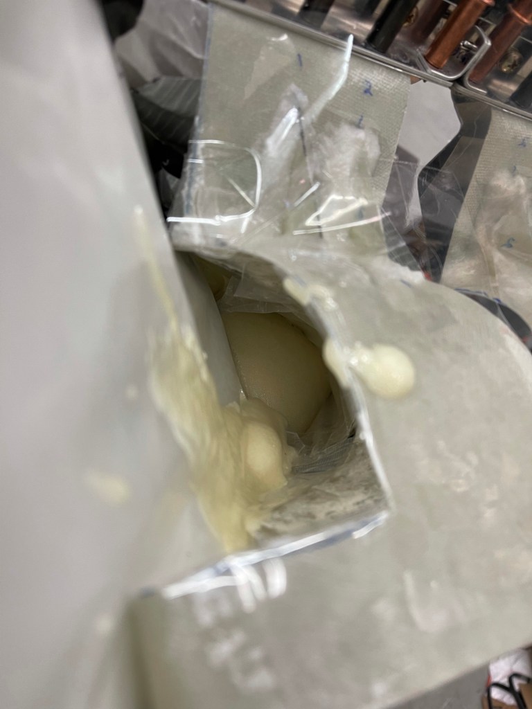
After that experiment Declan was exited to get to work on the foam for the airplane.. So I mixed up an initial batch which seemed to fill up the tube pretty close to full.
After first pour.
You can see the foam found its way out the plenum side too. Of course I put a cap on this filter side, so it wouldn’t go inside the tube.. This excess will easily be cut/sanded away.
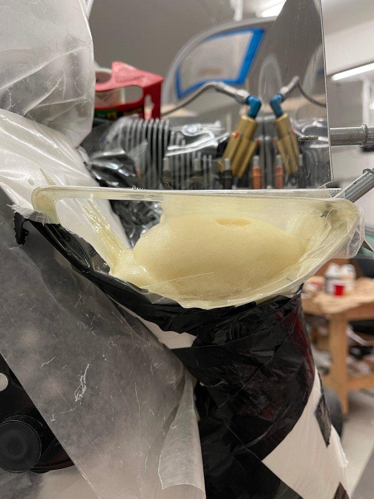
The end result of the second pour.. I captured a short video of the liquid expanding in the tube.
Final pour results
After everything was cured.. I took the poster board off to see the results. Seems pretty good.. Lots of sanding left to do to make this a much smoother tube. Once that is done, I will lay up cloth over the foam to form the custom tube.
A quick pic of the ANL bases installed on the firewall as I finished up placement of most items. There will still be a few others, but I’ve got the bulk of them done prior to installing the Firewall insulation and engine mount.
I also got my oil separator from Anti Splat Aero and the first batch of Air Conditioning parts arriving.
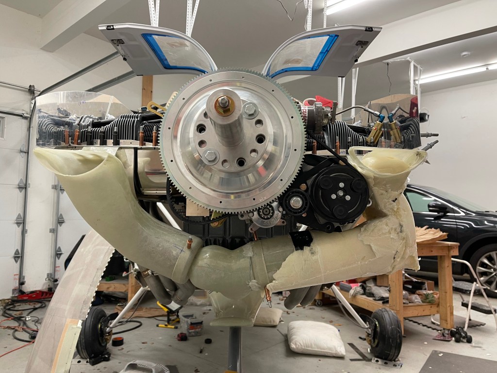
New Flywheel, compressor, and AC parts
That allowed me to place the 2 pass throughs for the AC hoses in the firewall prior to continuing. After a bunch of debate, I decided to route them down the right side of the aircraft. A lot of people route them down the tunnel, but it gets pretty crowded in there, especially up in the front, and you’re also competing against rudder cables and elevator push rods. So I decided to do the right side. The fittings are placed closer to the right side of the firewall.
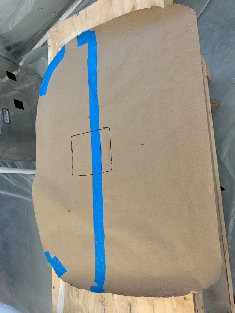
Now that the bulk of the items were placed on the firewall, I made a template for the Lavashield insulation material. I really had planned on using fiberfrax with stainless foil over the top, but I was fighting lots of competing priorities that led me to use this instead. On this template you can see I cut out an area for the recess. I also made another template for the recess so it would be one piece.
Below is the one piece lava shield for the recess area. The larger piece will go over this making the end result look nice.
The larger piece of Lava shield mostly stuck onto the firewall with some major holes cut out. I left the backing on the upper part so that I can rivet the upper forward fuse prior to sticking it down.
I then started placing the major components back on the firewall now that the insulation is in place. Later, I cut out spots around the engine mount locations, as there should be nothing between the mount and the frame. Other things go right over the insulation.
Engine mount held in place for a quick check.
Another thing I tested out is my control servo for the oil cooler. This will allow me to control the amount of air going into the oil cooler with a knob on the panel. This will come in handy in the winter months where I can close it down a bunch and keep the oil temp right at 180 degrees.
Here’s a shot of the entirety of the plans.. followed by where I currently am in the plans. While I’m quite far along, I think I’ve reached the 90 percent done, 90% to go milestone.
Thickness of the plansWhere I currently am in the plans
After putting all the pieces back on the firewall, I decided to re-pressure test my brake and fuel lines seeing I took the connections apart. While this area isn’t a place I disassembled, I was glad I did as I found a minor leak at the post filter.
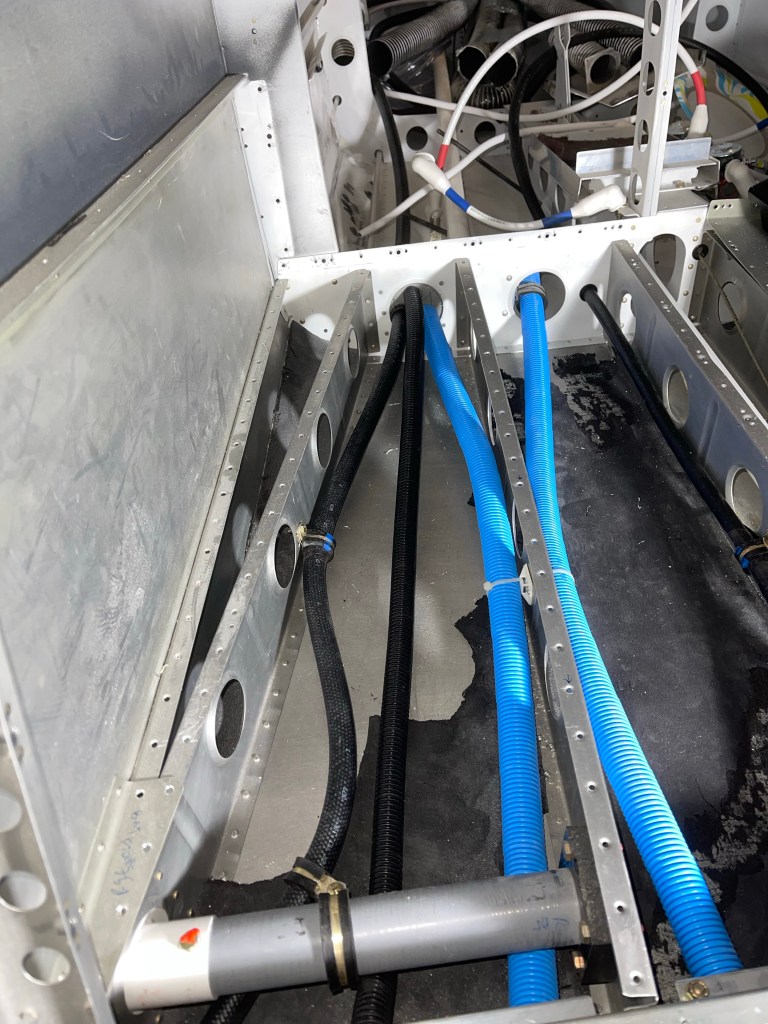
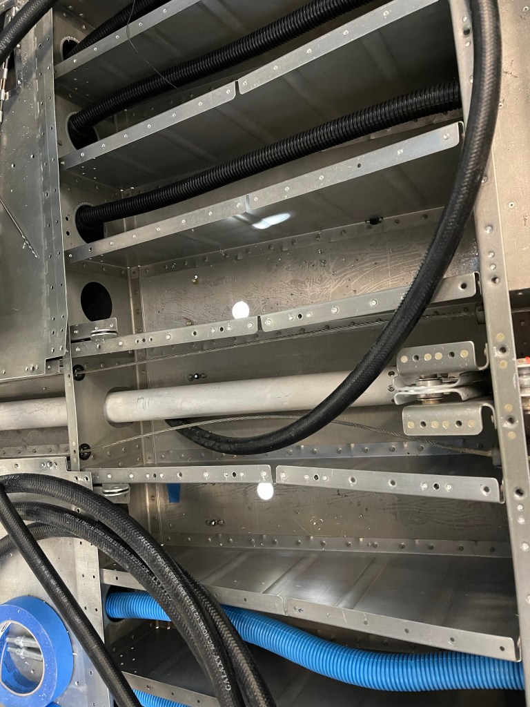
Another task prior to riveting the upper forward fuselage in place is to start routing the Air conditioning hoses from the firewall. It’s a lot easier to do it now while I have better access. Below is an overview of the hoses (2 of them) that go between the compressor in the engine compartment, through the firewall, and to the condenser on the belly of the plane as well as the evaporator in the tailcone.
Some pics of the AC hose (black hose) routing down the right side.
Connections at the Firewall. Down the right side, over the spar
One implication of going down the right side is getting the hoses all the way to the back. This required me to drill out the right baggage and rear seat pans to re-gain access.. Probably took 1.5 hours to get that all done.. Stinks to have to do this after it was all closed up, but such are decisions to add AC later in the game.
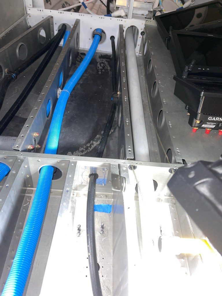
I’ve settled on running the hoses as shown below. The red line depicts the hose that goes from the compressor to the evaporator. The green line depicts the hose from the compressor to the condenser on the belly. For that one, I’ve decided to go across the rear seat front where the hose will be hidden by the flap tube cover, then go into the bay under the rear seat closest to the tunnel, and pop through the rib where the connection comes up from the condenser. I will be adding access panels to the baggage and seat pans to allow access in the future.
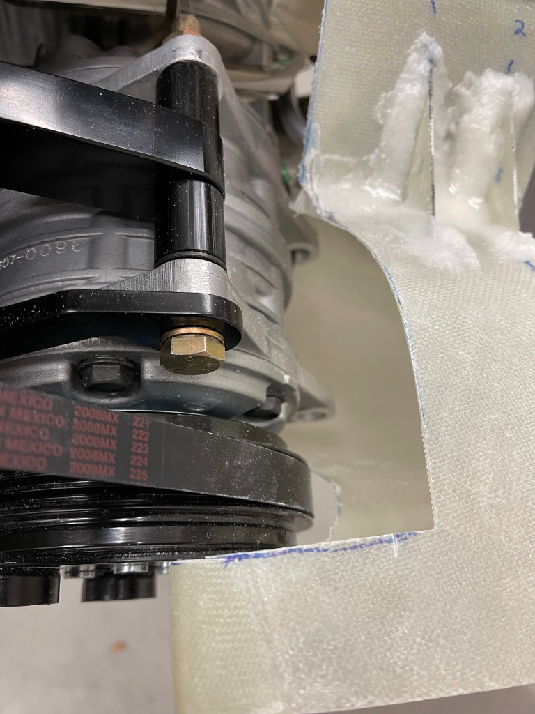
I also have received a curved bar for my engine mount to accommodate the Barrett Cold Air Induction sump. Its pictured below in place of the straight bar it will replace. This will provide some additional clearance needed for that sump. I’ve found a local welder to cut the existing bar out and replace with this curved bar. I’ll be picking that up from him in the next day or so, as it is all done and ready.
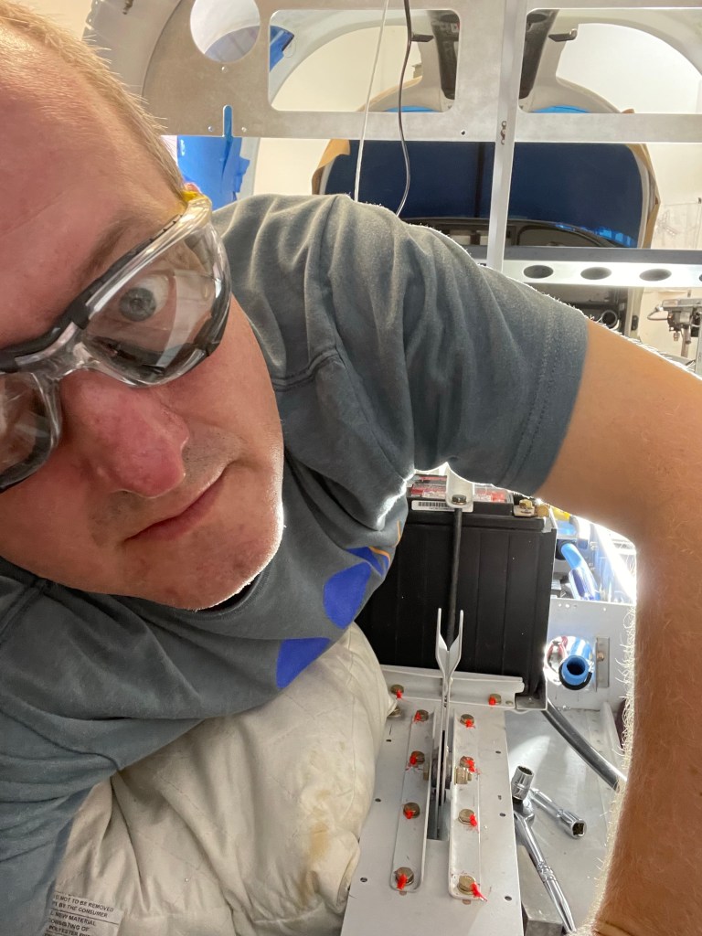
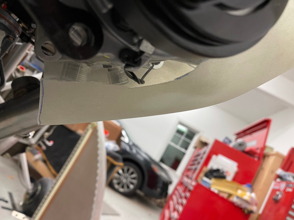
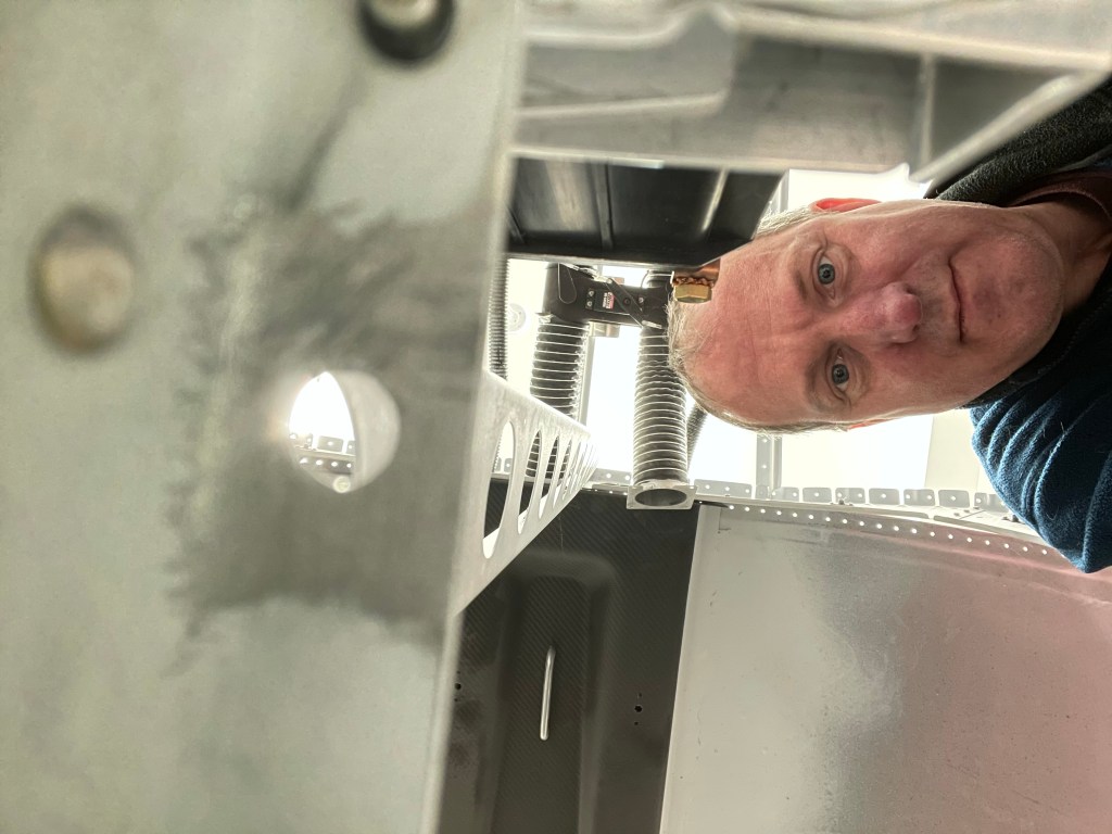
My ugly mug taking a pic of the battery area to see how good I’ve scraped the primer off of the metal where a battery ground cable will be locally connected to the structure.. 🙂
I then used the crimper to crimp the 2 AC hoses at the firewall connections and tightened them up.
Both AC hoses crimped and in place
A separate package arrived a few days later containing the shelf for the evaporator along with the scoop and condenser unit for the belly of the plane.
CondenserCondenser scoopEvaporator shelf (still to be trimmed)
Part of the choice to use the Barrett Cold Air induction sump, involves using a different cowling from Show Planes. It recently arrived and is stored away for early next year after my engine arrives.
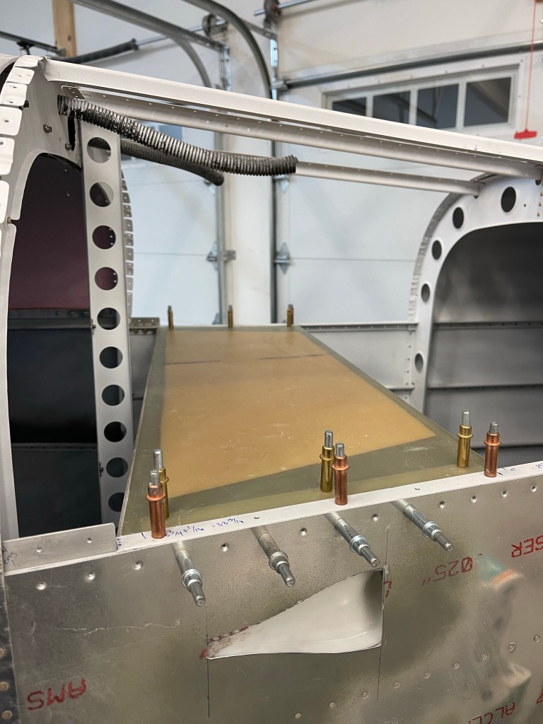
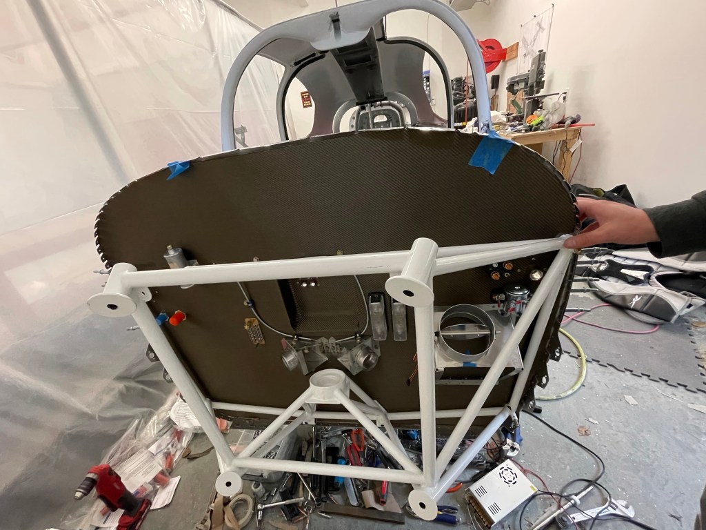
After as much up-front planning as I could do, I was ready to rivet the upper forward fuselage in place permanently. Sometimes you just have to get some of these steps done and move on to allow me to continue to make progress. This might mean that I need to be upside down a little bit more as I finish some things up front, but so be it. My wife, along with a friend both helped me rivet the upper forward fuse in place. It was definitely a 2 person job with one person using the rivet gun and the other manning the bucking bar. Below is a pic of my helper today after finishing up getting the riveting done.
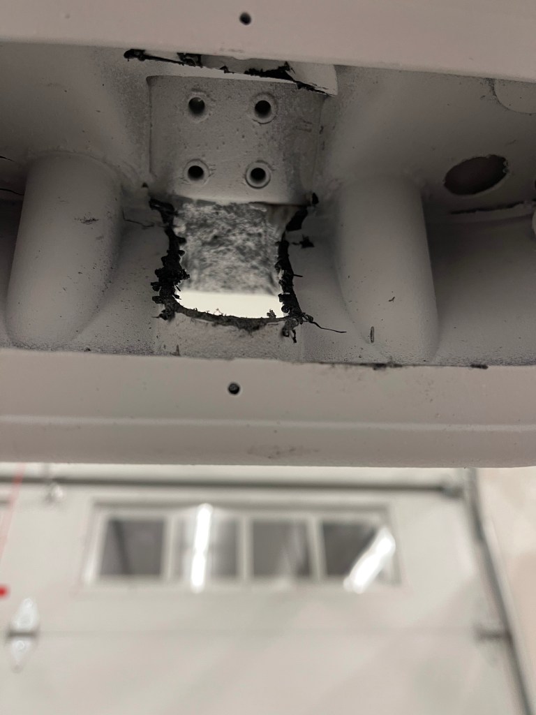
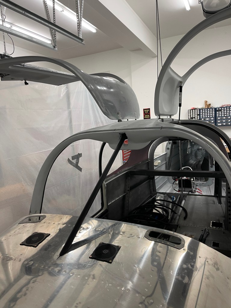
I then continued on to install the center support bar. Prior to doing so, I cut out the center support piece in the overhead switch pod. This isn’t really needed as my switch pod is bonded in and built up all around the perimeter holding it in place. This will allow better access for the nuts as well as the electrical switches etc.. that are planned for up there. It only took 10-15 minutes to get that cut done.
The culmination of the day was bolting the center support bar, which I’ve painted black, into place so I can finish up the fiberglass and interior painting prior to moving to installing the windows and putting the plane up on the gear.