
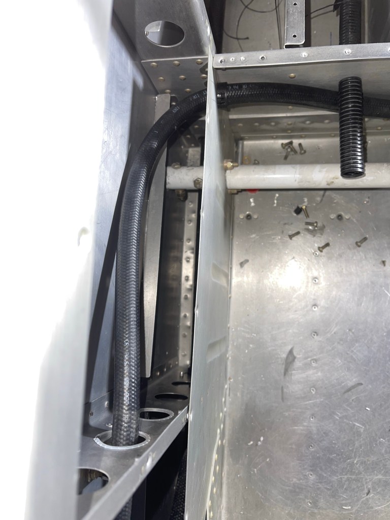
I finished up the routing of the AC hoses down the right side of the fuselage. The hose going all the way to the tailcone dives down towards the floor and goes through the bottom most lightning hole to make sure it doesn’t interfere with the flap tube in the next bay aft. I placed a small piece of angle on the angle attached to the side skin, used nut plates to screw the 2 angles together and then utilized a nut plate to keep the hose from rubbing on the angle attached to the skin.

View of the metal piece riveted in all 4 corners of the lowest lighting hole with a bushing through the center for the hose to pass through.

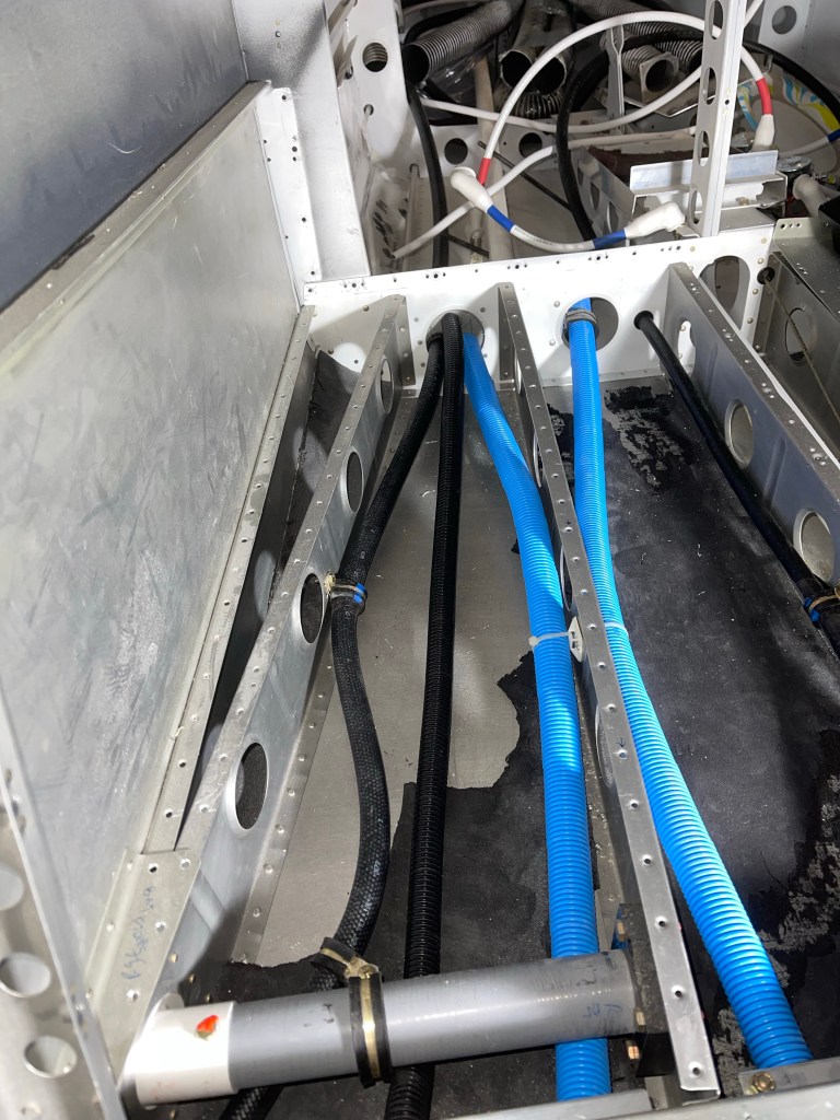
The hose destined for the condenser scoop, goes across the flap tube area on it’s way across the tunnel and to the 1st bay under the left-most rear seat.
Hose continuing to the tailcone under the right rear seat.

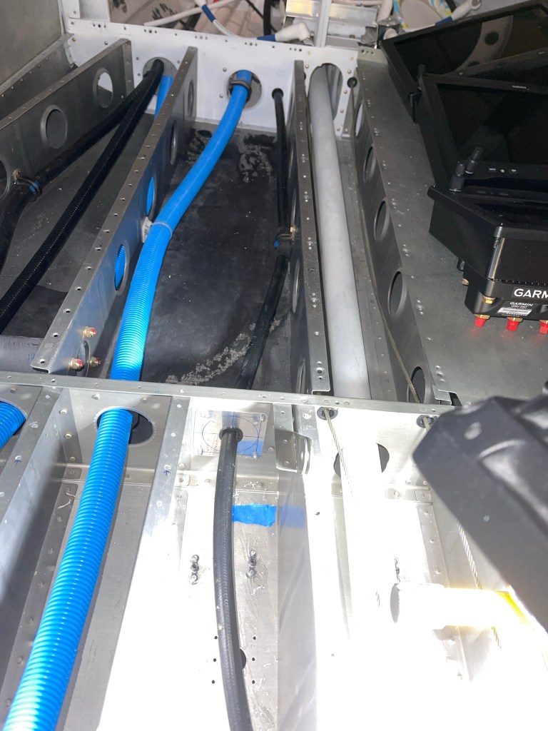
I utilized Adel clamps anchored to the step to route the hose inward and keep it away from the bolt holding the step in place. It then makes its way aft to the tailcone.
Similar for the hose going from the condenser to the tailcone.
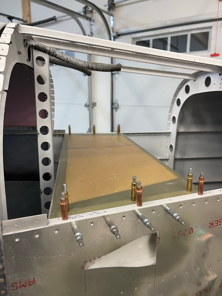
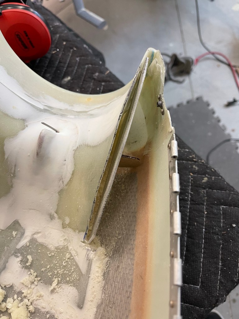
With the hoses done short of crimping on the ends, I started working on the evaporator shelf by using cardboard as a template.

I test fit the cardboard until it was trimmed correctly to sit between the longerons.

I then used the cardboard to mark up the fiberglass shelf and trimmed it, sanding a little bit to get a good fit. Shown here as well are the 3 holes matched drilled into the shelf brackets that get riveted to the longerons.
One other small task was to trim the upper cowl ramps and add a “wall” so that the baffle material could sit in-between the upper air ramp and this “wall” so it has something to push against.
I then mixed up some flox and bonded the “wall” in place with a small “D” shaped piece to provide support against the cowl wall. This was repeated for the other side.

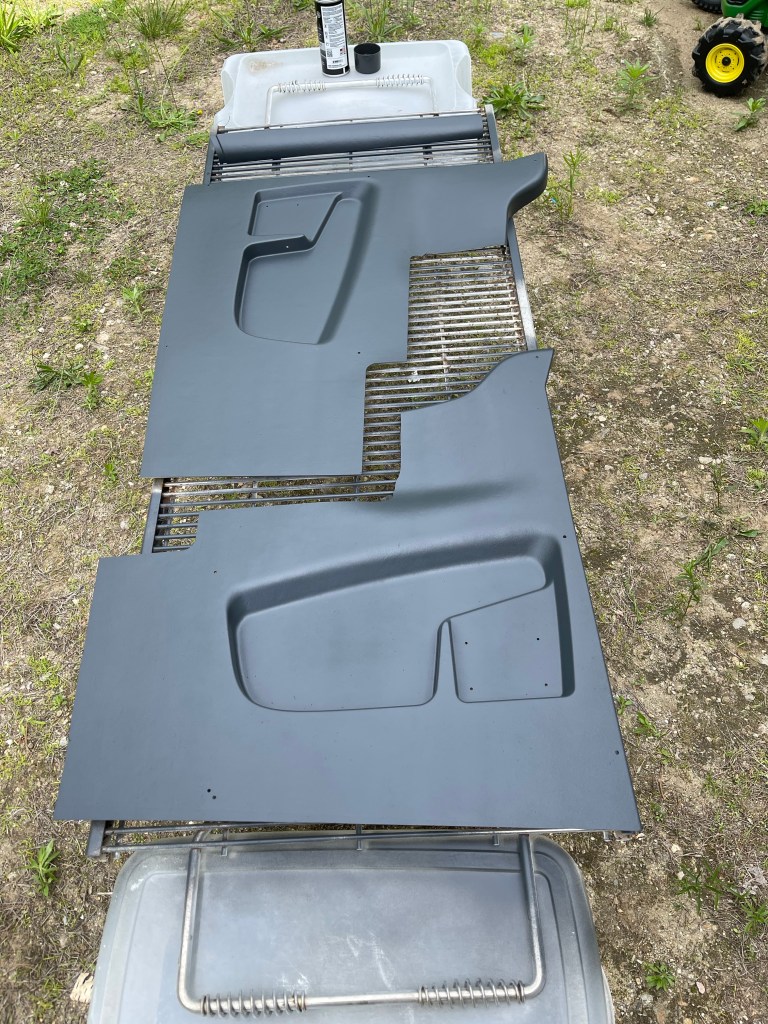
One nice day, I decided to head outside and paint the interior panels. I ordered the lighter tan ones knowing that I was going to paint them a darker color. I think they came out nice!

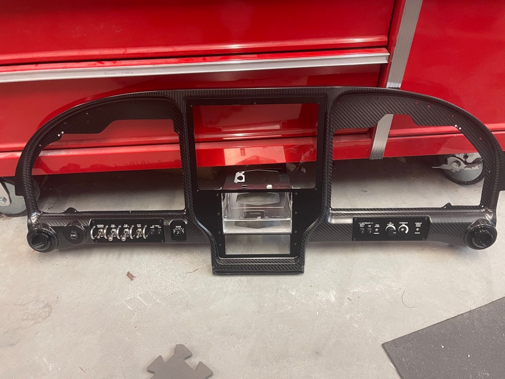
I ran into a snag with continuing with the evaporator install so I worked on completing disassembling the panel. I removed the wiring harness and separated the metal sub frame of the panel from the carbon fiber.

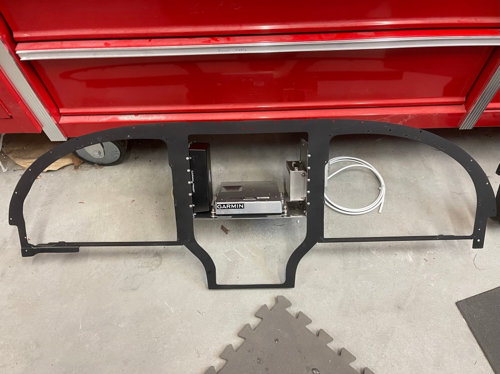
I spent some time getting the metal subframe in place, followed by the carbon fiber panel with the avionics trays. This first test fit was mostly done to mark the sub panel where I’ll need to cut away and reinforce making room for the connectors on the back of the 650 etc.. Not a whole lot needs to be removed just a small rectangle near the bottom and really just for the connectors and so the wiring harness doesn’t get bent too much.

