Working the punch list

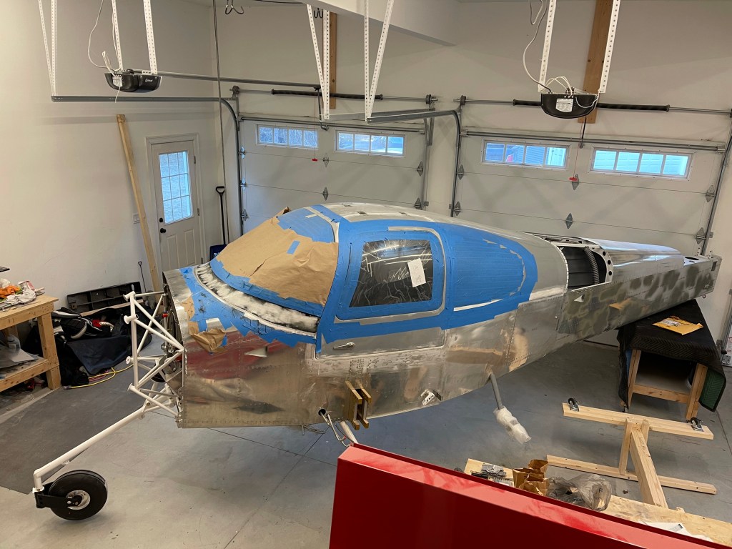
I’ve gotten down to a short enough list of things to do, it was time to write them all down and formulate an approx. schedule to move to the airport. A Punch list of sorts. That approximation had me moving on Oct. 1st. I’m still within about a week of keeping to that schedule. Below are lots of the items that I’ve checked off that list.

  1. Ask Van’s for a bill of sale, fill out registration paperwork, and apply. Done!

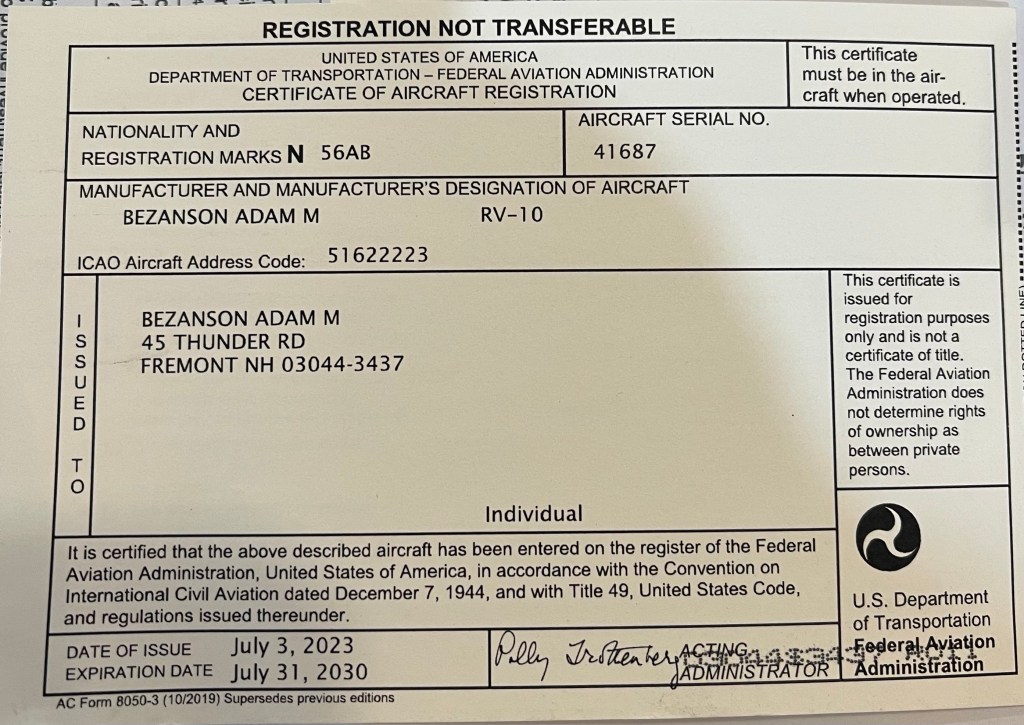
I do have to say, the FAA was rather quick. I know that they expedite new registrations, but still they were quick. The tracking said they received my paperwork on a Sat. So figured no sooner than Monday would they look at it at the earliest. My mid week I noticed they cashed my check. By the end of that week, my info was live with an online lookup, and by the end of the following week, I had the paper cert mailed and in hand.

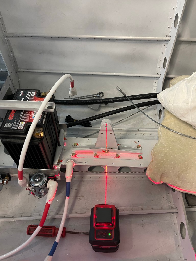
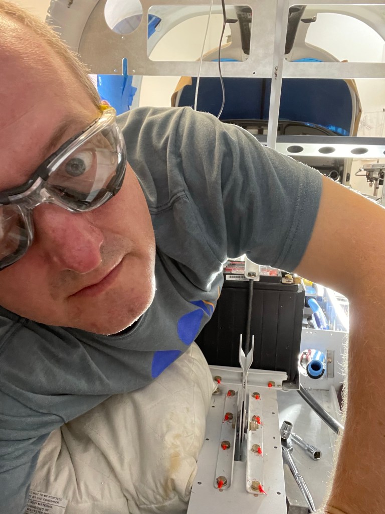
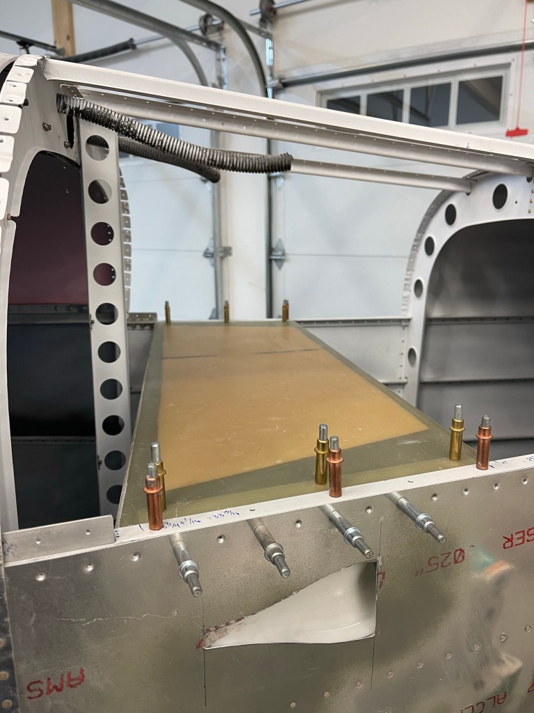
I needed to still drill holes in the cabin top and countersink for screws for the front seatbelt attachment. I wanted to do this before getting the interior done going as well as needing to locate this hole through the headliner material used on the rear ceiling. You drill a 5/16″ hole in the center of the reinforced section of the cabin top. Then countersink it. I bought a countersink bit just because this hole is so large and I didn’t have a bit that would properly do it.

Left hole drilled and countersunk
Screw fits flush
The Countersink bit I bought for these 2 holes.

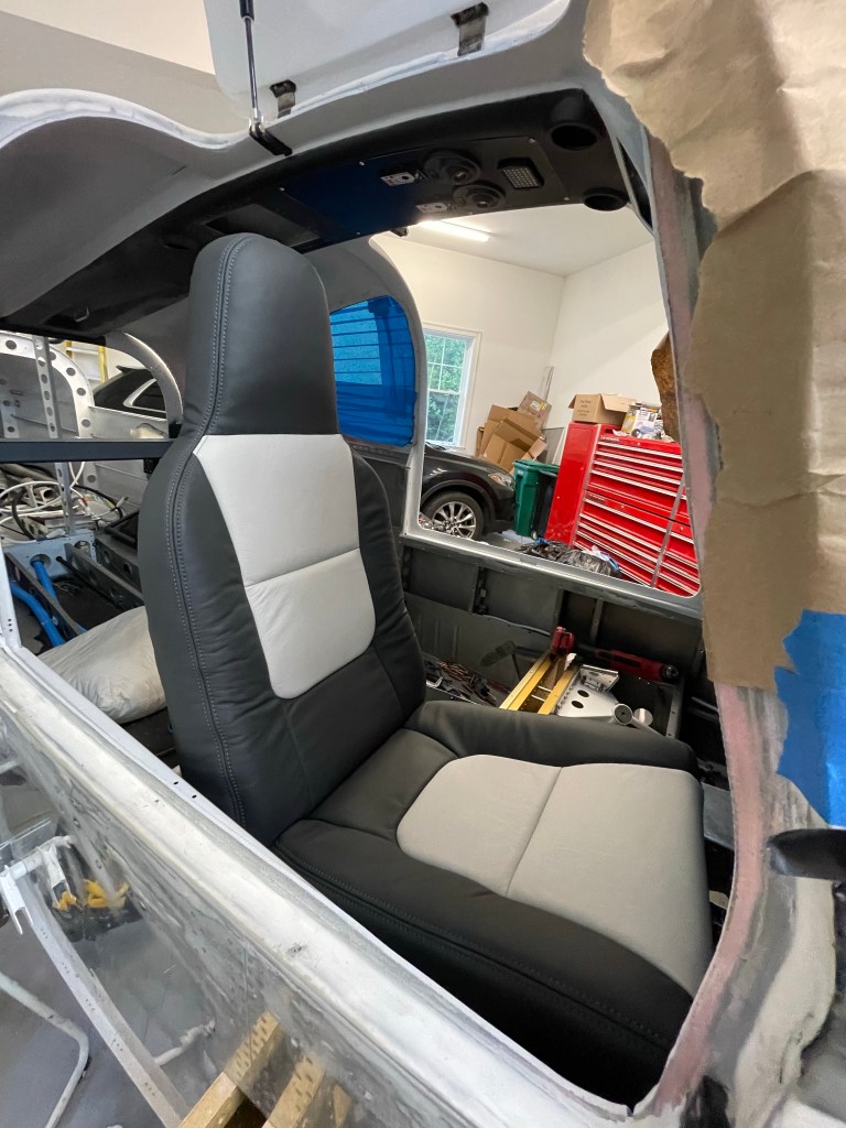
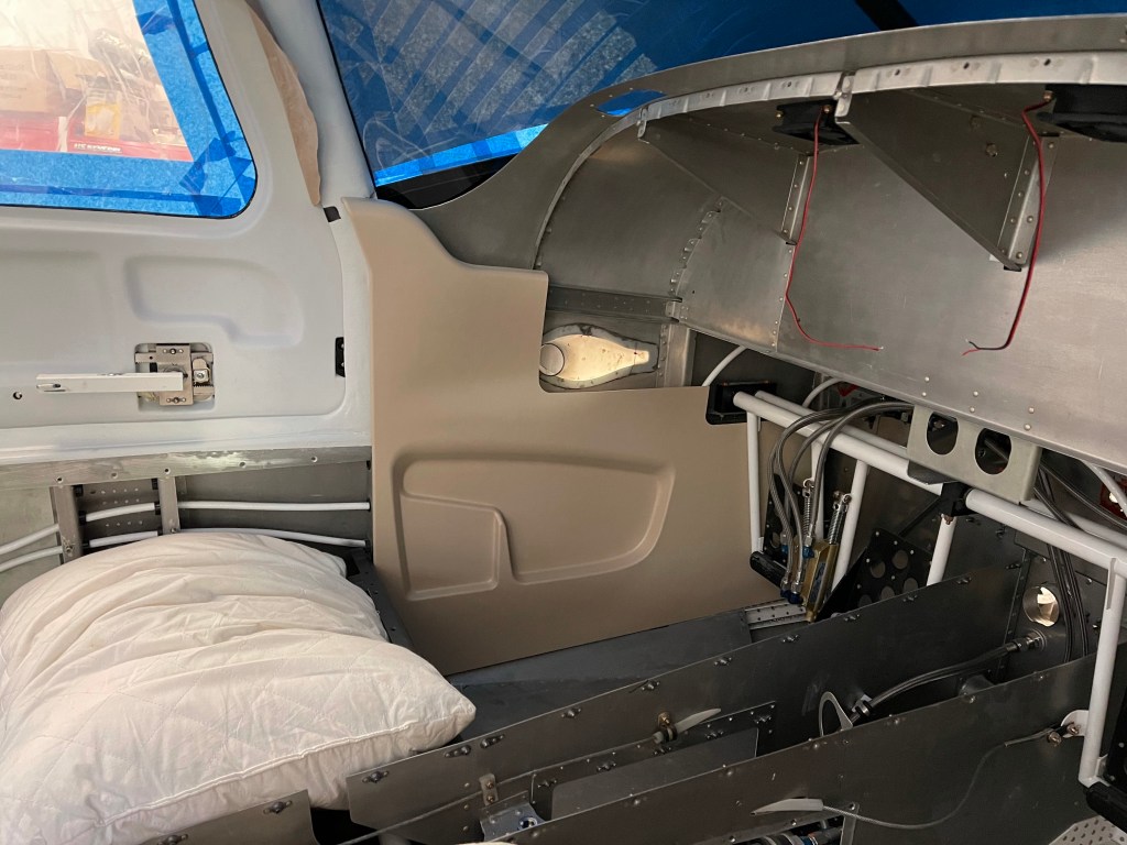
I then started working on interior items. I got the new McMaster door seal in place and installed the door handle plastic.

I then needed to install the seats, but first up were the seat rails. These are pretty straight forward, however, I did do one useful mod to easily remove the seats. I took the seat stop bolts out, placed the out-most rail in place and drilled 1/4″ holes into the seat pan below. I then installed nutplates. This allows you to simply install the aft seat stop with AN-4 bolts (slightly longer bolts are needed) from the gap between the door and the seat with a socket. The seat then glides backwards off the tracks and can easily be taken out. I also took out the plastic slides in the rails themselves and cut the first 1/2″ off to help get the seat tilted down a bit earlier to clear the flap tube cover.

Below is a picture of the seat rail sitting next to where it goes and the 2 new holes with nutplates drilled.

Nutplate mod on seat pan
Seat rail stop installed and is easily removable to slide the seat out.

I also installed the Aerosport Products seat levers to have the seat adjustment knob just under the front of the seats to more easily get to. I didn’t seem to take pictures of that install.

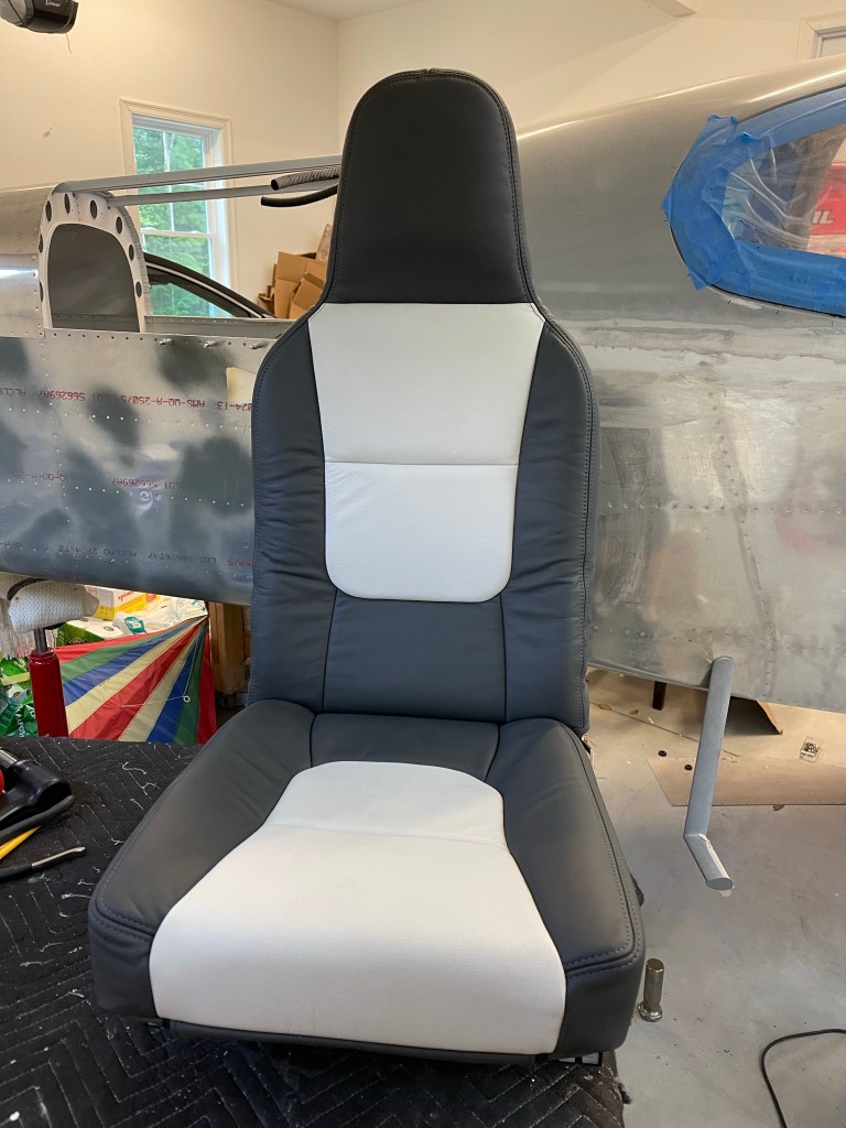
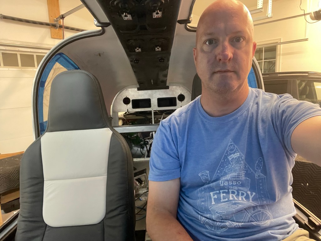
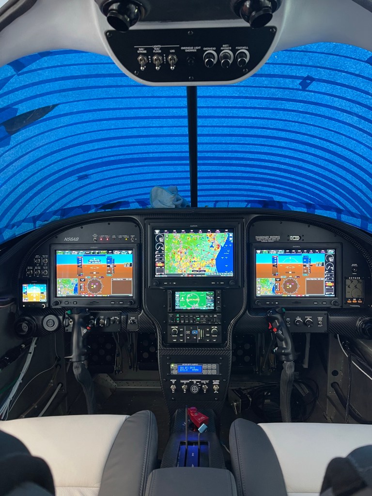
Then I installed the front seats.

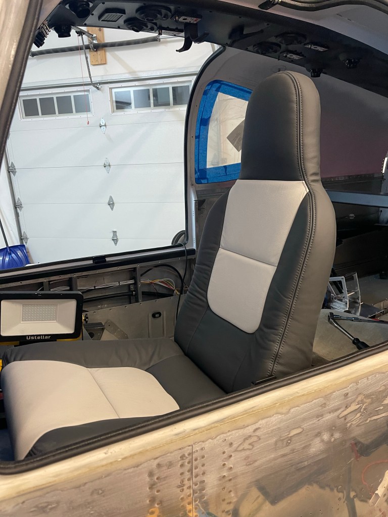
Sticks and stick boots were also test fit.

I will say I’m up much higher than I’m used to. I’ve gotten so used to just sitting on the seat pans themselves.

Testing out the seats
Front seats in and avionics on.
Rear seats are now installed.

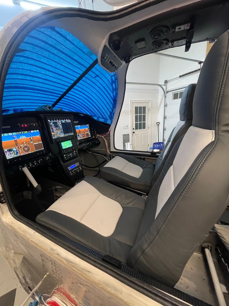
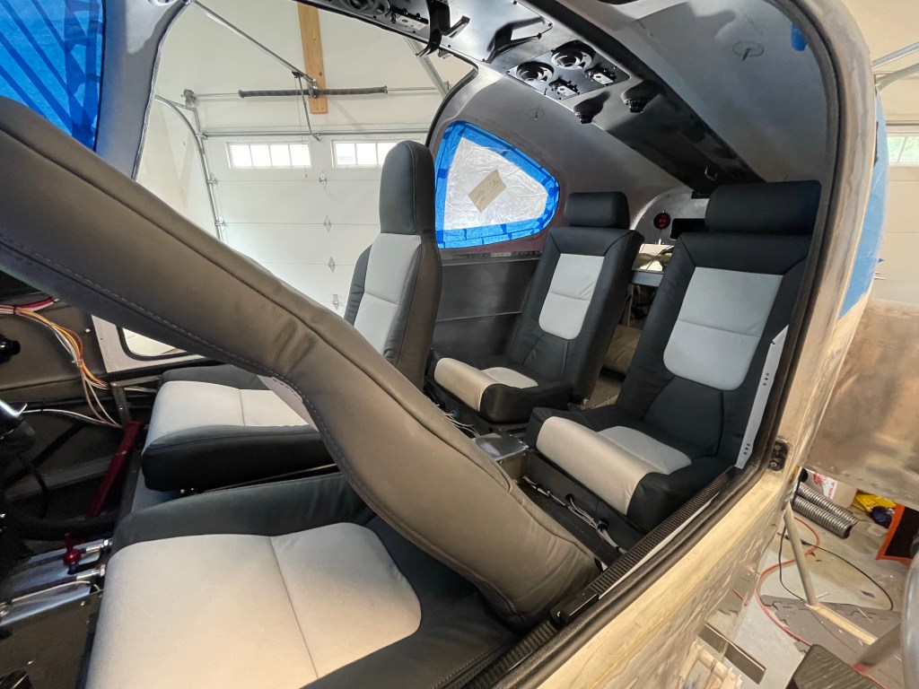
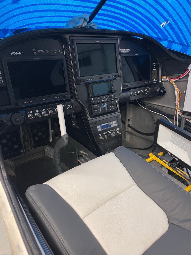
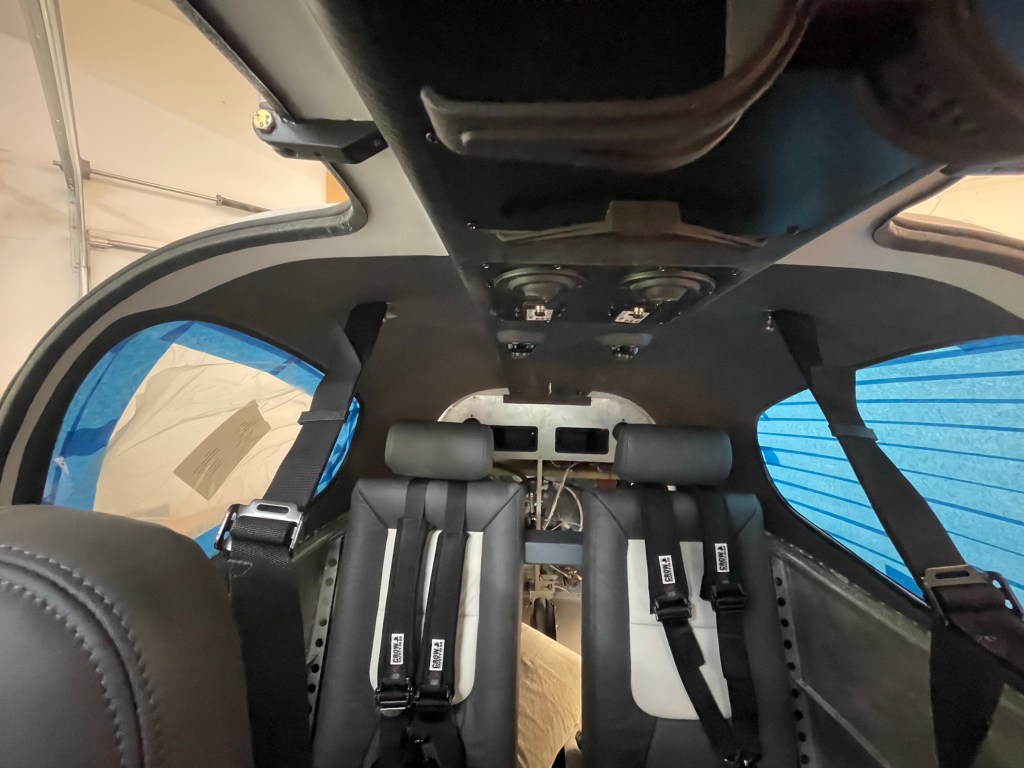
I then got the seat belts installed and the center console loosely in place.

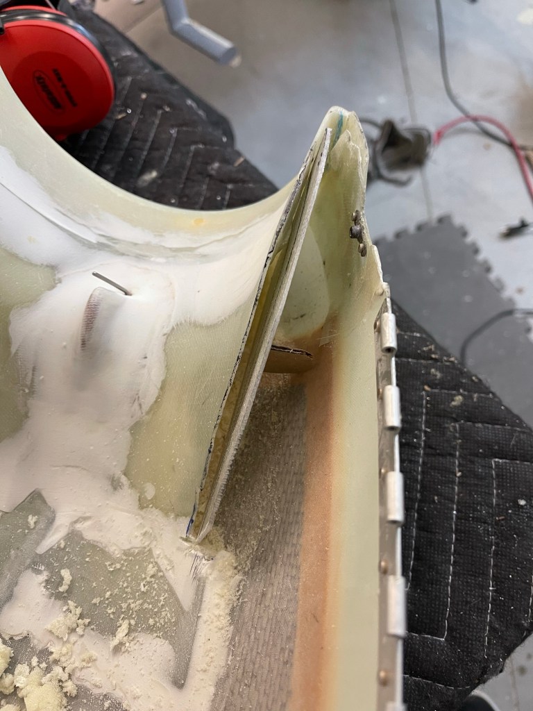
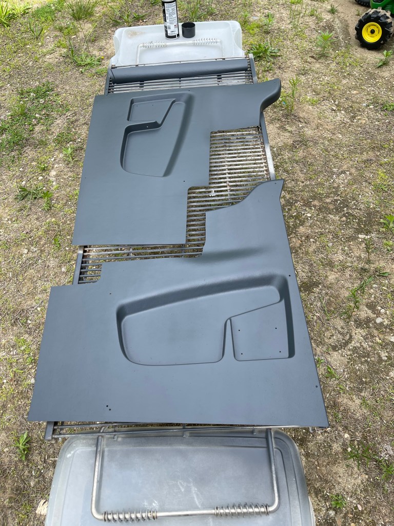
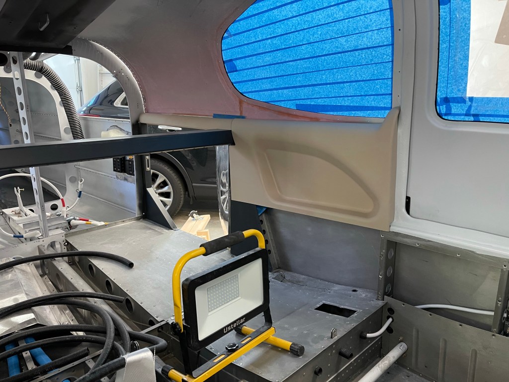
Before I could get the front seat belts anchored to the cabin top, I had to install the Aerosport Products headliner onto the previously trimmed fiberglass substrate. Headliner adhesive from the autoparts store was used to adhere the fabric. I followed the videos on how to make cuts and wrap the material around the backside of the substrate dealing with the inside and outside corners.

Material on substrate
All finished up with the window gasket installed.

I then used some various widths of velcro to install this into the rear portion of the cabin top as shown below.

Headliner material installed.
Just had to take a fuller pic of the panel while I was sitting in the rear seats

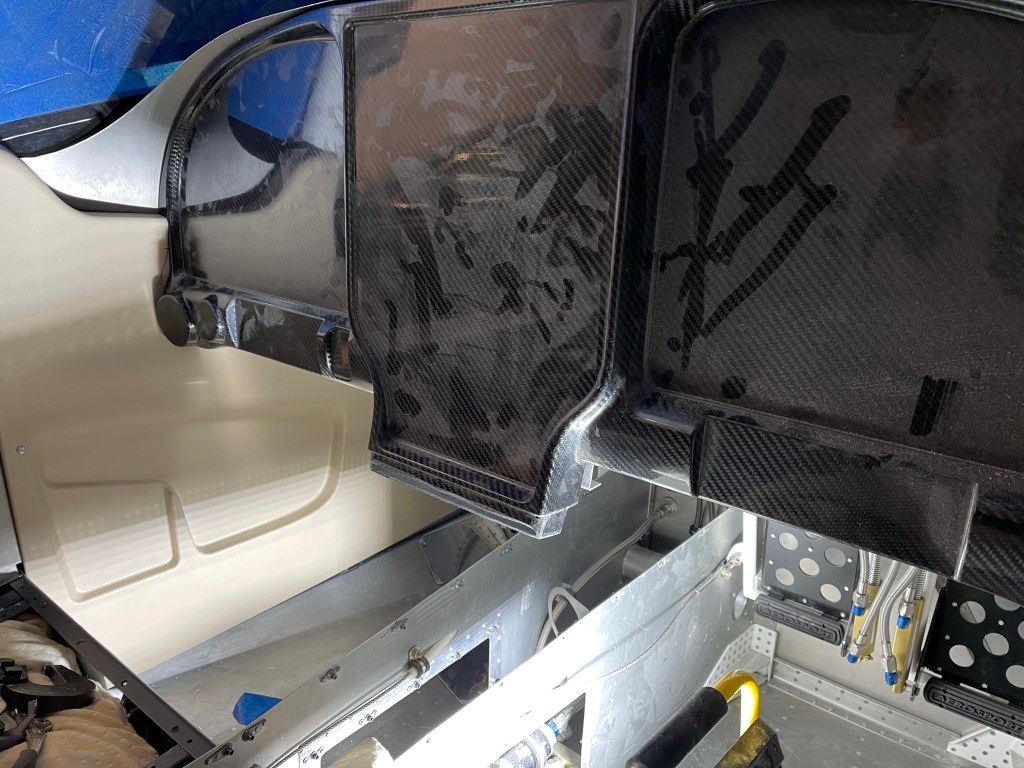
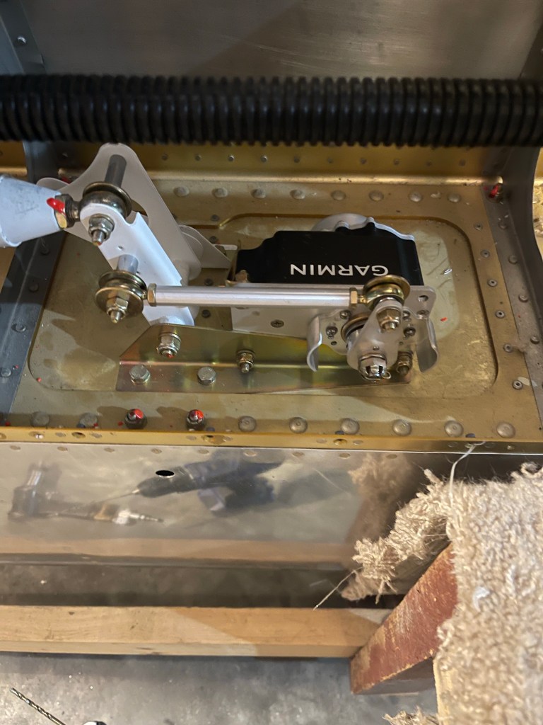
Then some things to finish up in the wings prior to riveting on the bottom skins. I installed the aileron trim motor and springs along with the roll servo.

Roll Servo
Spring of the aileron trim.

Then I mounted the prop once again and got it safety wired and the spinner installed.

Panel work, AC work, Seats, and Tailcone work

My panel items don’t contact the sub panel, but the connectors with wire bundles did, so I cut out a rectangle from the sub panel to make sure there was plenty room for the connectors and wiring bundles with strain relief.

Cutting a relief in sub panel

I fabricated a doubler per Van’s plans

Sub panel doubler

Laid out a hole pattern, drilled, and riveted it in place.

Hole pattern drilled
Doubler riveted in place

I may end up re-connecting the bottom flanges back together once the location of the connectors are in place. I then fabricated supports of the avionics trays and shelf that houses some components to the sub panel for overall support. I used a small angle riveted to the sub panel and connected another angle to it with a couple of rivets. The aft side where it connects to the avionics trays has a screw with a Nutplates for easy removal if ever needed in the future.

I also took some time to fabricate some hinged access doors to get to the AC connections under the rear seats in the first bay. These will secure down using the 2 existing screw locations on the rib. These connections are for the AC condenser.

Access door in rear seat pan
A view of the access to the AC connection on bottom skin

Additional work was started on the AC evaporator unit. First up was to mount the return air ducts.

Right return duct
Both ducts on and interior holes cut
Cap put on

I’m adding a 3″ blower fan to boost airflow into the overhead.

I then placed the flat upper panel from Airflow into position and started rough fitting the evaporator in place on the shelf.

You can see that I will need spacers on the front mounts. I’ve seen several others have to do the same thing. Also I ran into a clearance issue with the J stiffener on the top as shown below. Bill from Airflow said he’s had others run into the same thing due to variation in the units from his suppliers. He’s sending me shorter return ducts to move the unit 2″ forward to solve the clearance issue.

Clearance issue with expansion valve
Manifold is very close as well, but some gap is present

Just before Oshkosh, my seats from Aerosport Products arrived. They came out great! I had to place one into the plane in rough position to see what they look like.

While waiting for AC parts to arrive and needing to finish up some things in the rear of the plane prior to putting the evaporator in place more permanently, I decided I needed to finish some remaining tasks out in the tailcone.

I installed my ELT unit and wired things up to the panel.

ELT in place

I also worked on plumbing my static line from rear to front. This thing needs to go multiple places, so I’ll likely be using a manifold style connector behind the panel vs a long daisy chain.

Static port routing out back.

Pitch and Yaw servo installation was next. I used a laser level to help drill the hole needed for the pitch trim arm to connect to.

Prep for drilling pitch trim hole in bell crank

Crawling into a small and uncomfortable space is always painful. Here I am in the back sort of on my side to drill out 4 rivets so I can attach the yaw bracket to the airframe.. Wish I had waited to buck these 4 rivets, but got them drilled out.

Fun in the tailcone.
Pitch and Yaw servo brackets in place
Pitch and Yaw servos in place

Finishing AC hose routing, Evaporator shelf, front baffle “walls”, interior panels, and test fitting panel.

I finished up the routing of the AC hoses down the right side of the fuselage. The hose going all the way to the tailcone dives down towards the floor and goes through the bottom most lightning hole to make sure it doesn’t interfere with the flap tube in the next bay aft. I placed a small piece of angle on the angle attached to the side skin, used nut plates to screw the 2 angles together and then utilized a nut plate to keep the hose from rubbing on the angle attached to the skin.

View of the metal piece riveted in all 4 corners of the lowest lighting hole with a bushing through the center for the hose to pass through.

The hose destined for the condenser scoop, goes across the flap tube area on it’s way across the tunnel and to the 1st bay under the left-most rear seat.

Hose continuing to the tailcone under the right rear seat.

I utilized Adel clamps anchored to the step to route the hose inward and keep it away from the bolt holding the step in place. It then makes its way aft to the tailcone.

Similar for the hose going from the condenser to the tailcone.

With the hoses done short of crimping on the ends, I started working on the evaporator shelf by using cardboard as a template.

I test fit the cardboard until it was trimmed correctly to sit between the longerons.

I then used the cardboard to mark up the fiberglass shelf and trimmed it, sanding a little bit to get a good fit. Shown here as well are the 3 holes matched drilled into the shelf brackets that get riveted to the longerons.

One other small task was to trim the upper cowl ramps and add a “wall” so that the baffle material could sit in-between the upper air ramp and this “wall” so it has something to push against.

Using some scrap fiberglass to trim up a “wall”

I then mixed up some flox and bonded the “wall” in place with a small “D” shaped piece to provide support against the cowl wall. This was repeated for the other side.

One nice day, I decided to head outside and paint the interior panels. I ordered the lighter tan ones knowing that I was going to paint them a darker color. I think they came out nice!

I ran into a snag with continuing with the evaporator install so I worked on completing disassembling the panel. I removed the wiring harness and separated the metal sub frame of the panel from the carbon fiber.

Wiring Harness removed
Carbon fiber panel with avionics trays.
Metal subframe with shelf for various components.

I spent some time getting the metal subframe in place, followed by the carbon fiber panel with the avionics trays. This first test fit was mostly done to mark the sub panel where I’ll need to cut away and reinforce making room for the connectors on the back of the 650 etc.. Not a whole lot needs to be removed just a small rectangle near the bottom and really just for the connectors and so the wiring harness doesn’t get bent too much.

Aerosport Interior Panels

Couple of small things to finalize about the gear installation prior to moving on to getting the interior panels trimmed.

First was to tackle the hardest bolt in the airplane to install. The bolt that holds down the nose gear donuts. This thing requires a lot of compression to even get the bolt hole to line up. Luckily, I have a tractor. So I strapped the engine mount to my bucket and let the hydraulics do the work. Even still, the bolt was stubborn. I feel for others who have said they’ve had family members hanging off the engine mount while someone pushed the tail upwards while trying to muscle that bolt in place.

Tractor comes in handy!
Hardest bolt installed!

I then got the plane repositioned in my garage. It’s now kiddie cornered across 2 stalls so I have room for the engine to be mounted and still move around it.

I also got the brake lines installed and taped to the gear legs.

Brake lines taped

While I’m waiting for my engine to arrive, I’m knocking off misc items still to do on my list.

I started getting the interior side panels trimmed to be able to paint them. I started with the rear panels as they don’t require too much trimming. I did have some adjustments to do as I did build up the door areas a little more than stock, but the trimming wasn’t too bad.

Left rear and baggage door panels
Right rear panels

There are 4-5 screws that need to be located and nut plates added to hold the panels in place.

Then it was time to tackle the front panels. These require a bit more trimming, especially around the front door frame where I built things out a bit more with micro.

Front left panel in place

One trick I saw used was to use a compass scribe a line matching the contour of the area around the door frame. Trimming to that line, gives a good fit. This marking and trimming around the frame was done progressively until everything fit well. Taking a little off at a time is key here.

I then placed the instrument panel in place to make additional trims around the air vent area until it all fit well.

This process was repeated for the right side. I do have AC hoses routed down the right side, so I additionally had to trim the front of the panel to alleviate interference as the hoses leave the firewall and start their journey down the right side. I can now paint these when I have some time..