Continuing from where I left off. Wiring continued… Pulling wires to where they need to go. Cutting to length, stripping, crimping a pin on, and inserting into the connector.. Rinse.. Repeat! It’s always a fun time contorting myself </end sarcasm/> on the front seat area to get underneath the panel..
Working on some wiring behind/under the panel
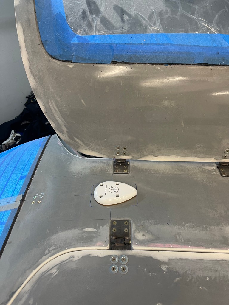
I got the remaining GPS antennas installed.
GA35 between the doors.
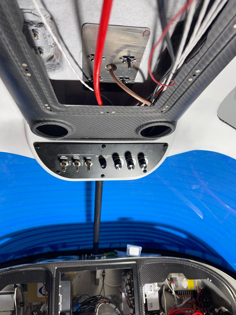
I also got the switchpod finished up and wired down the A-pillar conduit.
Closeup of switchpod
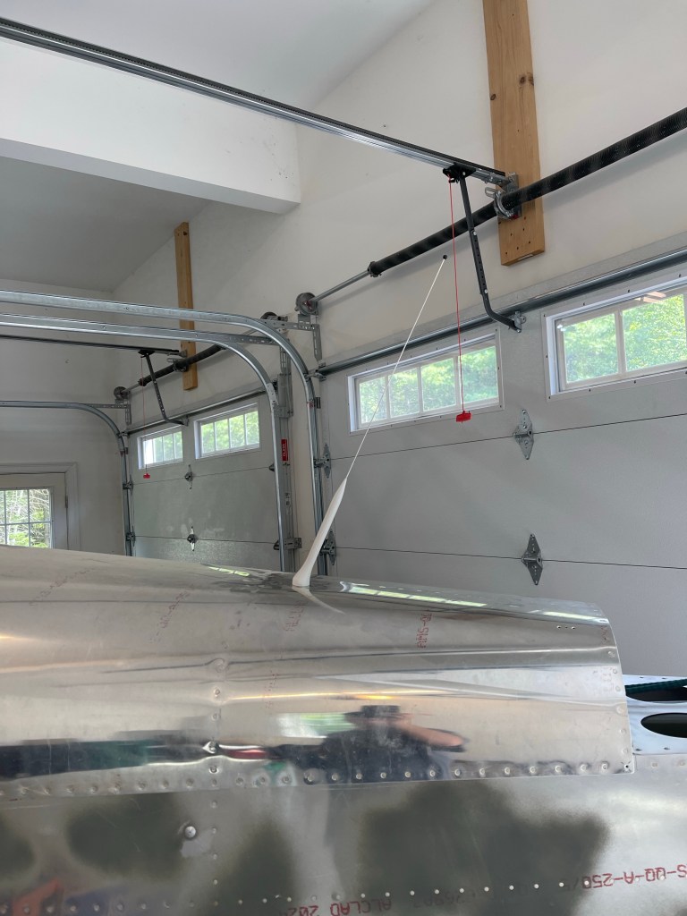
I installed the GA-57X on the aft metal portion of the airframe. Just behind the AC evaporator to avoid interference.
Inside view of XM/GPS antennaOutside view of the GPS antenna
One other thing I wanted to do before closing up the panel was to put the leather glareshield material in place with the two GPS pucks mounted on top of it. Below you can see me getting it lined up properly and the final product.
Getting the material alignedWider view of it all done and tucked under/between the glareshield overhang and the carbon panel.Closeup to see the detailed stitching. Also a defrost fan grate in place.
I then installed the Pitot static and AOA tubing, distributor blocks, and connected them up to the G5, GSU25’s and the alt static switch. I then mounted all the avionics back into place in the panel.
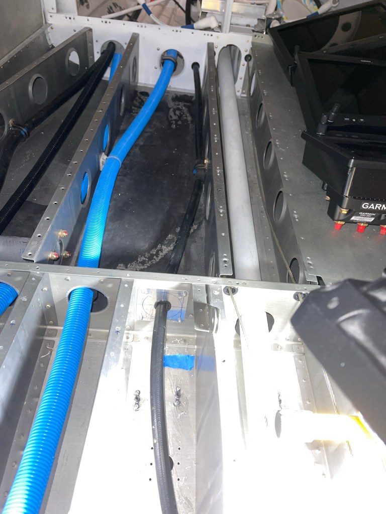
I also decided to pin out the harness that will go out in the right wing. It houses the roll servo and magnetometer. Without it the CAN bus wouldn’t have been terminated properly and communication errors would have happened. I have those things laying in the footwell for now. I’ll have to depin from the CPC connectors later to route the harness through the wings, but that’s easy enough.
A number of triple checks to make sure I didn’t see any shorts between power and ground and making sure +12V was connected to the + side of the battery and negative to negative.. The moment of truth came…..
The panel powered up and everything seems to be working!!! A bunch of wiring work to get to this point, and it represents another major milestone in my build.
I really can’t say enough about the work that Aerotronics did to build this panel. They make it really easy to put it all together.
Now on to pushing forward and getting the remaining pieces finished up so I can get this bird to the airport and signed off to fly!
Not too many updates recently. I’m at a point where it gets harder to take meaningful pictures. So here’s a photo dump of some of the more significant updates over the last couple months
I worked on finishing up the forward tunnel by wiring the fuel pumps and getting the transponder antenna doubler installed with the help of a fellow builder. I then got the cover on and secured the throttle and prop cables and some wire bundles for the headsets in the center console.
I cut out the rear portion of the arm rest where the jacks for the rear passengers and a USB charging port.
The metal plate to cover up the hole I cut and house the jacks.
I also cut holes out in the plastic insert in the arm rest for headset jacks for front passengers.
Jacks installed.
I also installed the 2 GPS pucks on the glare shield in front of the defrost fans.
Left side of the panel area.
Lots of the panel is connected to the rest of the airplane with CPC connectors. Here, I am wiring the P1 connector which houses things like the master contactor switch, starter relay, alternator regulator connections, flap motor connections, fuel senders, door sensors, pitot heat, and boost fan for the AC.
P1 wiring complete.
Secured into place with a clamp.
Wiring like the P1 wiring will continue.. Next post will likely be when I get to the point of powering up the panel for the first time.
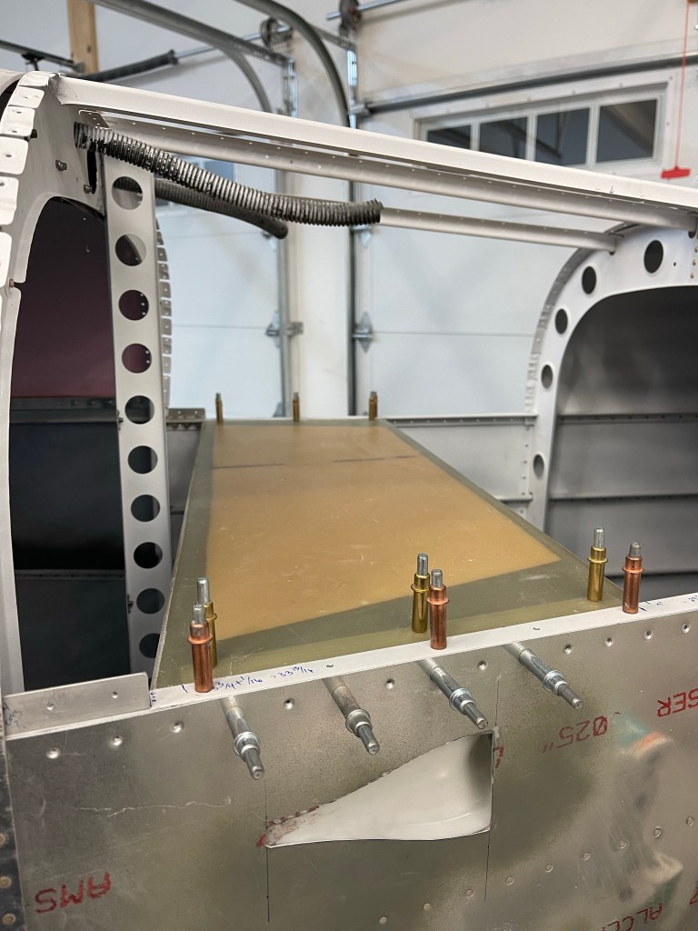
Prior to starting to wire all the FWF stuff, I decided to get my lower console with its side panels and the center armrest with the fuel selector and throttle quadrant installed. The main reason for this, is I need to measure for my throttle and prop cable lengths and I can’t do that with out placing the quadrant.
I first mounted the lower instrument panel console and got it match drilled to the left side panel. The same was done to the right side panel. I used a strap duplicator to match drill holes into the side panels along the top of the tunnel so we can secure them to the existing hole/nutplate locations. Once that was done, I located the center armrest into position and matched drilled 6 holes (3 per side) also to the existing screw holes on the top of the tunnel.
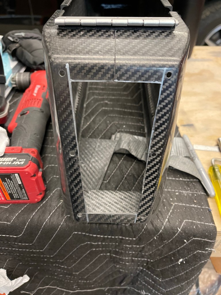
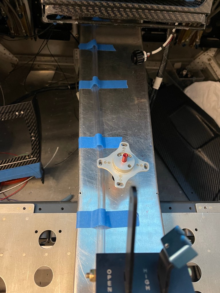
I then cut out the armrest for the throttle quadrant based on the scribe lines. I placed the quadrant into rough position in the armrest while it was upside down and taped it down. I placed masking tape down on the tunnel cover approx. where the quadrant will sit. Then with the center armrest placed down and screwed to the tunnel cover, I marked the legs of the quadrant on the masking tape through the top opening of the armrest. I then removed everything and drilled holes and bolted the quadrant to the tunnel cover. The holes are slotted, so you have some fore/aft as well as up/down adjustment. Getting it pretty close was sufficient. The harder adjustment was the up/down as you don’t have access to the screws with the armrest in place.
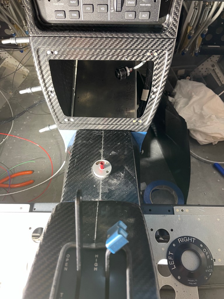
Once that was done, I had previously placed the Andair selector valve more or less in the stock location. So I drilled the hole provided by Van’s up to 3/4″ round hole for the Andair extension arm to come up through the tunnel cover. The extension was pretty close to centered on that hole, so I left it as is.. I used that hole in the tunnel cover to locate and drill the hole in the carbon armrest for the selector.
Throttle quadrant and fuel selector valve hole cut
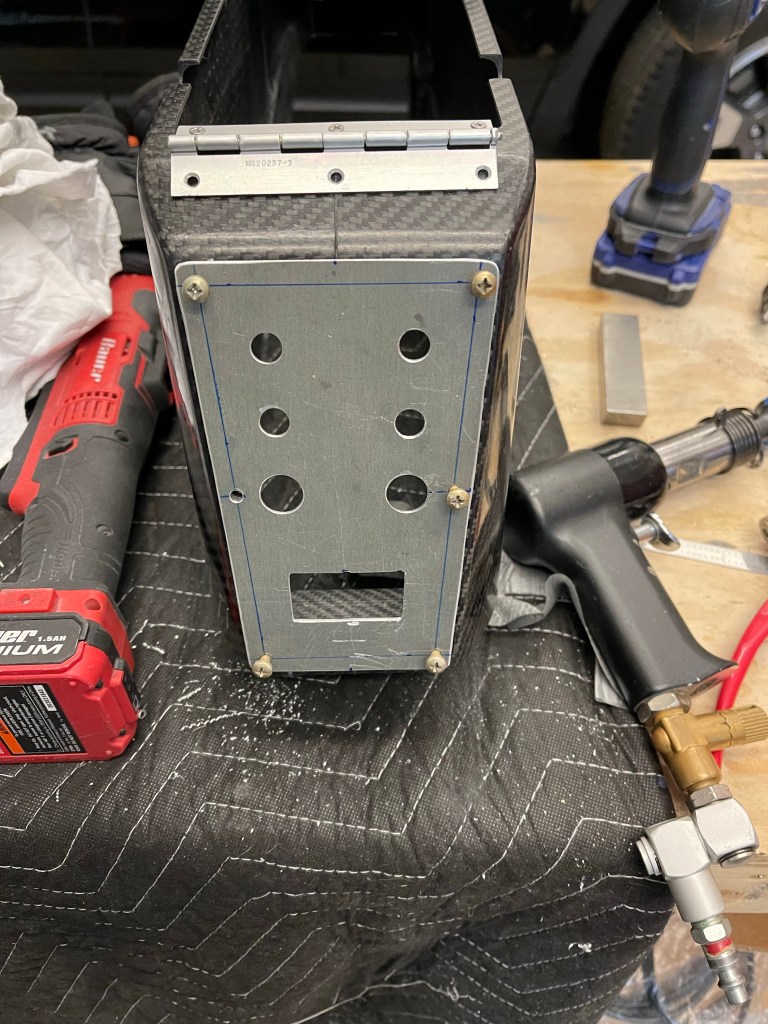
Then the extension arm was cut to the proper length following the Andair instructions and the bottom part of the selector was placed onto the arm and test fit to the hole in the armrest.
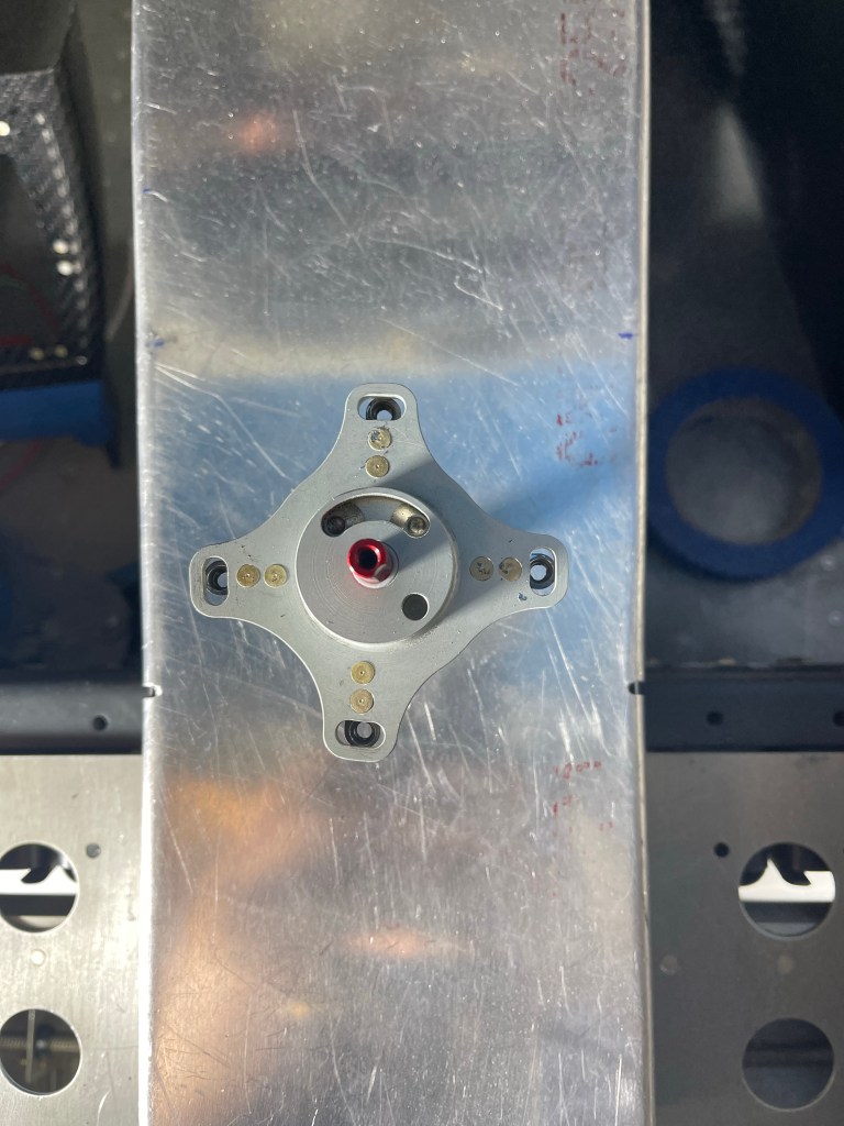
The faceplate was put into position and I used the 4 screw holes on it to drill holes into the armrest. I prefer the orientation to be as shown below. I feel like it’s a little more clear this way as the selector will be pointing left and right for selecting the respective tank. Mounting the faceplate so that the “Lift knob” is right reading, so to speak, would have left tank selection pointing really left and right tank selection still pointing left, just not as much.
In order to be able to potentially remove the center armrest without removing the lower console nor the fuel selector valve, I used nutplates on the piece that sits under the selector valve as shown below. A couple of the holes on the armrest has to be oblonged a little bit to make the screws meet the nutplates properly, but that isn’t a big deal as the faceplate covers that area.
Nutplates on face plate screwdown plate
With all that done, below are the end result at various angles.
I was then able to measure for my cable lengths. I used some vinyl tubing I had lying around to emulate the route for both the throttle and prop cables. I marked around the mid point of the threaded part of the bearing/tie rod terminals and made sure the controls were both full deflection in the same direction (fwd/fwd or aft/aft), I then pulled the tubing out and measured the marks. I did add a couple of inches for some slop or slight variations in the install path that I measured to.
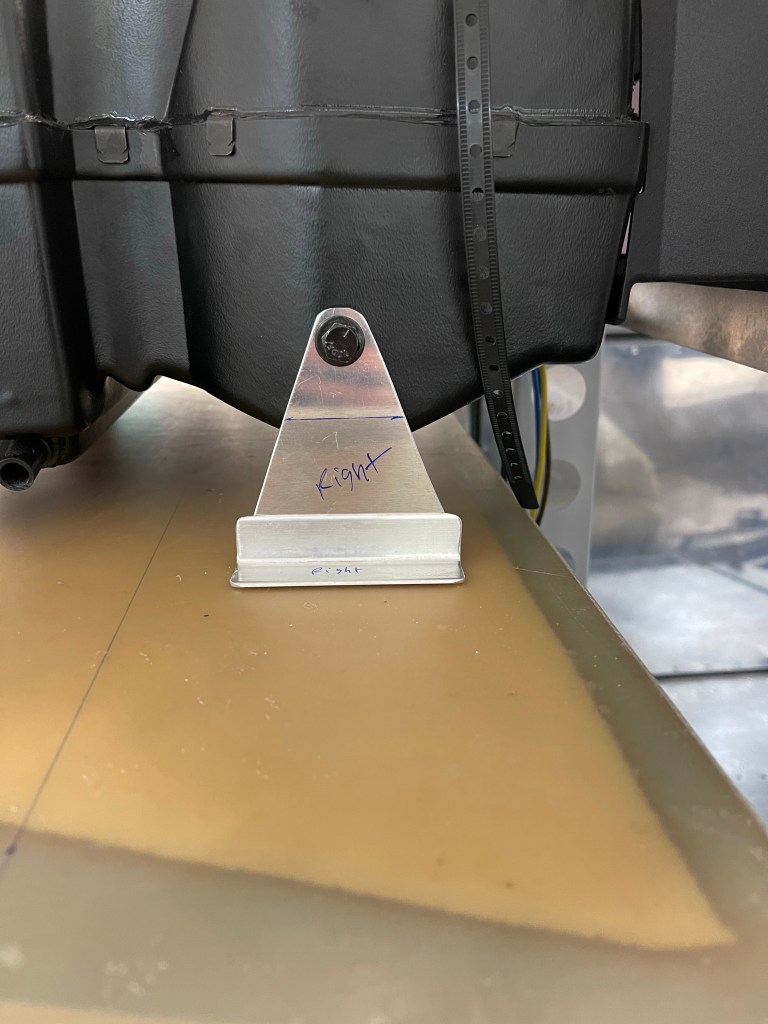
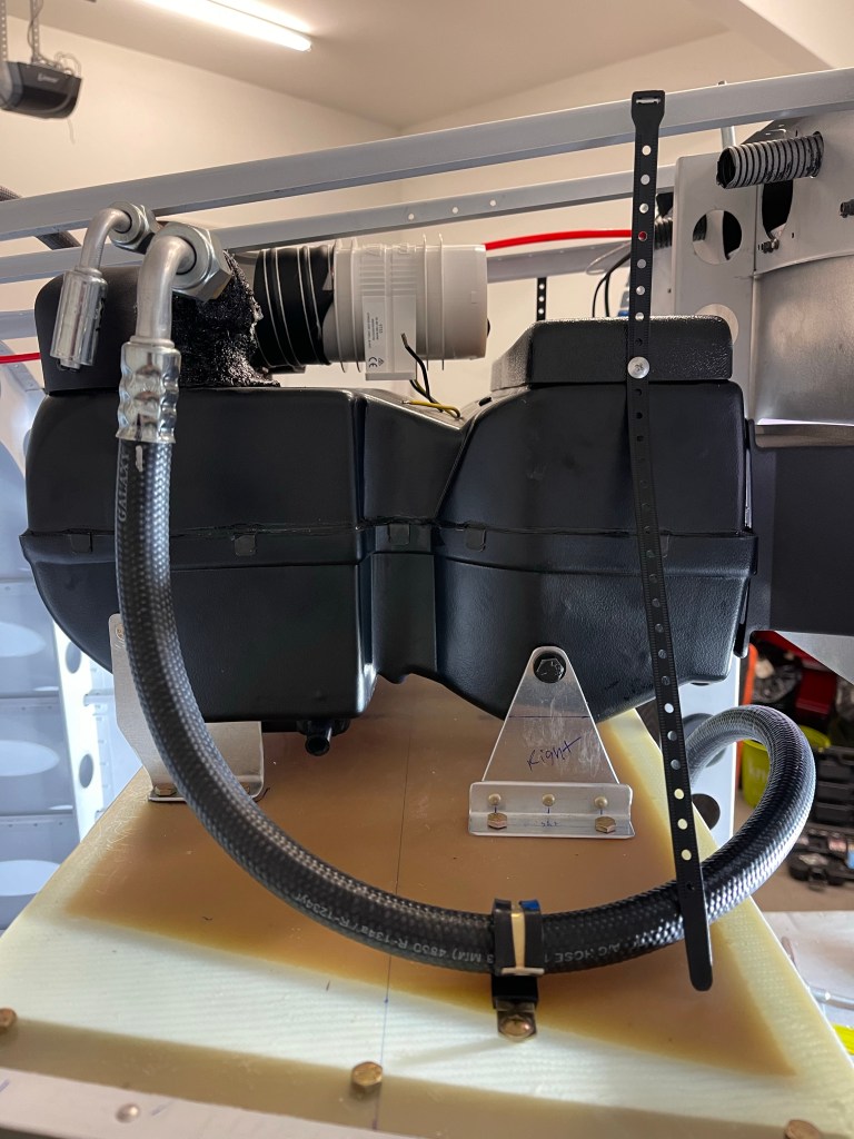
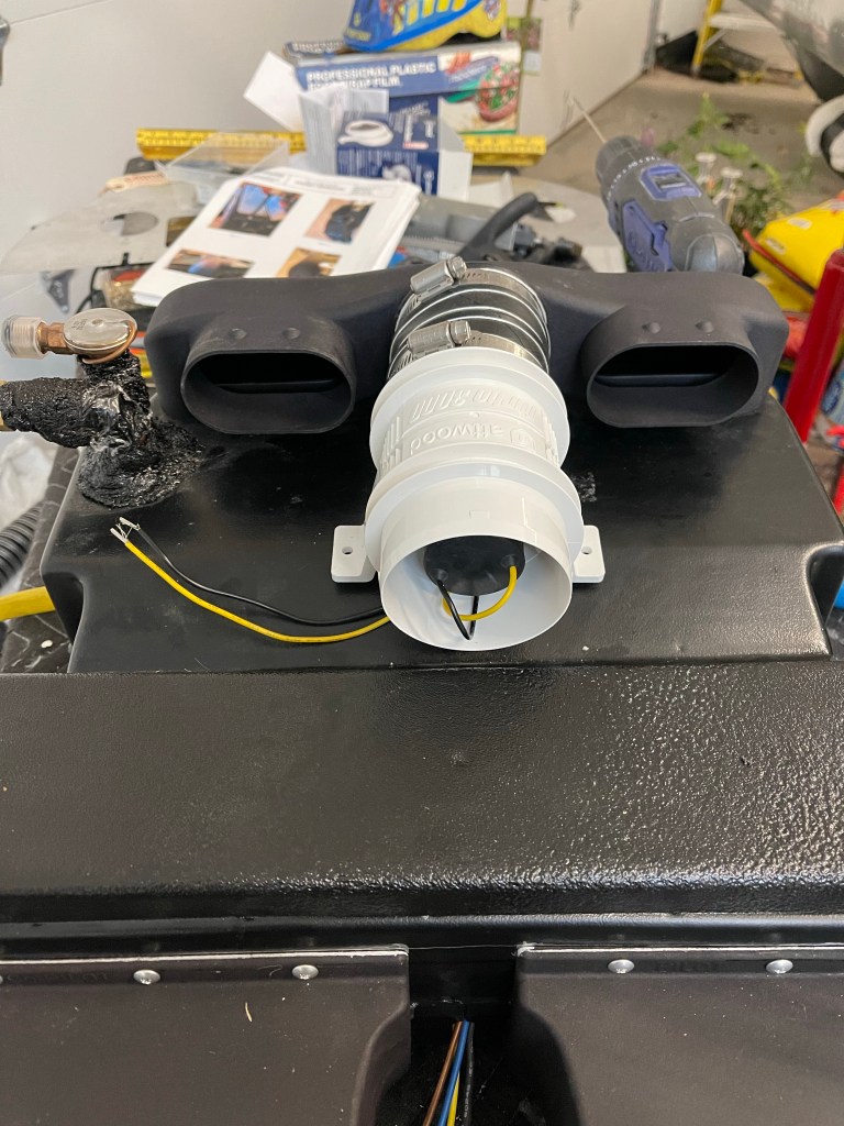
I decided to send my Mountain High bottle back to take the regulator off of the bottle (shown on the bottle below) so I could remote mount the regulator. That will give me the option to take the tank out and get it filled at a shop somewhere. I chose to copy Joe Keys’ installation and mount the bottle to the right side behind the baggage bulkhead. I used an ELT mount along with some angle and flat 1/8″ stock aluminum bar. The angles were mounted to the J stiffeners and I used one hole of the ELT mount for attaching the mounting brackets. It’s hard to see in the pictures, but I used 1/8″ flat aluminum bar between the bottle mounting bracket and the angle/ELT mount to Secure to extend as far as I needed to and attach to the structure.
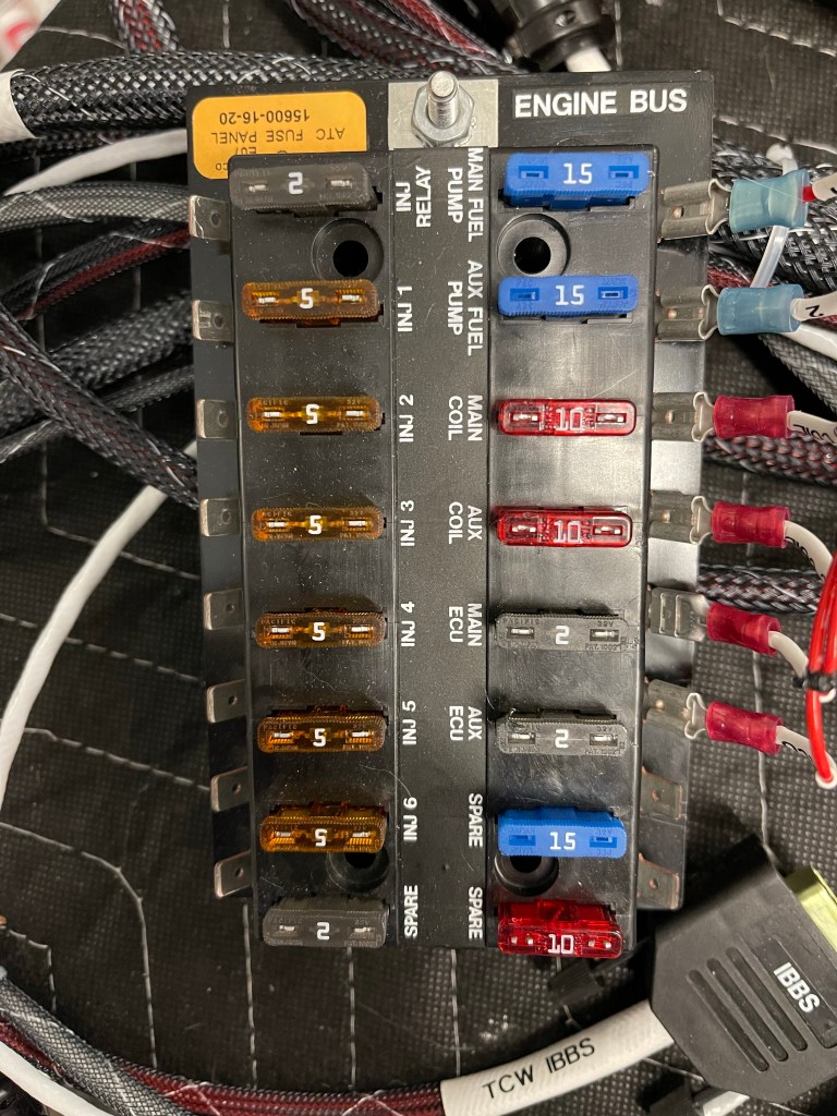
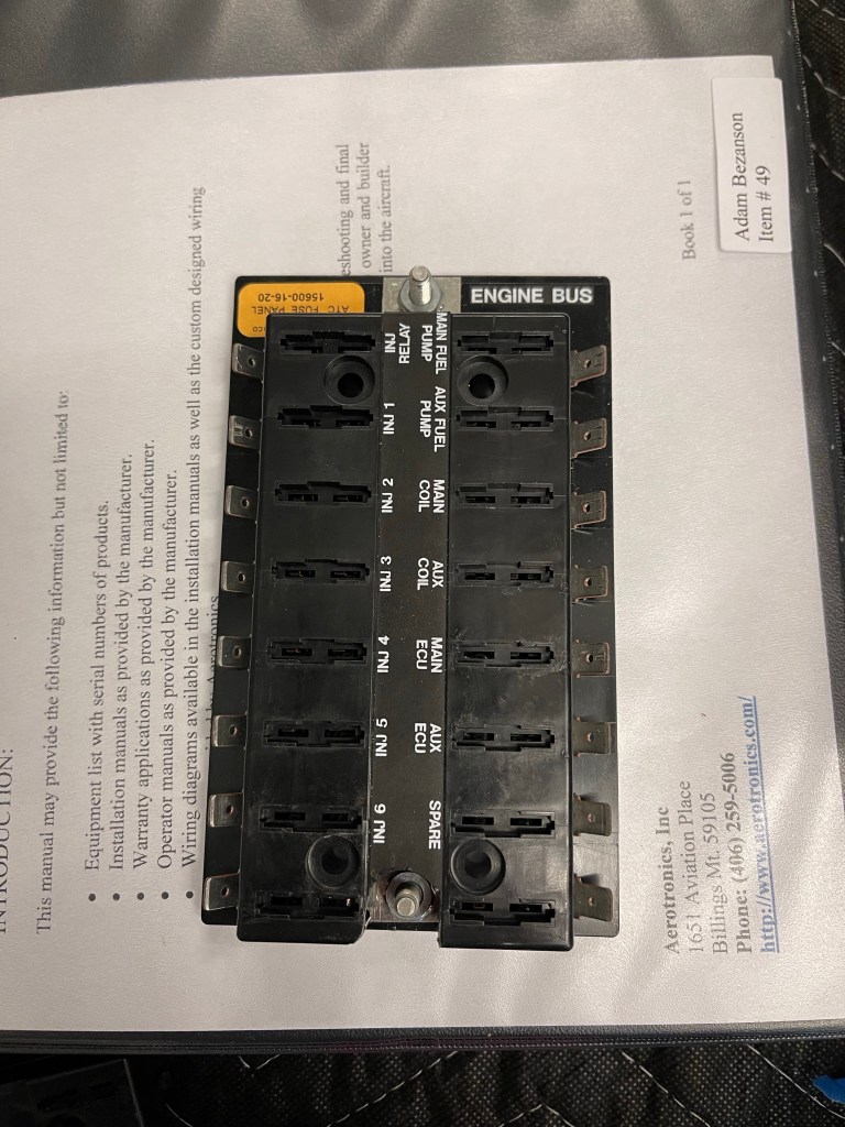
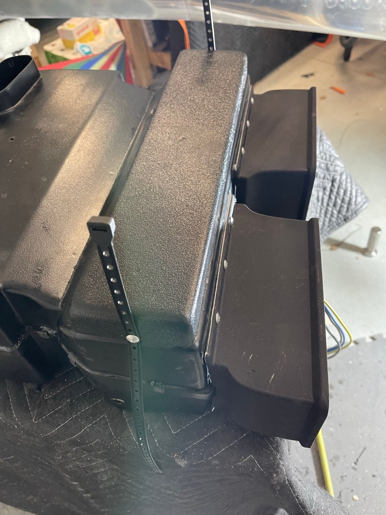
In somewhat of a paranoid redundancy of my engine bus move, I decided to modify the fuse block to add a 2nd stud. The unit has a spot (both a hole and an indent in the plastic) for a 2nd stud.. it’s just not exposed. Below is a picture of the fuse block as it came to me.
I popped the top open and inserted a second stud and then drilled the plastic to expose the stud and be able to tighten down the nut. This will allow me to have the 2 separate feeds of the engine bus connect to different locations protecting against a nut coming loose or something breaking from removing power from the fuse block.
Fuse block modified for 2 studs.
I then moved on to more AC work. I got the skinnier return ducts from Bill and installed them. This moves the whole evaporator forward to give more clearance to the J stiffeners on the top.
Skinnier return ducts installed.
With those installed, I positioned the evaporator, and fabricated new forward brackets with an angle and some scrap metal, seeing it sat much higher than the bracket provided to me and they didn’t reach the shelf. This was a suggestion from Bill.
Fabricating new forward brackets
I spent some additional time routing the hoses to the evaporator unit with the service ports easily accessible by taking the lower baggage bulkhead off.
AC hose routing to evaporatorAC hose runs with service ports shown. Hose to the dryer unit.
Then it was on to antennas.. More in the category of finishing electrical runs out to the tailcone. One of the things I had yet to finish was mounting the NAV antenna on top of the Vertical Stabilizer. I fabricated a doubler plate and drilled holes in the skins at an angle to accept the cat whiskers.
I sanded down a long wooden dowel to a point in order to insert nutplates up into the VS to hold the antenna puck in place. I’ve also seen people use a rod threaded for the 10-32 nutplate as well, but this worked okay too.
NAV antenna in place.
ELT antenna was next. A lot of builders try to mount this inside under the fiberglass. Some DAR’s, including the one I’m using, want to see this external to the airplane.. so I decided to just bite the bullet and put it just forward of the Vertical Stabilizer. I fabricated a doubler, riveted it to the skin, and mounted the antenna in place.
ELT antenna.
I also utilized another ELT mount on the left side to mount the diode with it’s heatsink and the Battery Bus relay. Shown just below and aft of the ELT.
Then it was lots of panel wiring. I first got the remote transponder mounted on the left side with some angles added front to back.
Remote Transponder mounted.
I mounted all the needed components not already on the avionics shelves to the sub panel shown below.
Subpanel components mounted.
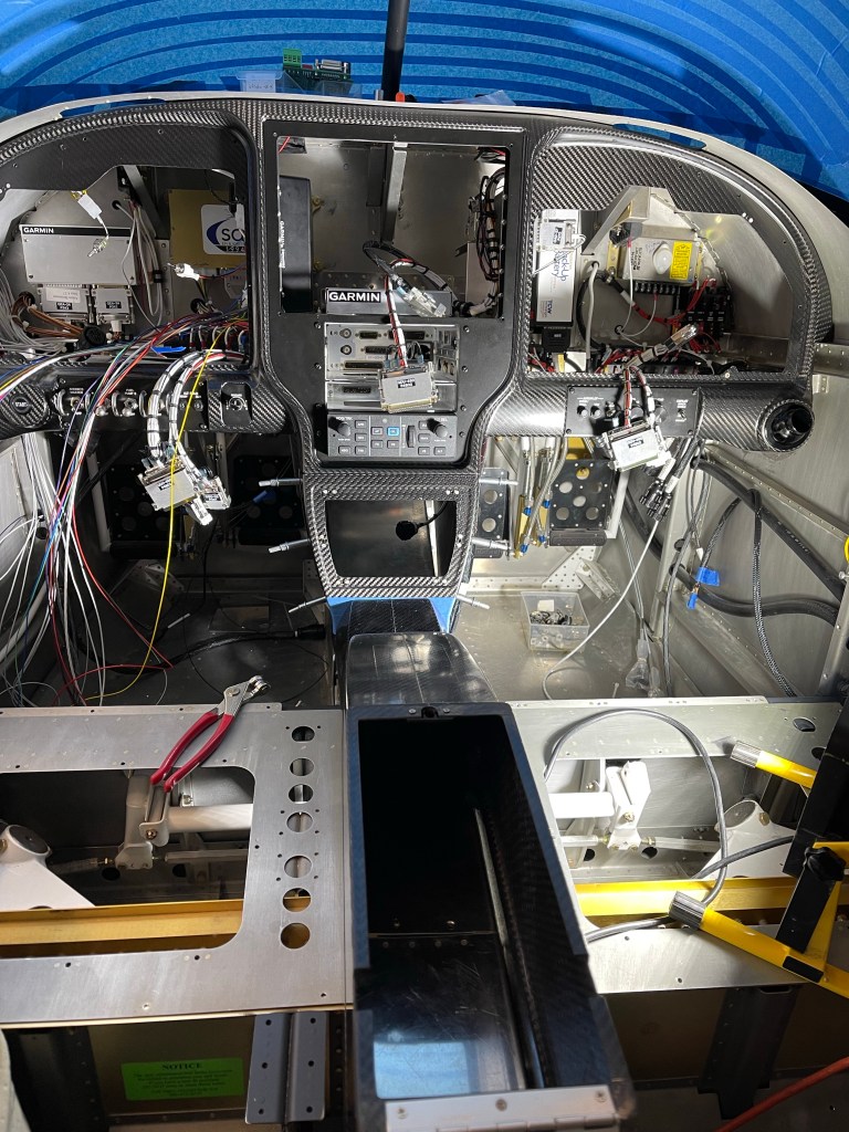
I then put the metal panel frame and outer panel back in place and got the wiring harness re-attached to all the switches etc..
Panel wiring stats now!
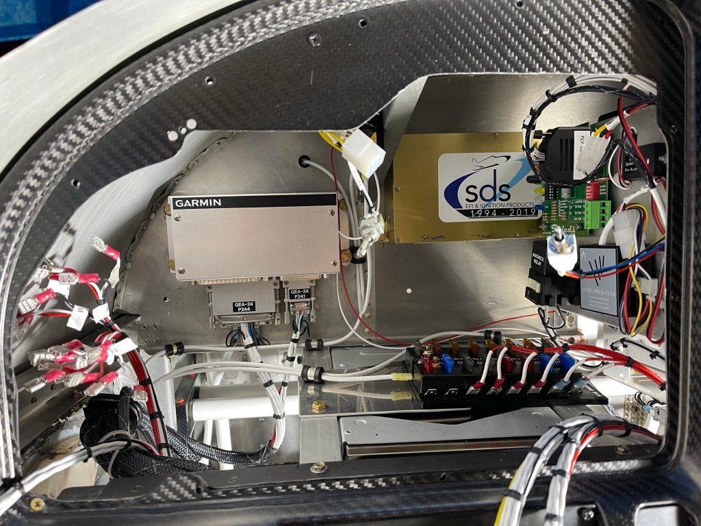
A bunch of time was spent locating the fuse blocks and getting the basic power connections hooked up. Still lots to do, but this is a snapshot of where I am today. Left side, right side, and center of the panel.
Pilots side. Engine bus fuse block is here… mounted on top of the transponder.Co-pilots side. Fuse blocks were the bulk of the work so far on this side. Center part of panel. Not much going on here.. I did wire up my defrost fans..
My panel items don’t contact the sub panel, but the connectors with wire bundles did, so I cut out a rectangle from the sub panel to make sure there was plenty room for the connectors and wiring bundles with strain relief.
Cutting a relief in sub panel
I fabricated a doubler per Van’s plans
Sub panel doubler
Laid out a hole pattern, drilled, and riveted it in place.
Hole pattern drilledDoubler riveted in place
I may end up re-connecting the bottom flanges back together once the location of the connectors are in place. I then fabricated supports of the avionics trays and shelf that houses some components to the sub panel for overall support. I used a small angle riveted to the sub panel and connected another angle to it with a couple of rivets. The aft side where it connects to the avionics trays has a screw with a Nutplates for easy removal if ever needed in the future.
I also took some time to fabricate some hinged access doors to get to the AC connections under the rear seats in the first bay. These will secure down using the 2 existing screw locations on the rib. These connections are for the AC condenser.
Access door in rear seat panA view of the access to the AC connection on bottom skin
Additional work was started on the AC evaporator unit. First up was to mount the return air ducts.
Right return ductBoth ducts on and interior holes cutCap put on
I’m adding a 3″ blower fan to boost airflow into the overhead.
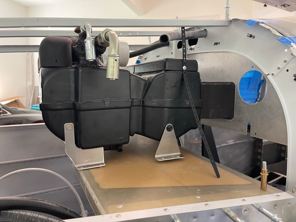
I then placed the flat upper panel from Airflow into position and started rough fitting the evaporator in place on the shelf.
You can see that I will need spacers on the front mounts. I’ve seen several others have to do the same thing. Also I ran into a clearance issue with the J stiffener on the top as shown below. Bill from Airflow said he’s had others run into the same thing due to variation in the units from his suppliers. He’s sending me shorter return ducts to move the unit 2″ forward to solve the clearance issue.
Clearance issue with expansion valveManifold is very close as well, but some gap is present
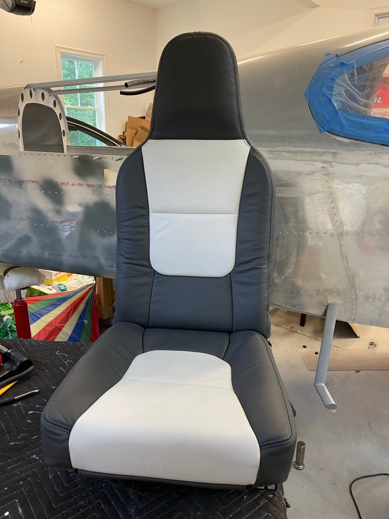
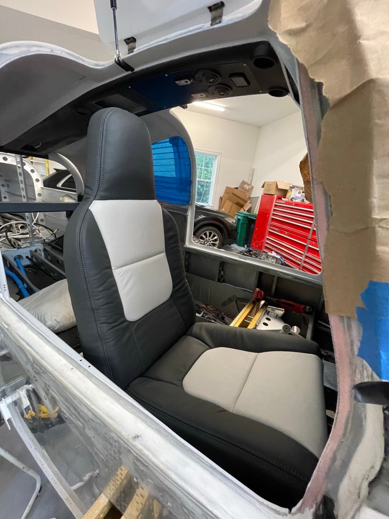
Just before Oshkosh, my seats from Aerosport Products arrived. They came out great! I had to place one into the plane in rough position to see what they look like.
While waiting for AC parts to arrive and needing to finish up some things in the rear of the plane prior to putting the evaporator in place more permanently, I decided I needed to finish some remaining tasks out in the tailcone.
I installed my ELT unit and wired things up to the panel.
ELT in place
I also worked on plumbing my static line from rear to front. This thing needs to go multiple places, so I’ll likely be using a manifold style connector behind the panel vs a long daisy chain.
Static port routing out back.
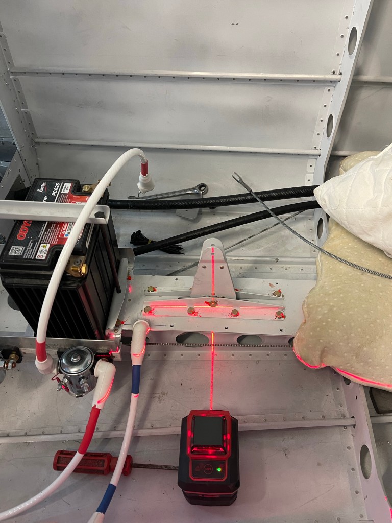
Pitch and Yaw servo installation was next. I used a laser level to help drill the hole needed for the pitch trim arm to connect to.
Prep for drilling pitch trim holein bell crank
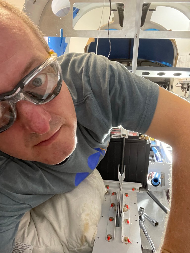
Crawling into a small and uncomfortable space is always painful. Here I am in the back sort of on my side to drill out 4 rivets so I can attach the yaw bracket to the airframe.. Wish I had waited to buck these 4 rivets, but got them drilled out.
Fun in the tailcone. Pitch and Yaw servo brackets in placePitch and Yaw servos in place
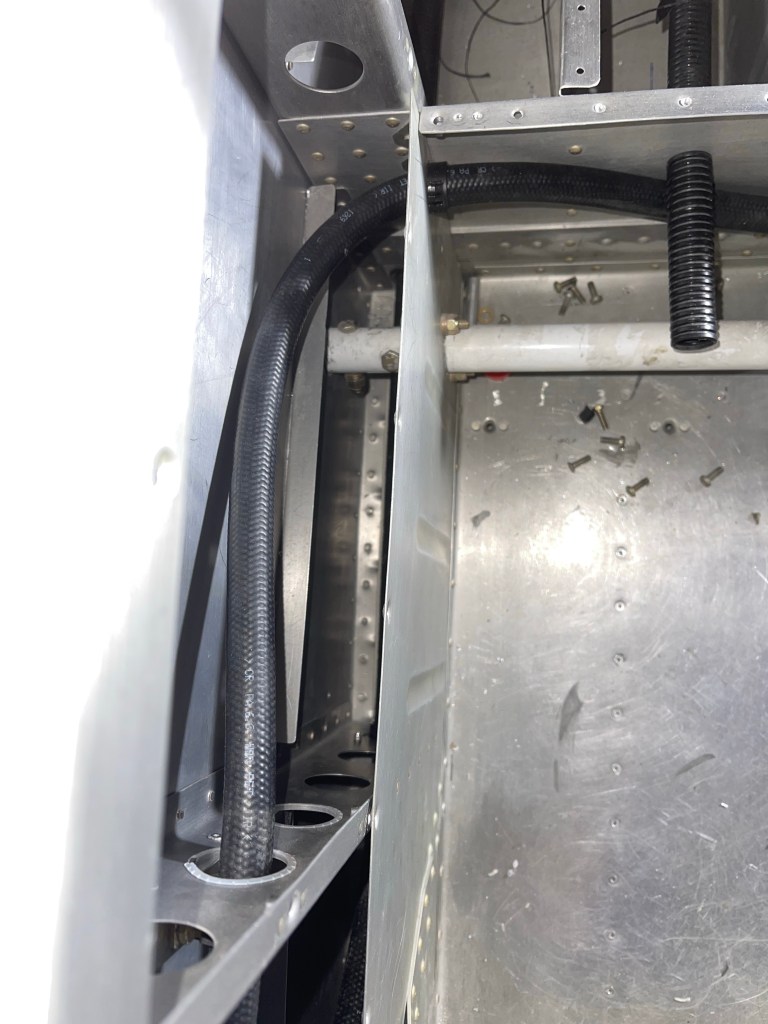
I finished up the routing of the AC hoses down the right side of the fuselage. The hose going all the way to the tailcone dives down towards the floor and goes through the bottom most lightning hole to make sure it doesn’t interfere with the flap tube in the next bay aft. I placed a small piece of angle on the angle attached to the side skin, used nut plates to screw the 2 angles together and then utilized a nut plate to keep the hose from rubbing on the angle attached to the skin.
View of the metal piece riveted in all 4 corners of the lowest lighting hole with a bushing through the center for the hose to pass through.
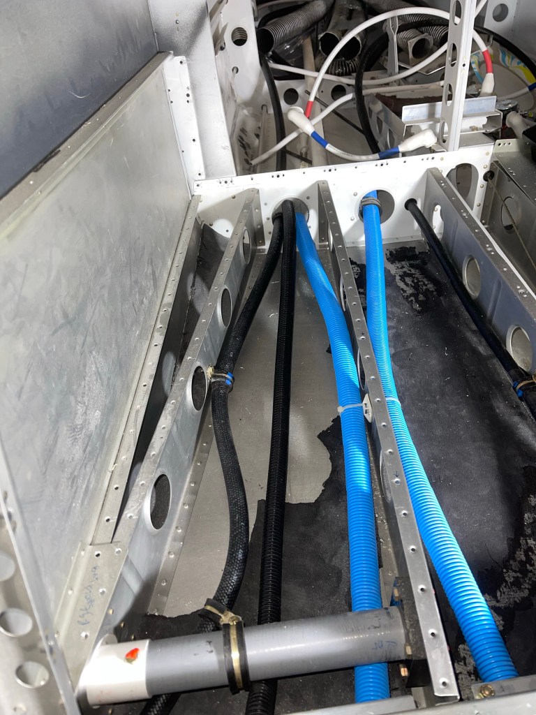
The hose destined for the condenser scoop, goes across the flap tube area on it’s way across the tunnel and to the 1st bay under the left-most rear seat.
Hose continuing to the tailcone under the right rear seat.
I utilized Adel clamps anchored to the step to route the hose inward and keep it away from the bolt holding the step in place. It then makes its way aft to the tailcone.
Similar for the hose going from the condenser to the tailcone.
With the hoses done short of crimping on the ends, I started working on the evaporator shelf by using cardboard as a template.
I test fit the cardboard until it was trimmed correctly to sit between the longerons.
I then used the cardboard to mark up the fiberglass shelf and trimmed it, sanding a little bit to get a good fit. Shown here as well are the 3 holes matched drilled into the shelf brackets that get riveted to the longerons.
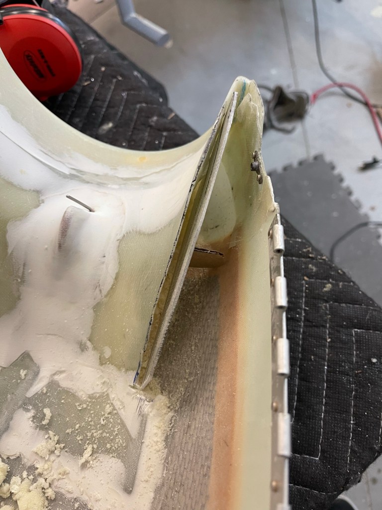
One other small task was to trim the upper cowl ramps and add a “wall” so that the baffle material could sit in-between the upper air ramp and this “wall” so it has something to push against.
Using some scrap fiberglass to trim up a “wall”
I then mixed up some flox and bonded the “wall” in place with a small “D” shaped piece to provide support against the cowl wall. This was repeated for the other side.
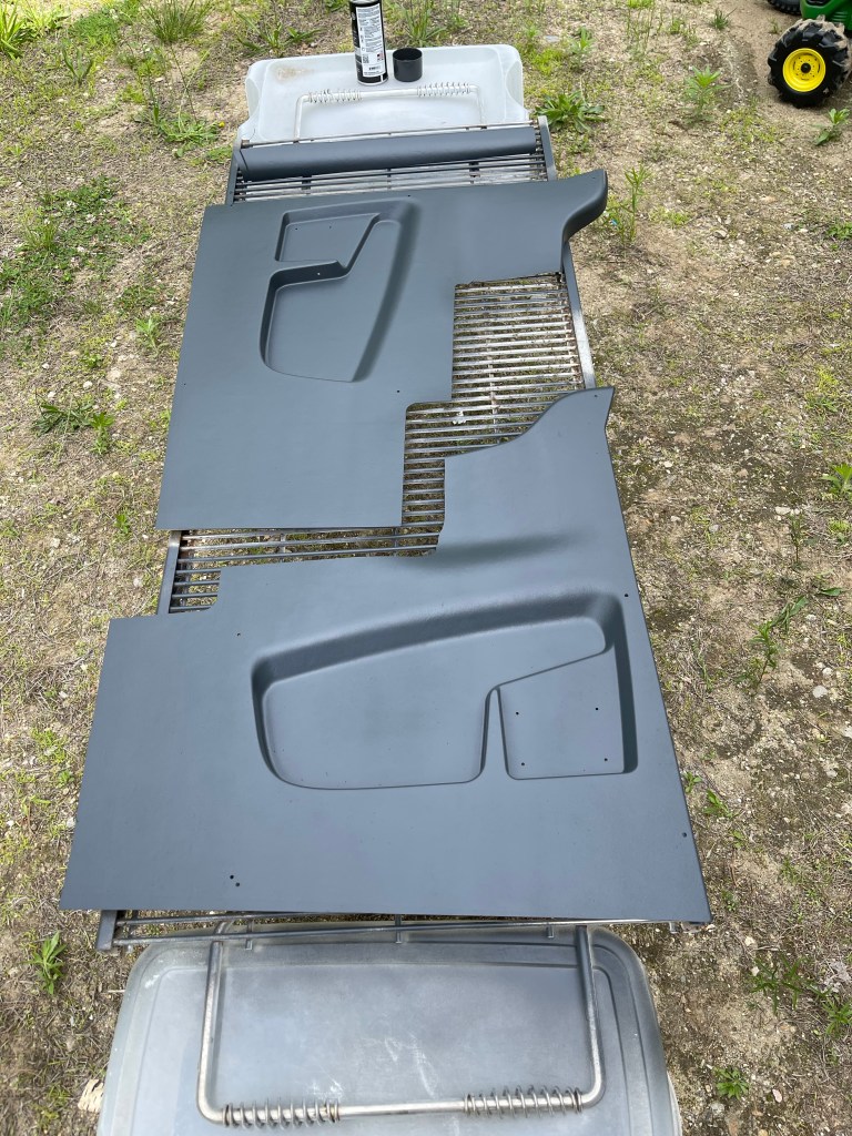
One nice day, I decided to head outside and paint the interior panels. I ordered the lighter tan ones knowing that I was going to paint them a darker color. I think they came out nice!
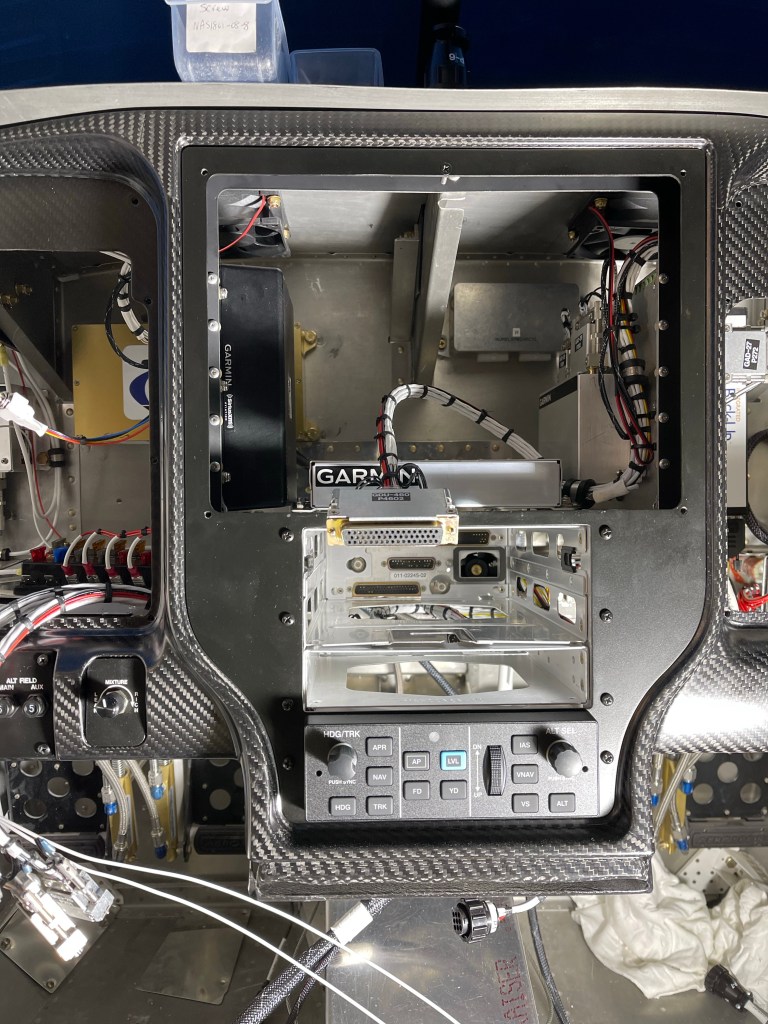
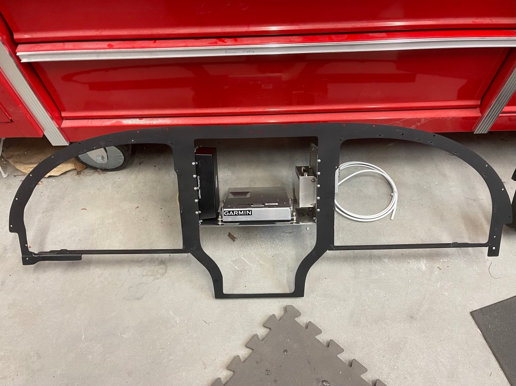
I ran into a snag with continuing with the evaporator install so I worked on completing disassembling the panel. I removed the wiring harness and separated the metal sub frame of the panel from the carbon fiber.
Wiring Harness removedCarbon fiber panelwith avionics trays. Metal subframe with shelf for various components.
I spent some time getting the metal subframe in place, followed by the carbon fiber panel with the avionics trays. This first test fit was mostly done to mark the sub panel where I’ll need to cut away and reinforce making room for the connectors on the back of the 650 etc.. Not a whole lot needs to be removed just a small rectangle near the bottom and really just for the connectors and so the wiring harness doesn’t get bent too much.
It’s really exiting to have the last major piece of the puzzle in hand.. There is still so much to finish up…, but it’s encouraging and helps me to keep grinding away towards completion.
To recap the configuration:
Triple Garmin 3GX touch screens
GTN650 IFR Navigator
Dual GSU25 ADAHRS
G5 Backup Attitude Indicator
GMC507 Autopilot Head
GMA245 Audio Panel
GEA24 EIS (Engine monitoring)
GTR20 Remote COM (COM2)
GTX45 Remote Transponder
SDS EFII Controller
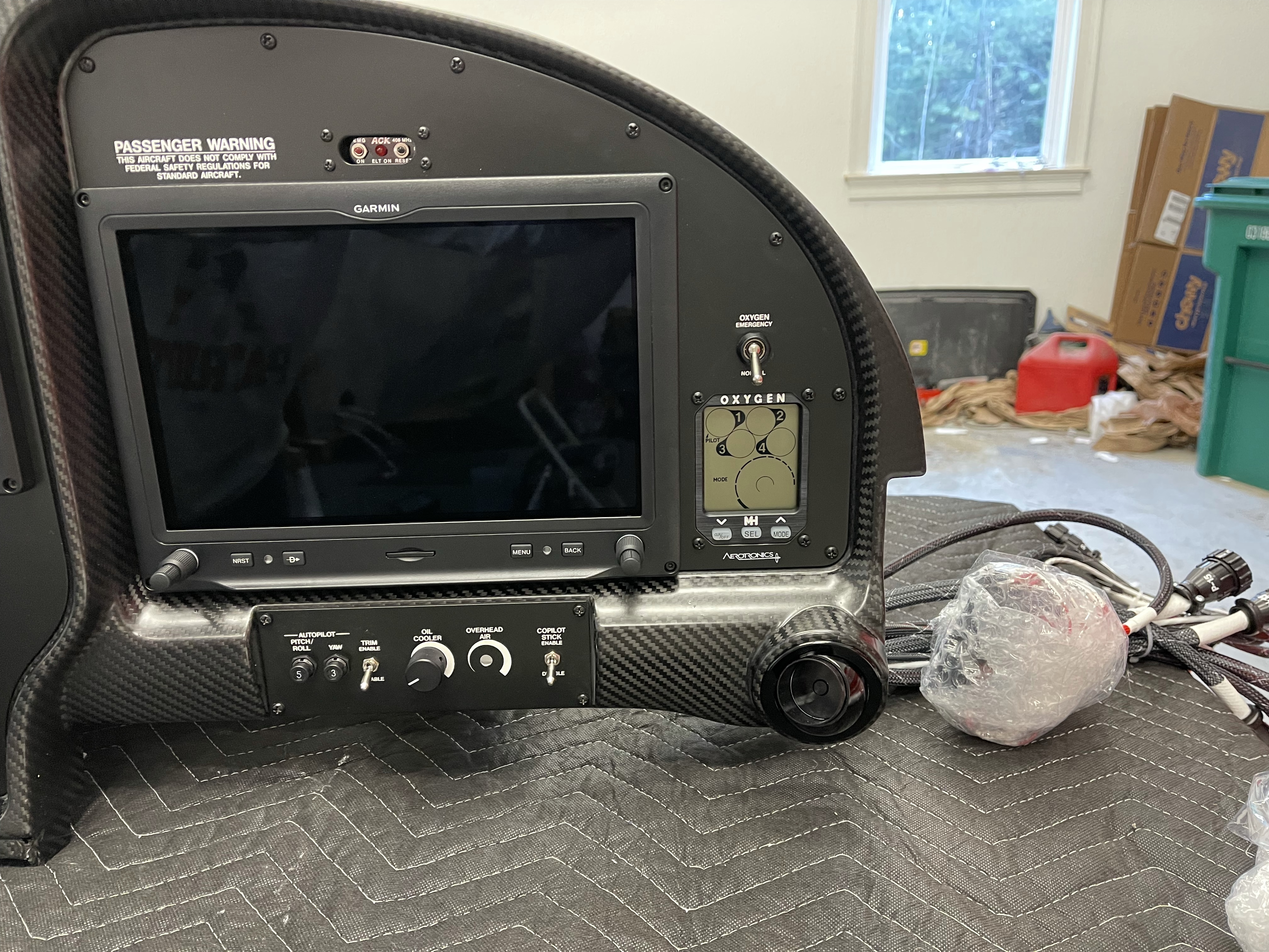
Mountain High EDS-4ip 4 place oxygen controller.
GDL-51R Remote Sirius XM receiver
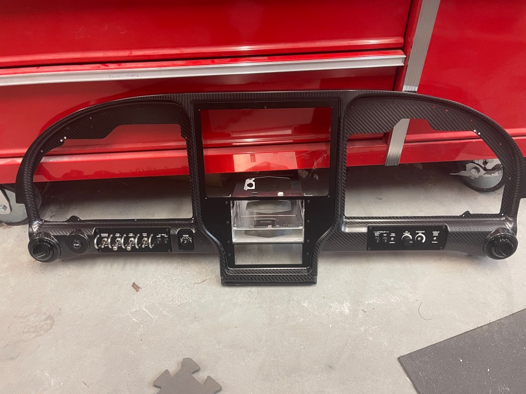
A picture of the panel propped up on my table.
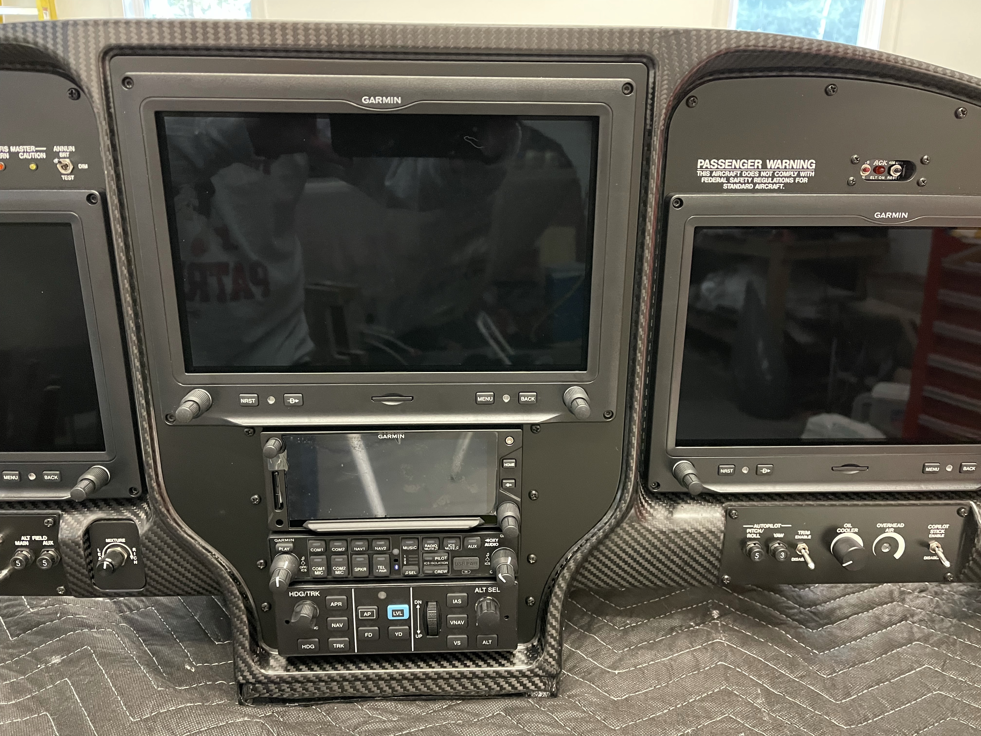
Pictures of the left, center, and right sections closer up.
Aerosport Switch Pod housing lighting controls.
Lower center console housing the SDS EFII controller, defrost, and Air Conditioning controls.
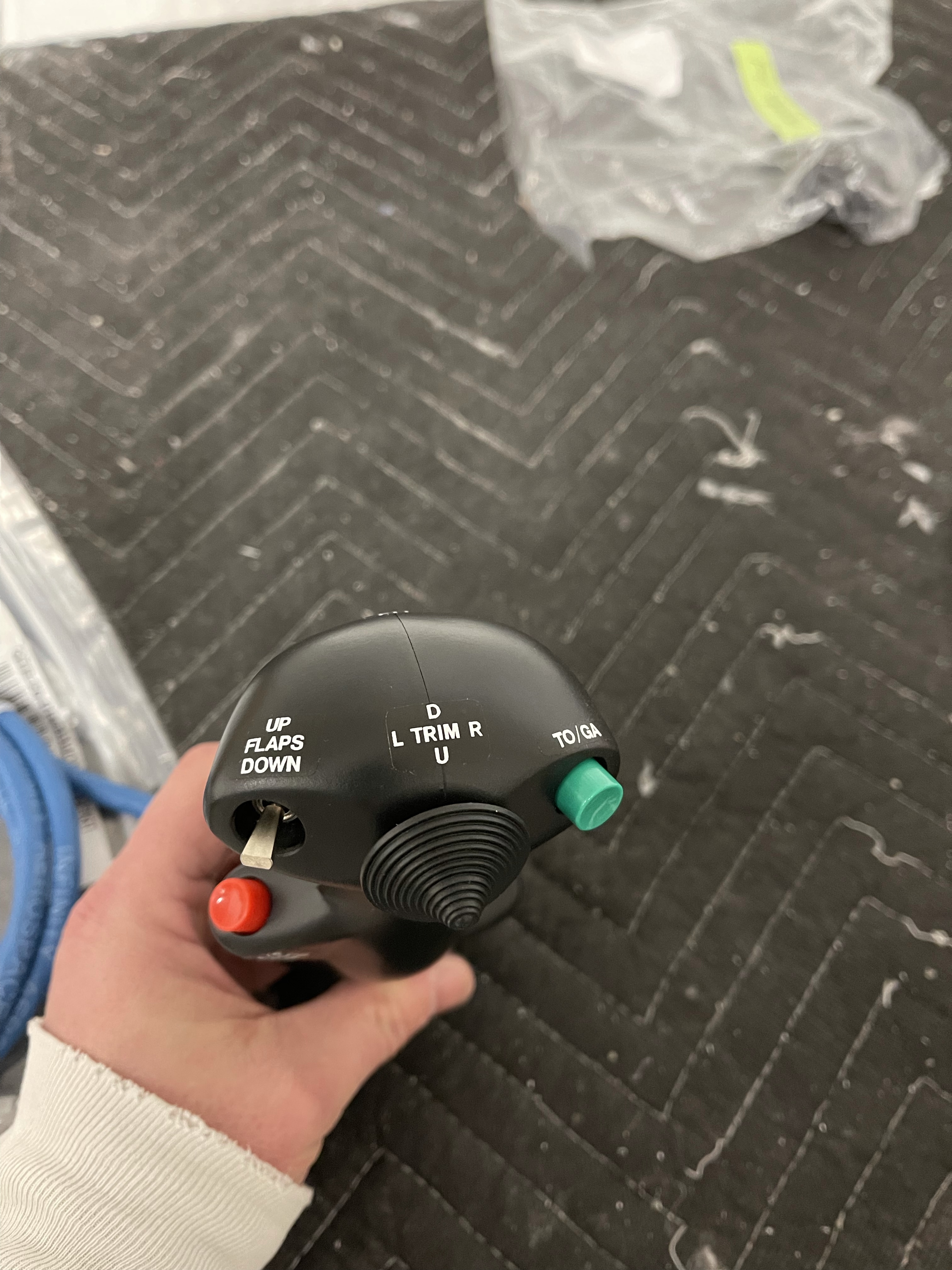
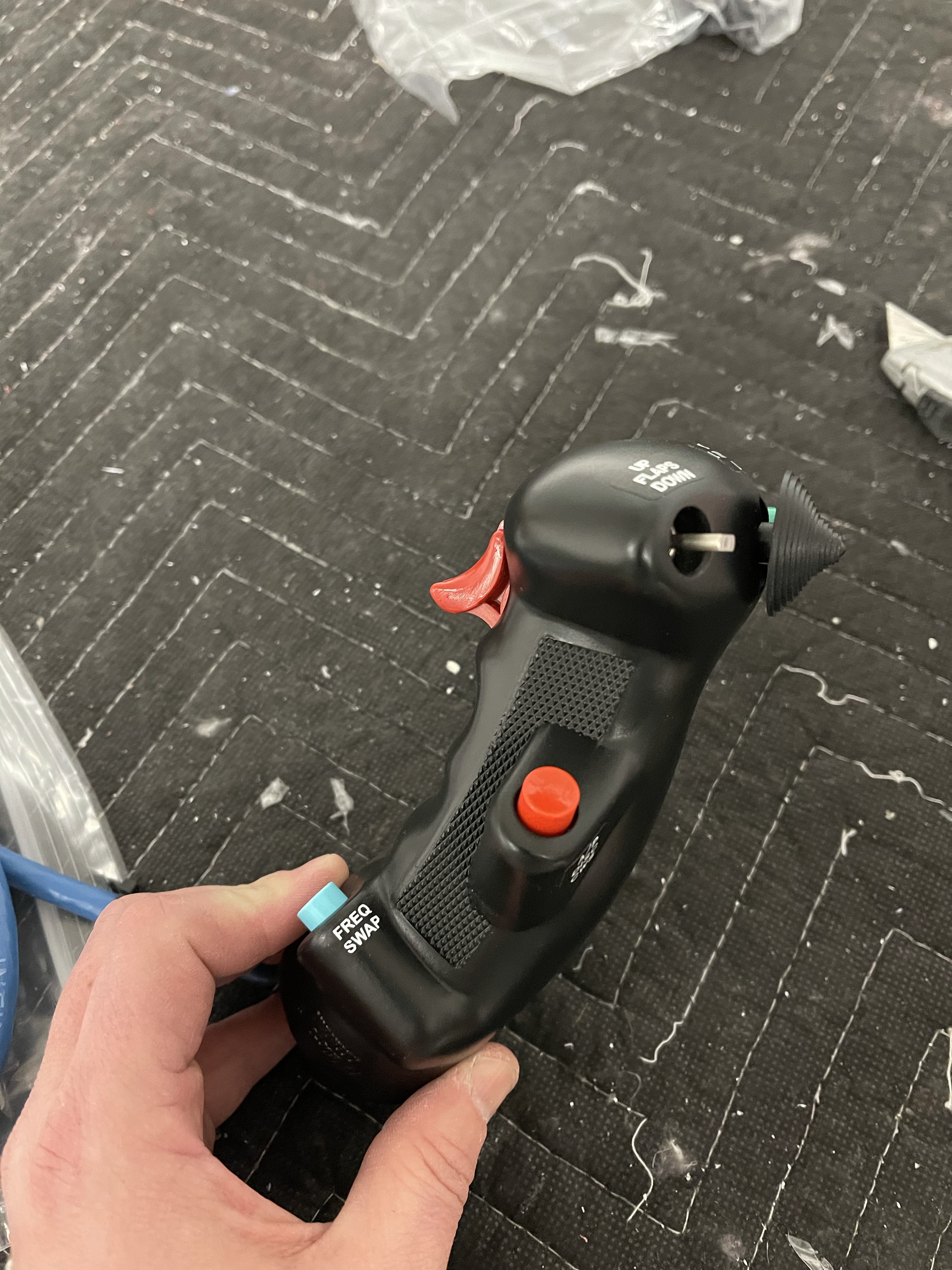
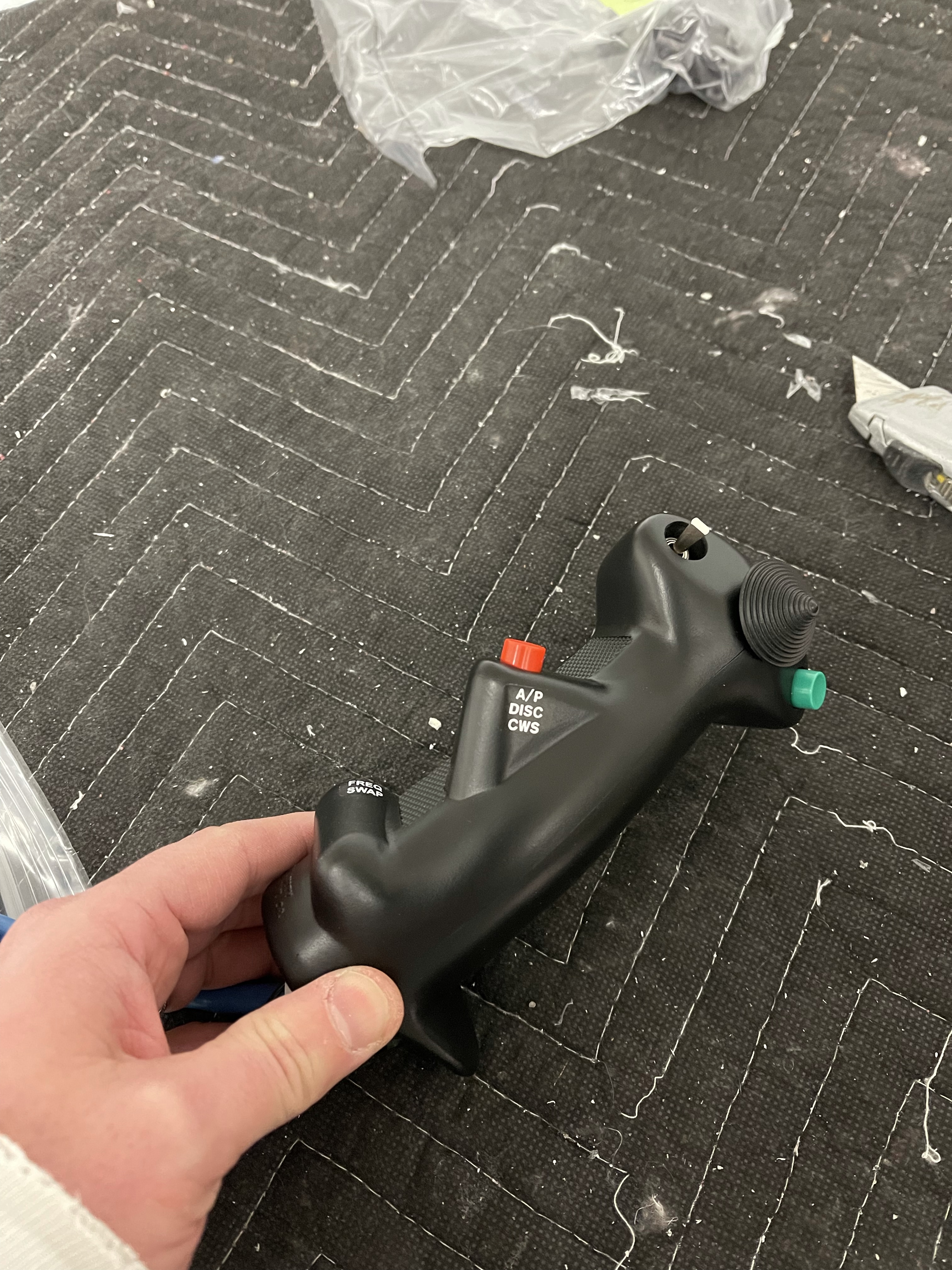
Stick grips came in the package as well all wired up and ready for me to connect. I went with the Infinity HOS (Hands on Stick) Military style grips. Several controls are on the stick that might otherwise be on the panel. The idea here is to have both hands on the controls and throttle during critical phases of flight; not having to move them to activate flaps, for instance.
Here’s a rundown of the button assignment:
High hat in the center to control roll and pitch trim.
A switch on the thumb side to control the flaps. This is a momentary down to advance the flaps electronically to the next “notch” and a constant up position so the flaps are raised all the way up.
Opposite of the flap control, there is a Take off/Go Around button. This will sequence the autopilot/GPS to the missed approach segment when needed.
The Red button on the thumb side is a Auto pilot disconnect/control wheel steering button.
And finally a frequency flip-flop button. I didn’t really know what to add to this button, but decided on this.. Some people do ident, start button, or other functions. We’ll see how useful this ends up being in practice.. Guess if doing instrument approaches etc.. I may be setting up next frequencies in the standby area ahead of time enough to just have to hit a button with my pinkie to switch when needed.. We’ll see..
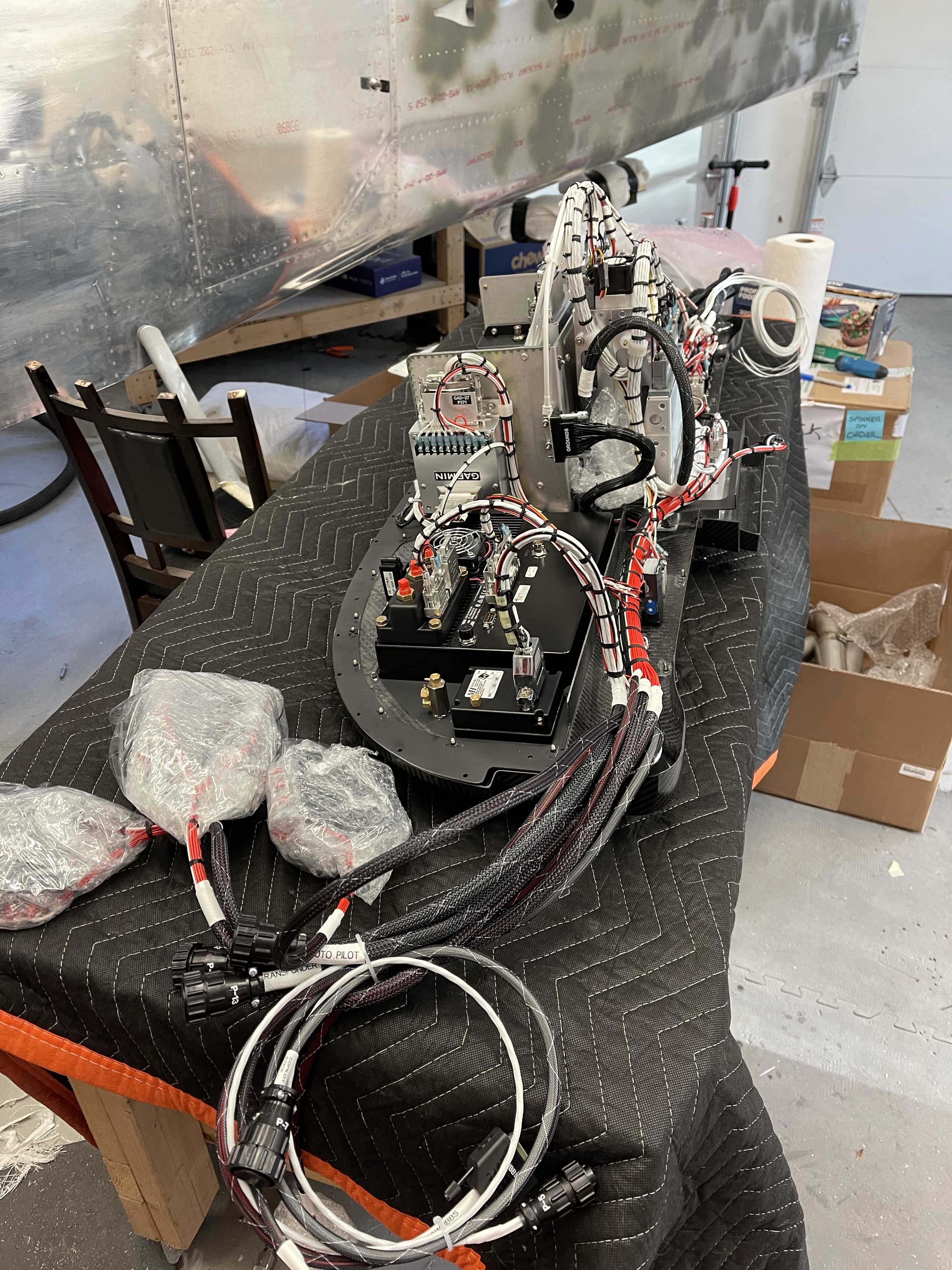
And finally some pictures of all the wiring between all the components. Along with several P-Plug connectors on either side of the panel for me to connect to all the other locations in the plane. Aerotronics mounts as many of the sub components right to the panel, as you can see. This alleviates me from having to mount them on my sub panel. Of course all the wiring harnesses are also already all done for me. Including runs out to the wings for AP servos and magnetometer, along with runs to the back for AP servos and trim servos back there. Lots and lots of wiring ahead..
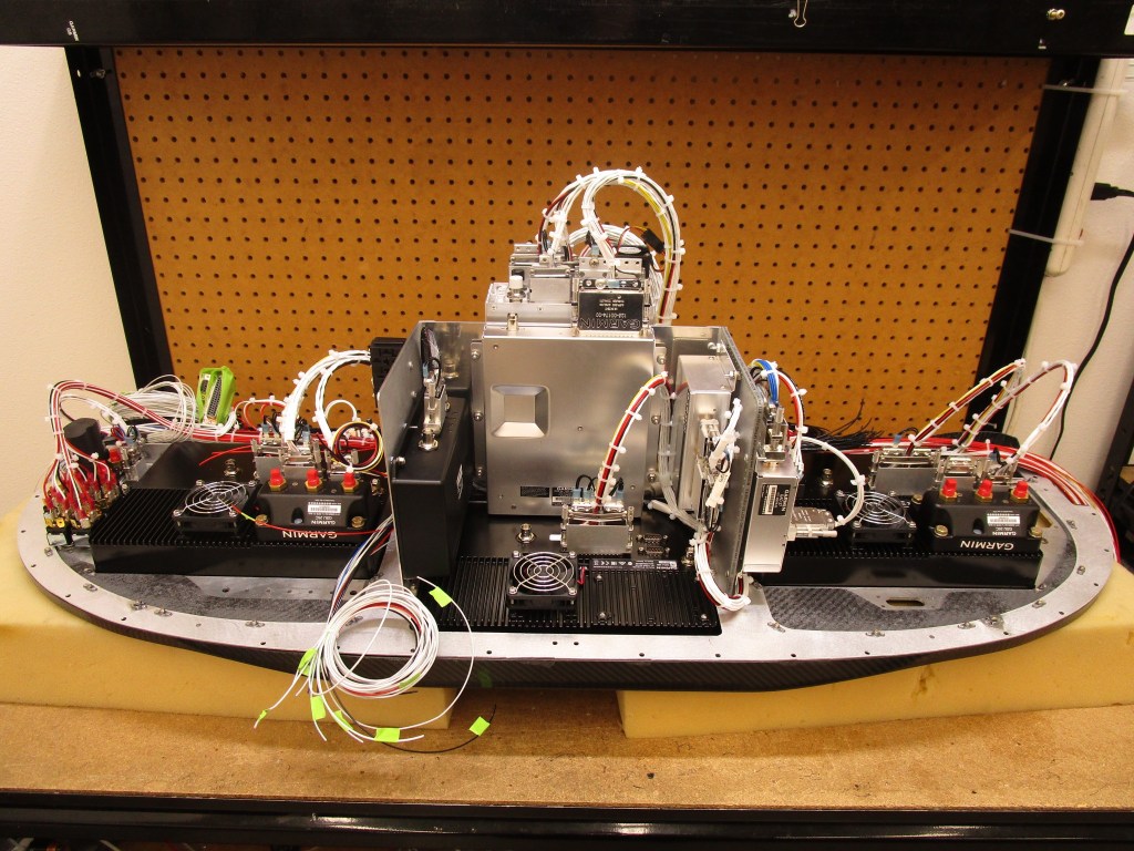
And finally a picture of my panel from Aerotronics all powered up and tested prior to shipment.
Just a quick update with some additional pics of the backside of my panel in progress at Aerotronics.
Probably a couple more weeks before it’s ready to ship.
Closeup of the G5 and switches above.Note the switch pod up high A nice closeup of the shelves that house most of the subcomponents including the FlyLED controller.
Just a short post to show some progress on my panel build at Aerotronics. These were sent at the end of October. I should be taking delivery towards the end of December.