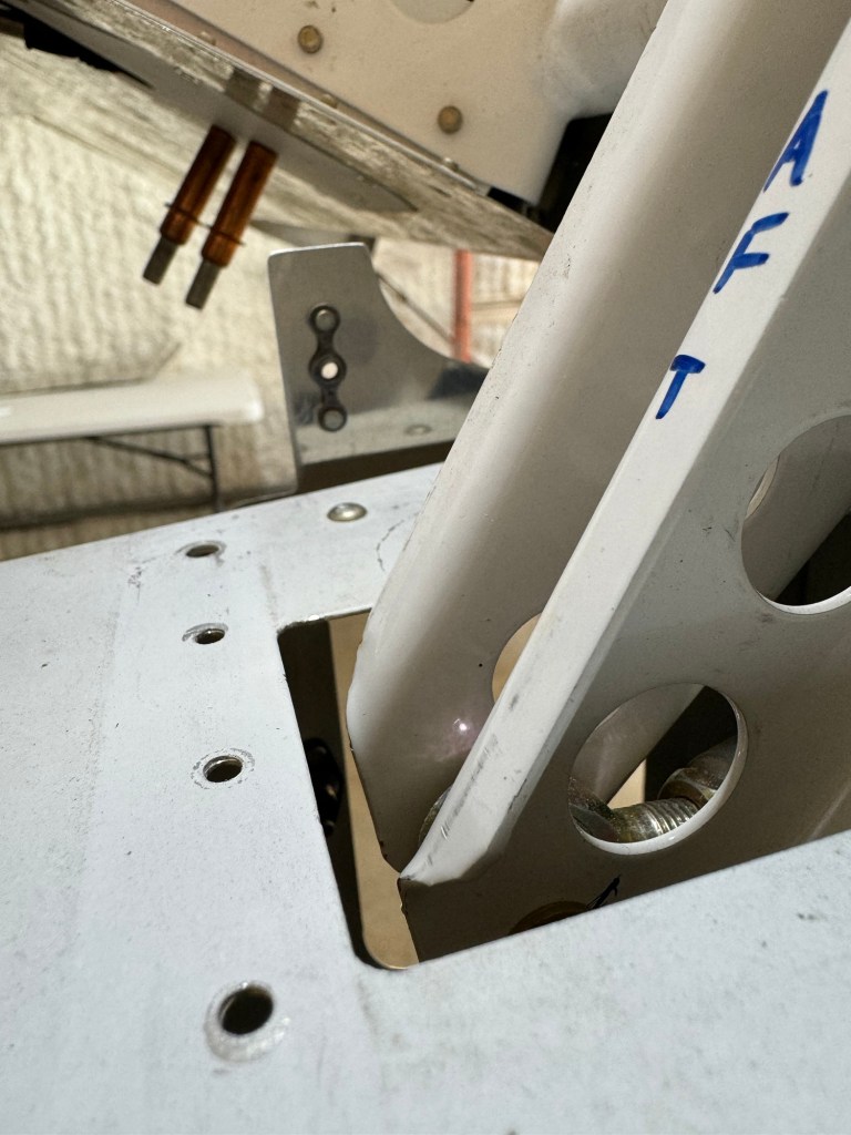
I test fit the fuel supply and return lines in the wing roots. Everything looked good once I clocked the sidewall bulkhead fitting downward a bit. I plan to put some tubing on the fuel line to avoid abrading the spar and side skins.
Left side before return line clocking. Looking at the supply shutoff/filter setup. Looking up on the whole supply line/filterRight side after clocking
I then went down the road of finalizing my rigging. Everything went well except for my elevator rigging, which was somewhat expected. I was fighting a couple of different things. The first was that my stick hits the switches on the Aerosport panel, like so many before me. Some end up bending their stick to get more clearance. I decided to solve it by adjusting the forward and aft stops as well as changing the aft rod end of the forward (F-1089) pushrod from a MD3614M to a MD3616M to get more thread length to allow me to unscrew it more, resulting in the stick not going as far forward, while still having enough thread engaged in the pushrod.
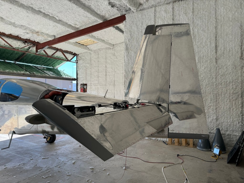
Additionally, I was very close to needing to do the elevator stop service bulletin. So I took the opportunity to do that as well. To do these changes, I needed to take the rudder and Vertical Stab off to get better access.
Unbolting and unriveting the original aft elevator stop. Stop completely off Showing the elevator horn angle and how close it is to being able to jam on the stop. New aft elevator stop installed to address service bulletin and adjust travel as needed.
I also installed a forward stop as well to help further limit the down stick travel by limiting elevator down travel to the min of 20 degrees.
Horn sitting against new forward stop installed
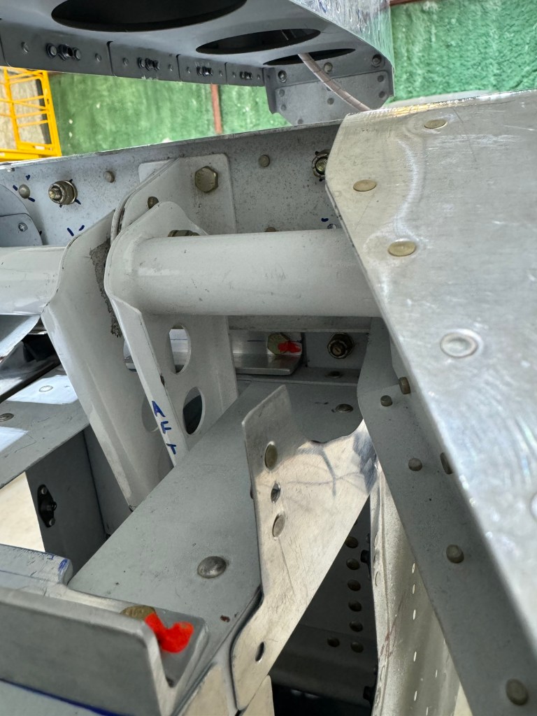
I then battled another issue with the control stick travel and a bolt head hitting the control column mount. This seems to be due to the angle of the stick weldment not being 70 degrees. It is causing the travel in the space cutout for the aileron pushrod to be biased forward as shown below.
Stick aft rod is completely forwardStick forward only 3/4 travel in slot
Van’s tells me that this is usually due to the pushrod lengths being off. So I spent a ton of time removing all 3 of my pushrods and re-checking their lengths. They were really close as they were. Then working on setting things up properly from aft to front. At the end of the day, even with the stock measurements of the pushrods, I still have the same issue, so that is not the root cause.
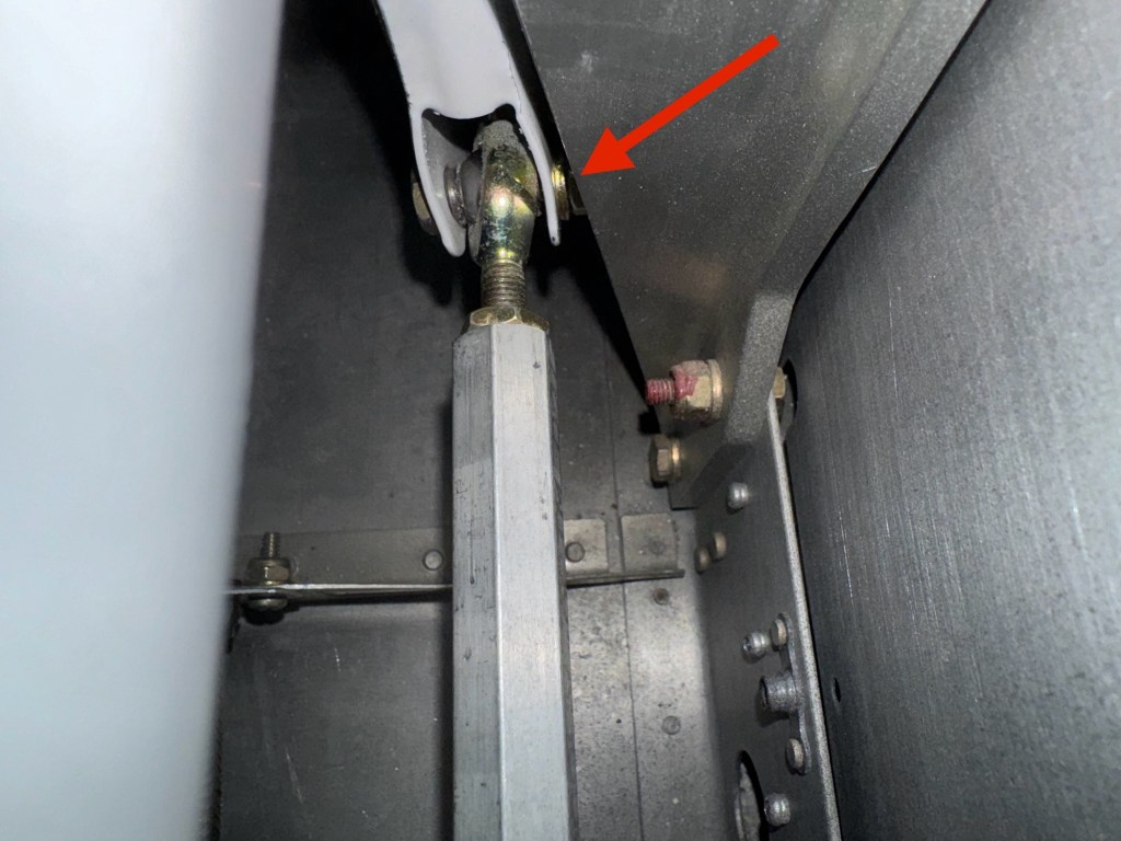
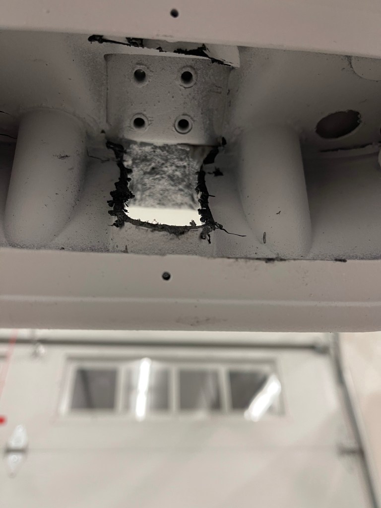
Below I show the interference with the bolt and the mount.
You can see where the bolt was hitting.
So I decided to carve out a half moon as shown above in the mount to create clearance for the bolt. At least one other builder has told me they have seen this a bunch of times and done the same thing.
One other problem that resulted from this forward bias, is that the aileron pushrod that connects the 2 sticks through the tunnel was rubbing on my fuel lines as shown in the video below.
There was no possible way to move the lines forward anymore due to me having a brake line in the way.
In talking with Tom, I asked him to make 2 new lines for me that were 1/2″ longer to solve this issue.
New lines in place and rubbing problem solved.
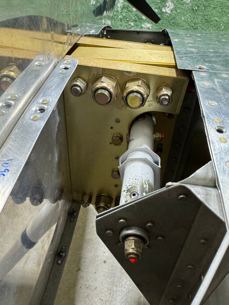
With that saga behind me, I then bolted the wings on permanently. There are 8 bolts holding each wing on.
I also finished wiring the wings. Below is the air temp sensor under the 2nd access panel on the right wing.
Wingtips were also installed and tested out.
Now there are a couple of things left to finish up and then it’s time to get ready for my inspection. Calibrating gauges, fuel tanks, doing fuel flow tests, etc…
Lots of progress since moving to the hangar. It started by getting the tail pieces back on.
I then worked to get the emp fairing cover trimmed and in place and matched drilled to the holes in the metal using a strap duplicator. Then added nutplates so it can be held down with screws.
I needed to double check the nose wheel nut break out force and get a cotter pin installed. I really should drill a hole in the floor to thread a ring into for the strap, but I was able to use some blocks I had lying around and my creeper to pull the tail down, lifting the nose wheel off the ground.
I also spent an inordinate amount of time trying to bleed my brakes. In the end, I had to use a garden sprayer type setup to be able to build up enough pressure to push the hydraulic fluid from the brake caliper all the way up to the cylinder on the firewall. All other methods I tried (oil can, and also a vacuum bleeder from the top) failed to be able do the job.
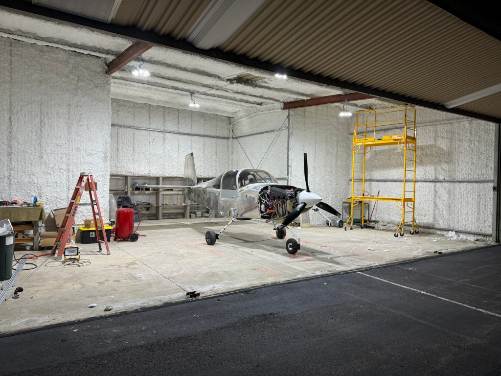
I knew when I got my hangar that the single halogen light was not going to be enough. Still, in order to make progress, I made due with the use of some portable lights in the area(s) I was working. One day the bulb burnt out and rather than replace it, I took it as a sign that I needed to stop and just upgrade the lighting in the hangar. Below is the result of adding some new LED lights.
Once my ZipTips were done at home and before the first snow, I was able to get some help to transport the wings to the airport and subsequently get them onto the airplane!!!
Since getting the wings on, I’ve been able to get the flaps and ailerons on and rigged.
I’m now working on finishing up section 44 which is mostly about wing root fairings, fuel tank vent lines, and connecting the fuel lines between the tanks and the fuselage.
Flap connectedAileron push bar connected.
In testament to the user friendliness of avionics these days, Declan seemed to pick up on how to use the EFIS right away. 🙂
I used some of the soft aluminum tubing to make the vent lines for the tanks as shown below.
So what remains is to finish the wing root fairings and get my fuel lines connected. Then I will need to take the wings off one last time to debur some things and finish some nut plates on the tank. Then I can bolt the wings permanently and finish up the electrical wiring.
After that it is mostly getting ready for first engine start and preparing for inspection.
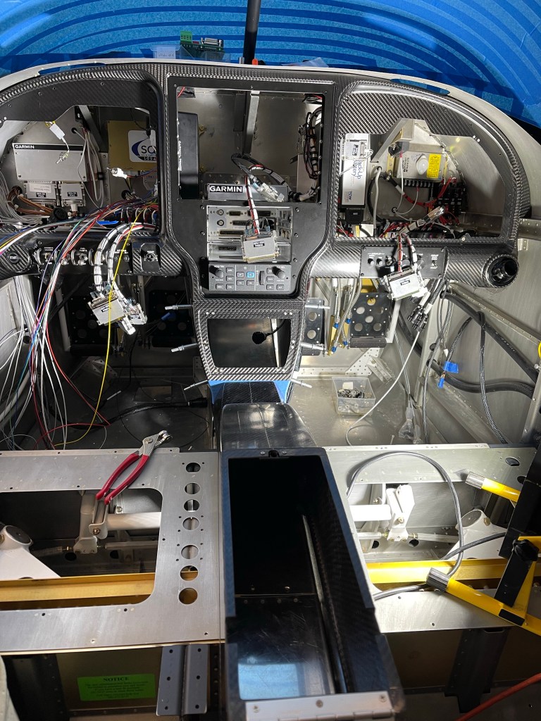
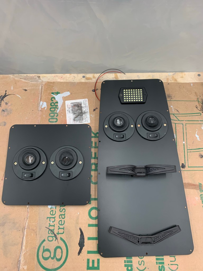
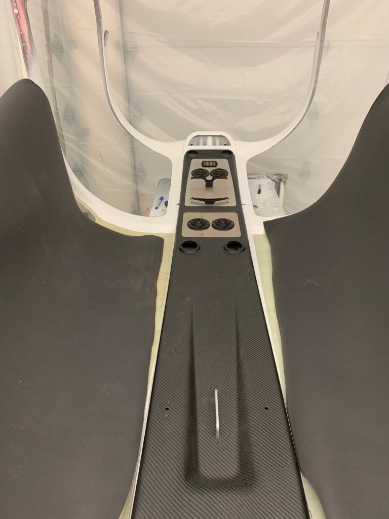
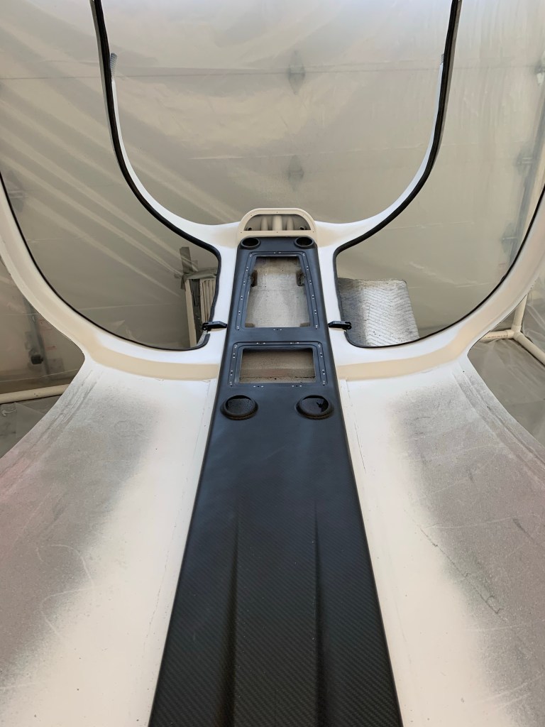
Prior to starting to wire all the FWF stuff, I decided to get my lower console with its side panels and the center armrest with the fuel selector and throttle quadrant installed. The main reason for this, is I need to measure for my throttle and prop cable lengths and I can’t do that with out placing the quadrant.
I first mounted the lower instrument panel console and got it match drilled to the left side panel. The same was done to the right side panel. I used a strap duplicator to match drill holes into the side panels along the top of the tunnel so we can secure them to the existing hole/nutplate locations. Once that was done, I located the center armrest into position and matched drilled 6 holes (3 per side) also to the existing screw holes on the top of the tunnel.
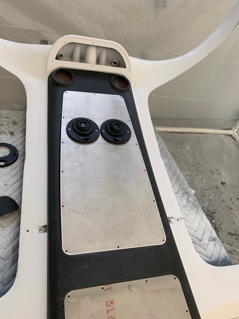
I then cut out the armrest for the throttle quadrant based on the scribe lines. I placed the quadrant into rough position in the armrest while it was upside down and taped it down. I placed masking tape down on the tunnel cover approx. where the quadrant will sit. Then with the center armrest placed down and screwed to the tunnel cover, I marked the legs of the quadrant on the masking tape through the top opening of the armrest. I then removed everything and drilled holes and bolted the quadrant to the tunnel cover. The holes are slotted, so you have some fore/aft as well as up/down adjustment. Getting it pretty close was sufficient. The harder adjustment was the up/down as you don’t have access to the screws with the armrest in place.
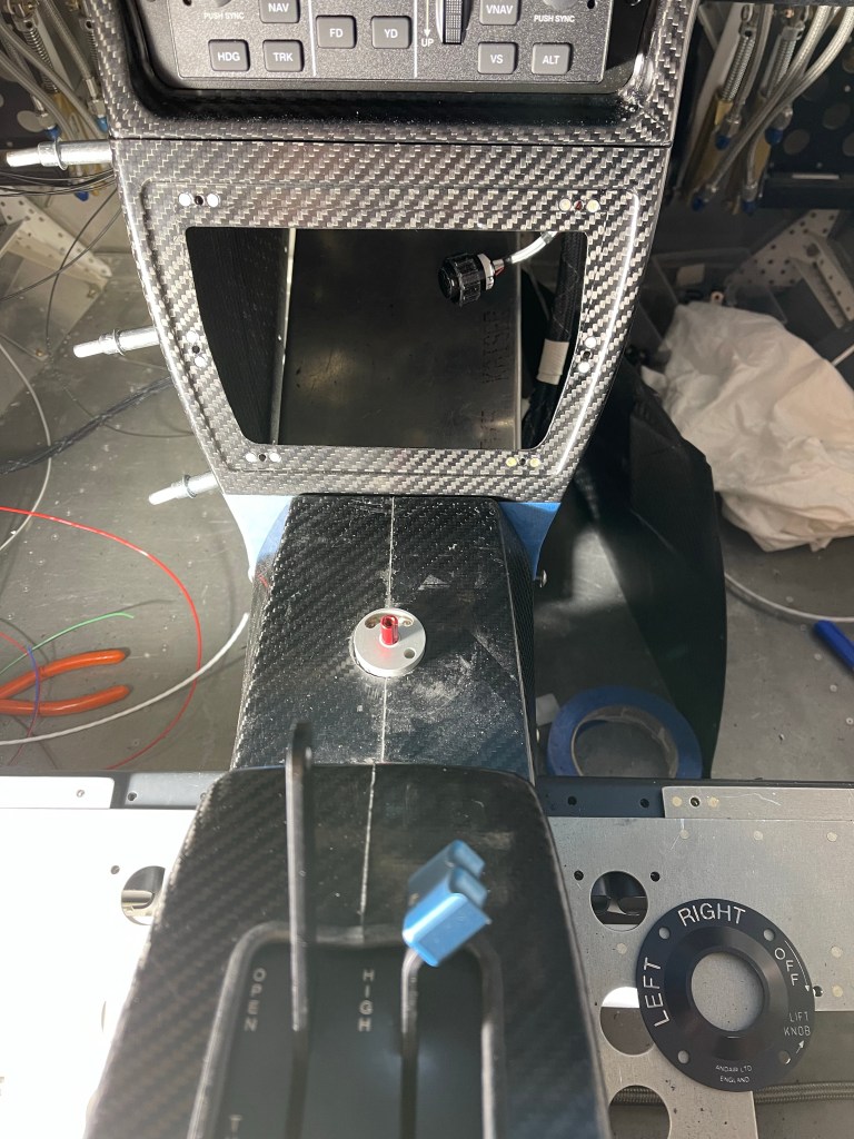
Once that was done, I had previously placed the Andair selector valve more or less in the stock location. So I drilled the hole provided by Van’s up to 3/4″ round hole for the Andair extension arm to come up through the tunnel cover. The extension was pretty close to centered on that hole, so I left it as is.. I used that hole in the tunnel cover to locate and drill the hole in the carbon armrest for the selector.
Throttle quadrant and fuel selector valve hole cut
Then the extension arm was cut to the proper length following the Andair instructions and the bottom part of the selector was placed onto the arm and test fit to the hole in the armrest.
The faceplate was put into position and I used the 4 screw holes on it to drill holes into the armrest. I prefer the orientation to be as shown below. I feel like it’s a little more clear this way as the selector will be pointing left and right for selecting the respective tank. Mounting the faceplate so that the “Lift knob” is right reading, so to speak, would have left tank selection pointing really left and right tank selection still pointing left, just not as much.
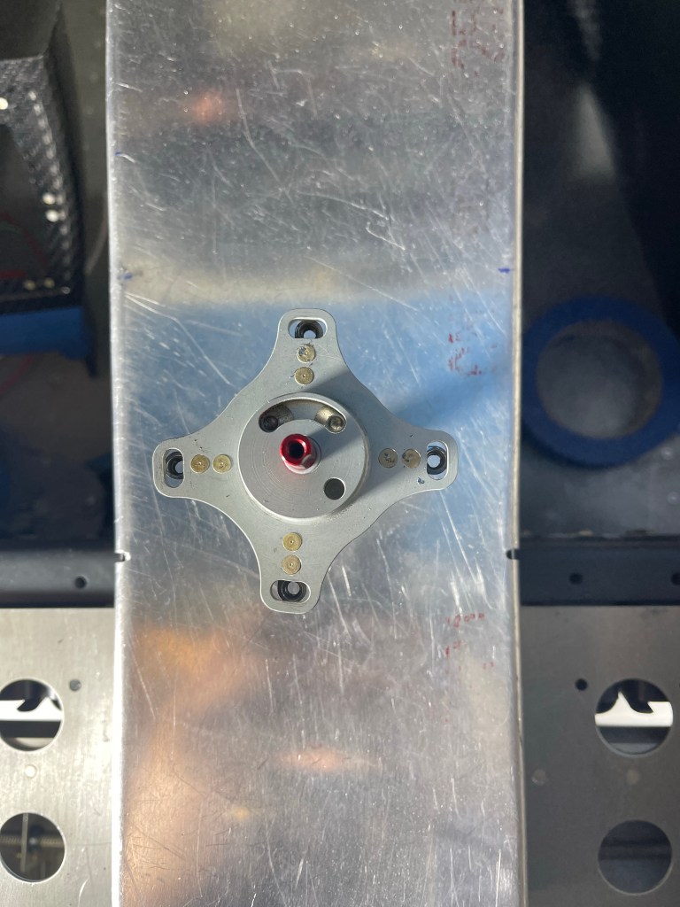
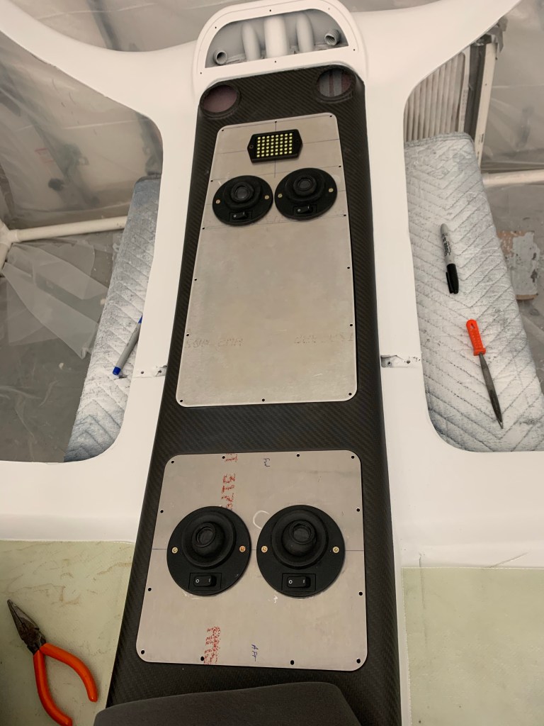
In order to be able to potentially remove the center armrest without removing the lower console nor the fuel selector valve, I used nutplates on the piece that sits under the selector valve as shown below. A couple of the holes on the armrest has to be oblonged a little bit to make the screws meet the nutplates properly, but that isn’t a big deal as the faceplate covers that area.
Nutplates on face plate screwdown plate
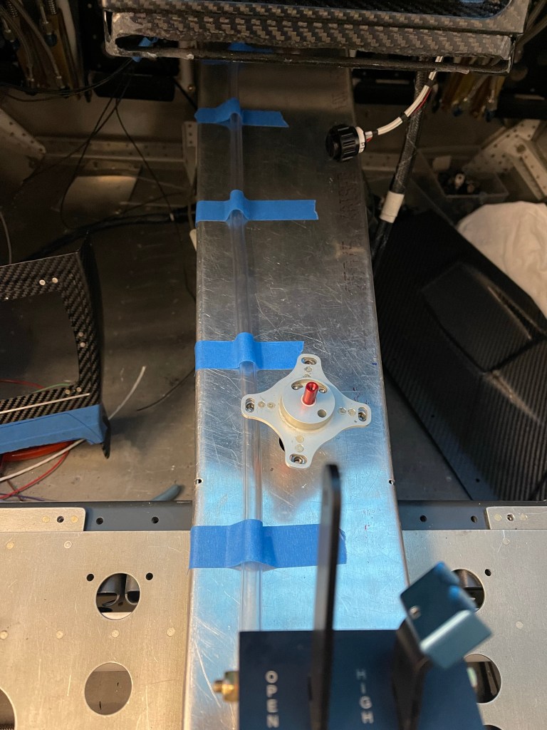
With all that done, below are the end result at various angles.
I was then able to measure for my cable lengths. I used some vinyl tubing I had lying around to emulate the route for both the throttle and prop cables. I marked around the mid point of the threaded part of the bearing/tie rod terminals and made sure the controls were both full deflection in the same direction (fwd/fwd or aft/aft), I then pulled the tubing out and measured the marks. I did add a couple of inches for some slop or slight variations in the install path that I measured to.
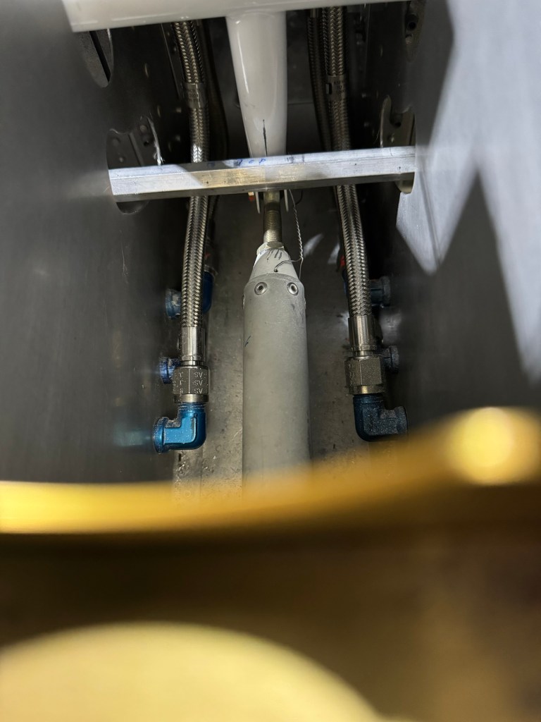
Back when I installed my fuel lines, Tom from AS Flightlines ( http://www.aircraftspecialty.com) really only had one solution to the SDS fuel filters. On top of the fuel pump module using adel clamps. I really don’t like having these in the tunnel for maintenance reasons. It seems inevitable that some amount of fuel will spill out into the tunnel no matter how careful I am trying to catch it all as I take this all apart for yearly service. Additionally, I placed the access panels on the tunnel sidewalls a little further aft and not perfectly aligned to the whole assembly, so access to the forward-most fittings is a bit challenging. Taking the top of the tunnel off, while doable, is a royal pain seeing there are throttle cables, etc.. routed on top of that. I really have always viewed this solution as something I’m going to regret and will spend way more time than I really should on each condition inspection. Also I can envision lots of curse words being used. Below is a view of the original filter setup in the tunnel.
Original tunnel fuel filter arrangement.
Since that time, Tom has come up with pre-filters in the wing roots, and moving the post filter firewall forward. Despite having some re-do.. I opted to take some time now to change and use this new configuration. Maintenance will be much easier and more accessible that way. If fuel does spill, it’ll be outside of the cabin. With just the fuel pump in the tunnel, there will be basically no reason to ever go in there very often at all, other than to remove the access panels and check on the pumps.
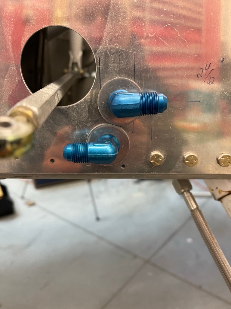
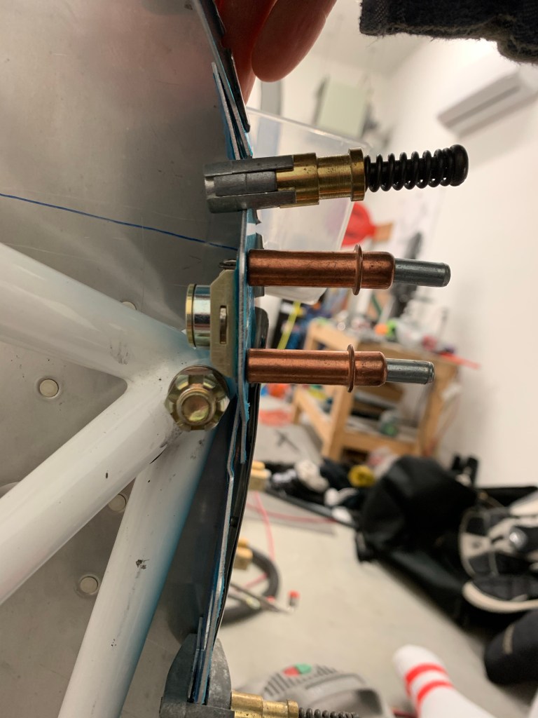
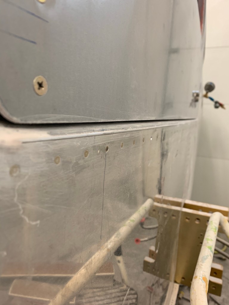
Of course that meant all new cabin hoses and some additional expense, but Tom actually helped out in this regard. I also went with some other arrangements that Tom has standardized on for routing, like having the supply come out on the left side of the firewall and return on the right. One thing that we did decide on was seeing we had to remake the hoses under my seats, was to re-use the hole I had already cut for one of the fuel lines. I cut this hole pretty close to the stock supply hose location and sided it just big enough to get a -6 hose swivel fitting through. Seeing both the stock and hole I drilled were too big for normal AN bulkhead fittings, I had to utilize the TCW fittings (https://www.tcwtech.com). Bob has come up with a washer with a neck/bushing on the inside that fits into the 1″ stock location so the fitting doesn’t fall through the hole. I also asked Bob if he could make me a custom one for the 25/32″ hole that I had already drilled. He made it the next day and had it off to me. I’d say I had a bit of shit luck with how these 2 washers fit basically perfectly. I really figured I was going to have to carve a half moon in one of them for clearance to the other.
Supply and return fittings on the fuselage side skin.
I installed 2 new hoses under each seat for the supply and return.
Below you can see the routing to the side skins. In retrospect, I really wish I didn’t route my brake line in the middle row of the systems brackets.. It would minimize hose crossovers.. In the end the right-most hose in the picture below passes under the brake hose with some clearance. The left-most hose is angled enough with the 45* fitting that it also clears everything.
Routing of hose lines to side skin.
I then spent some time re-locating the pump module. I used the “standard” length hoses from Tom to place this. I also noticed that I needed to raise the module up 2″ from the 3/4″x3/4″ angle I had placed on the tunnel sidewalls already.
Using the hose lengths to place the pump module.
In order to raise the module up, I decided on using some square aluminum tubing. I could some 2″x2″x.125″ material on Aircraft Spruce and ended up cutting 2 pieces. I re-used one set of holes and nut plates I already had on the angle for the aft-most tube. I then added 2 new pieces of angle for the forward tube as shown below.
Using square tubing to elevate the pump module 2″
I was then able to bolt the pump module down with 4 bolts into the square tubing with nut plates and AN3 bolts. I added a couple of adel clamps to the longer return hose as it made its way back to the selector valve.
Finalized pump module
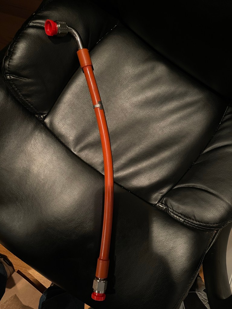
Tom also sent along my FWF package with integral firesleeved hoses.
Example of the integral fire sleeve hose
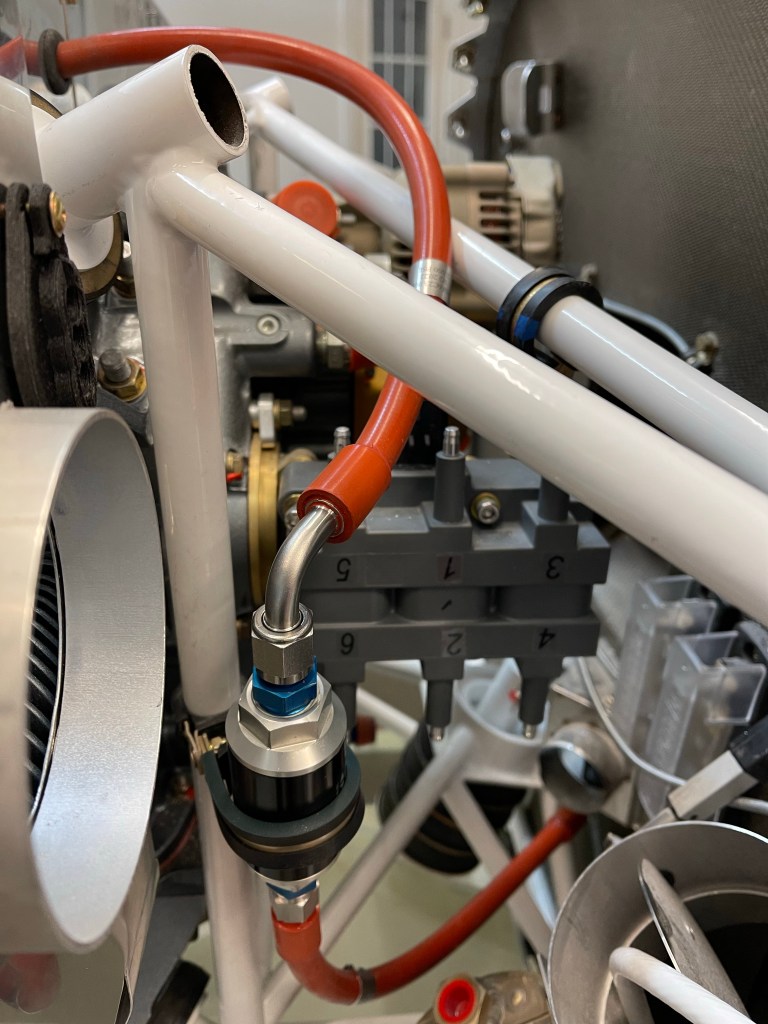
I started on the fuel supply and routing it from the firewall to the post-filter to the fuel block on the top of the engine. This hose passes through the aft baffle with a grommet.
FW to post filter hose. Post filter location on engine mount vertical tube and routing through baffle Supply hose to fuel supply rail on engine top. The T fitting is for fuel pressure back to the manifold block on the firewall.
More FWF plumbing to come now that the cabin and pump are complete.
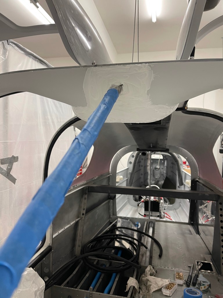
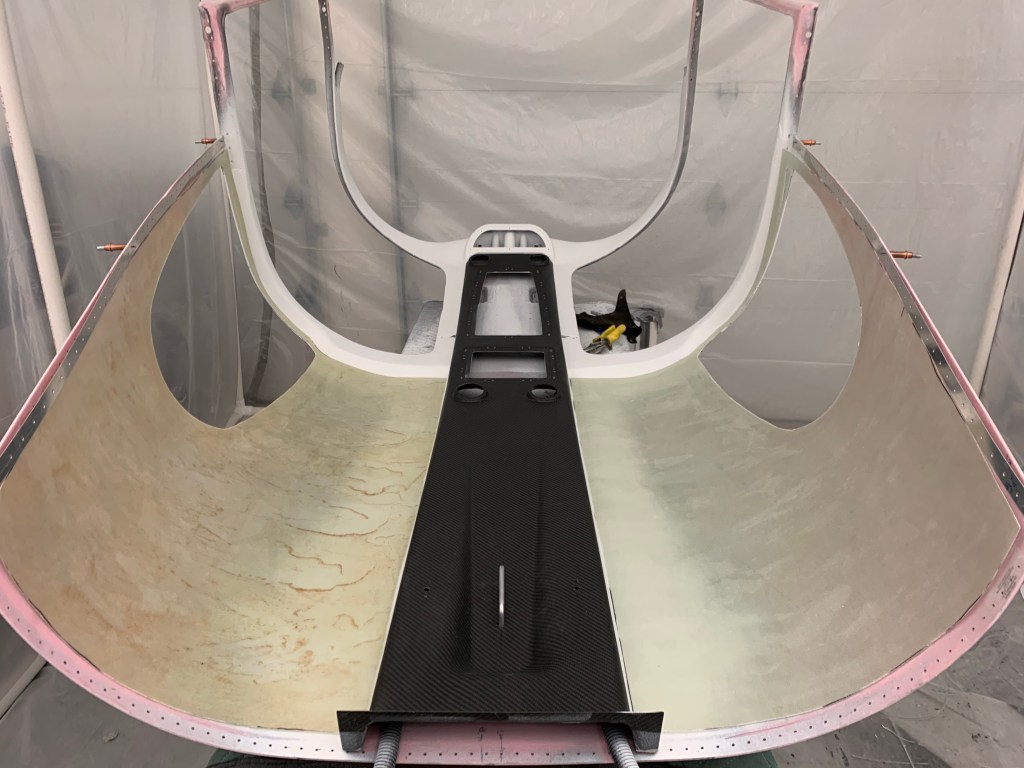
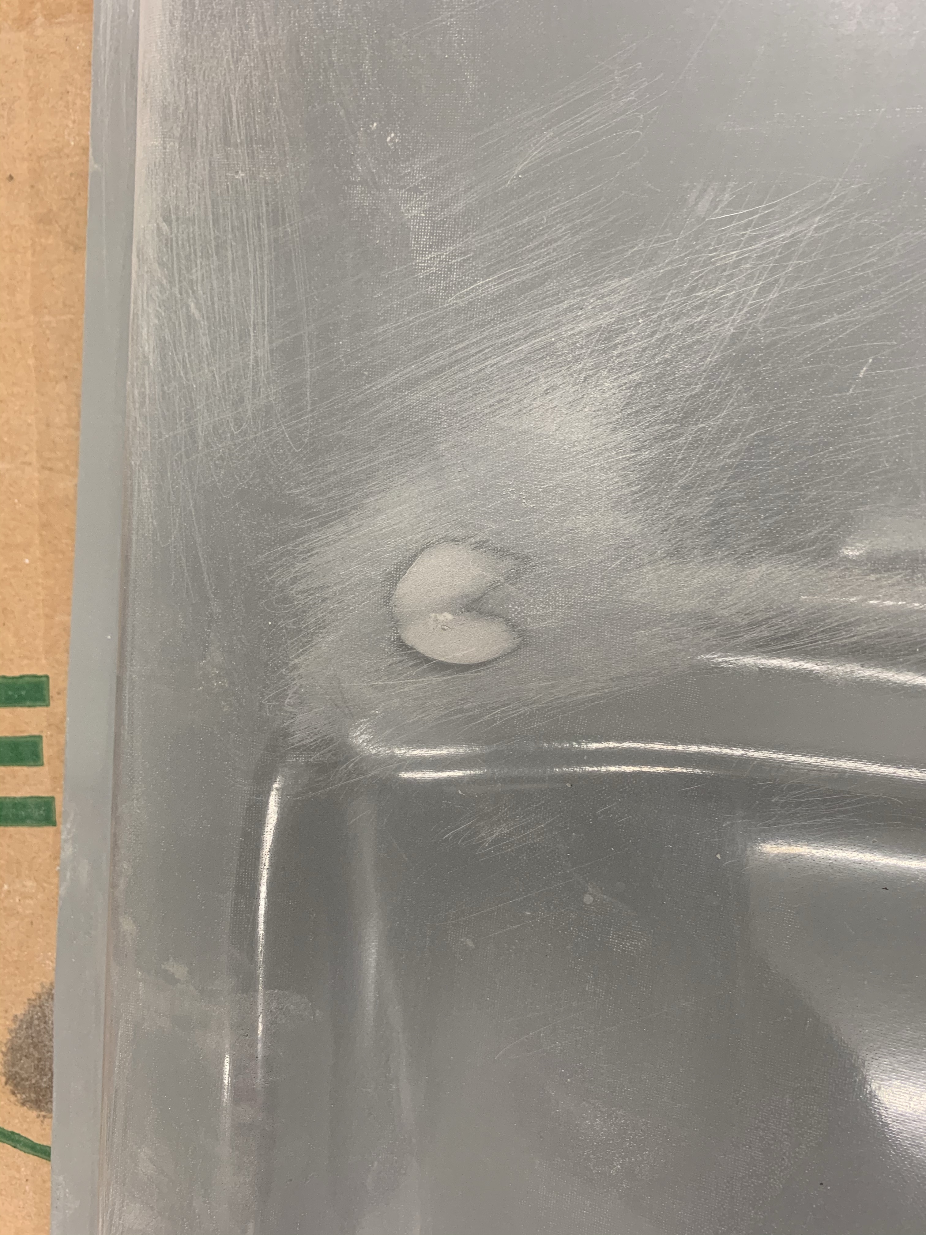
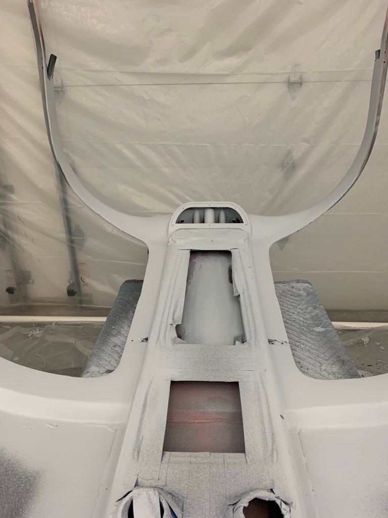
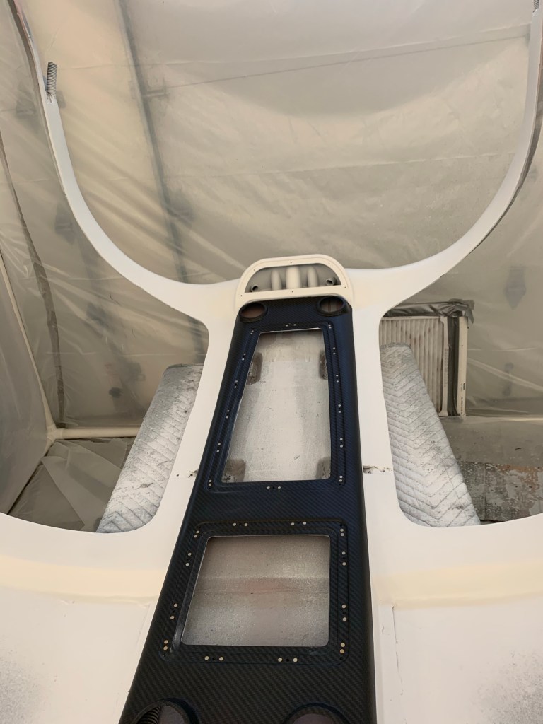
Now that the center support bar is in, it was time to finish the front of the cabin top to glass it in. I started by taking some scrap fiberglass pieces from the Aerosport headliner carrier material and drilling a couple of holes to hold things down with clecos. I then mixed up some epoxy and thickened it with Cabo so it wouldn’t run all over the place. This was left overnight to cure.
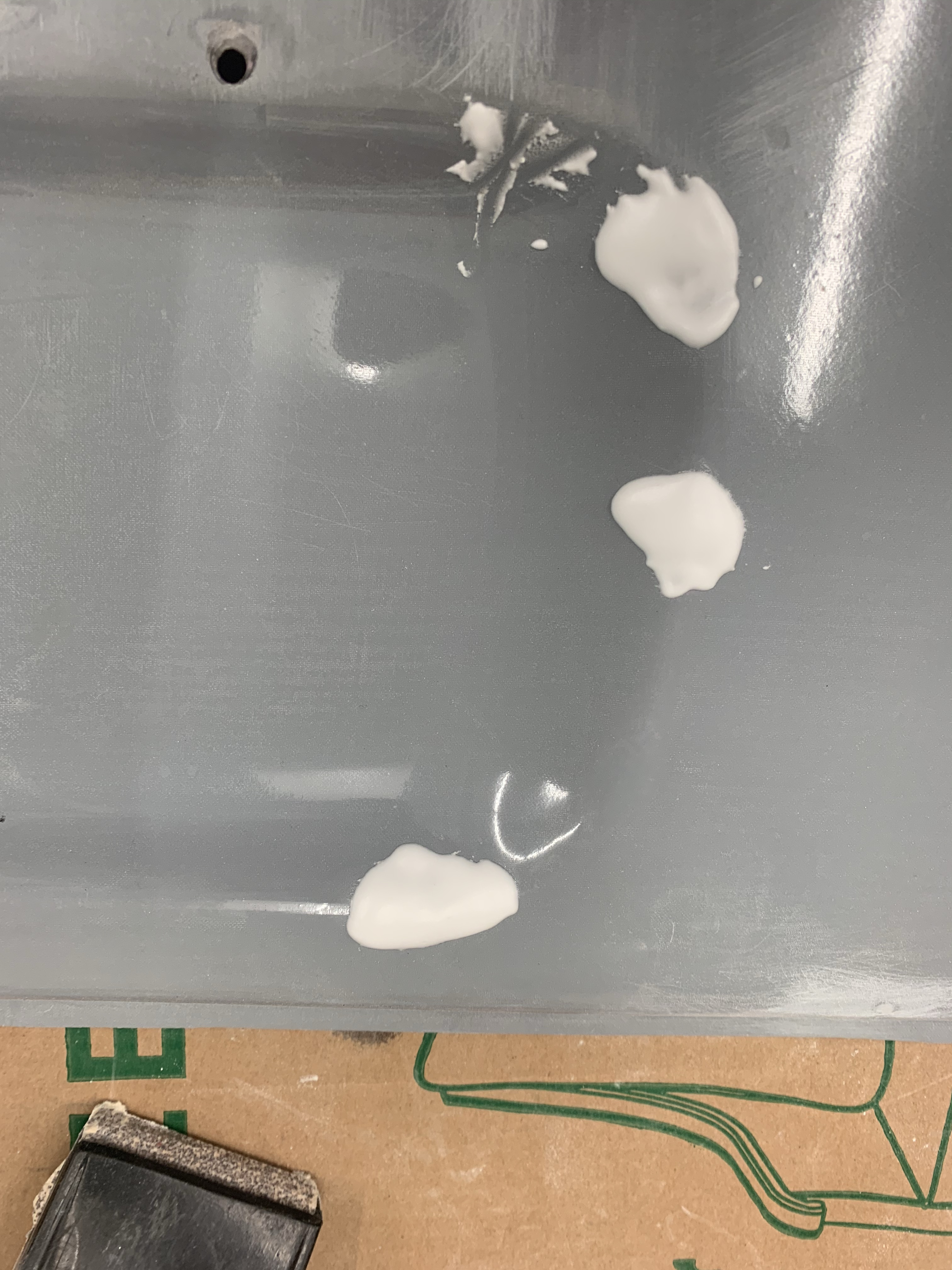
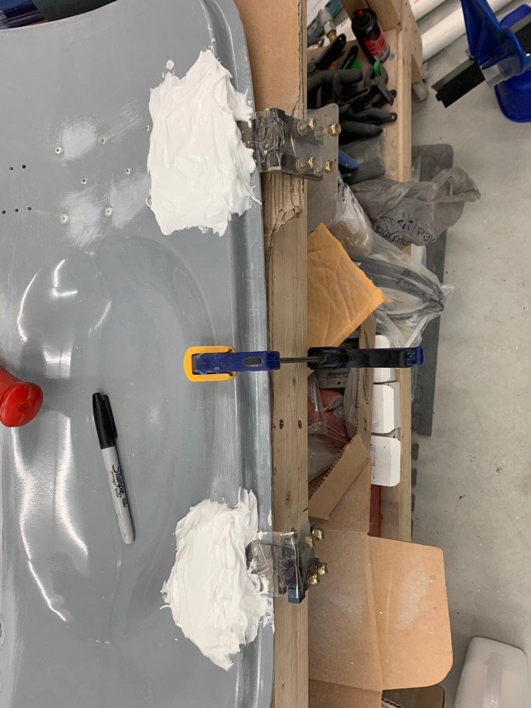
Once cured, a quick sand and then application of micro. Again wait overnight to cure.
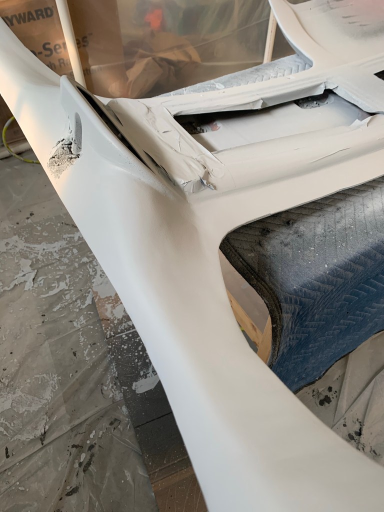
Then began the sanding process to get it to be as flat as possible and also blend into the surrounding surfaces that I had already finished.
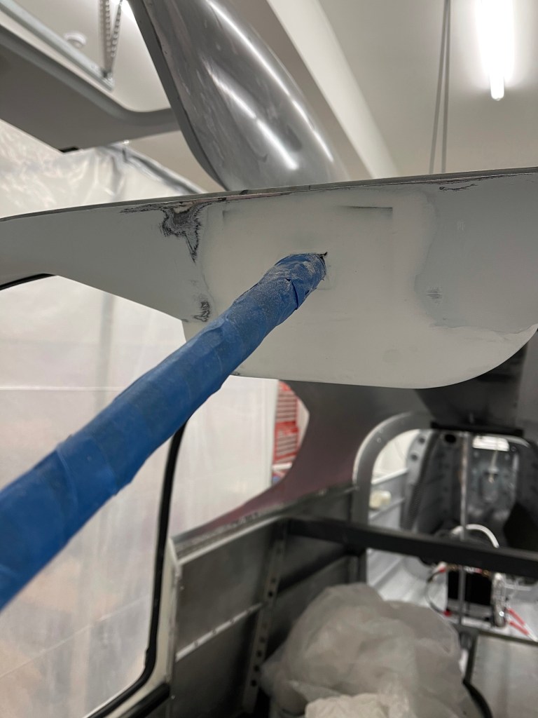
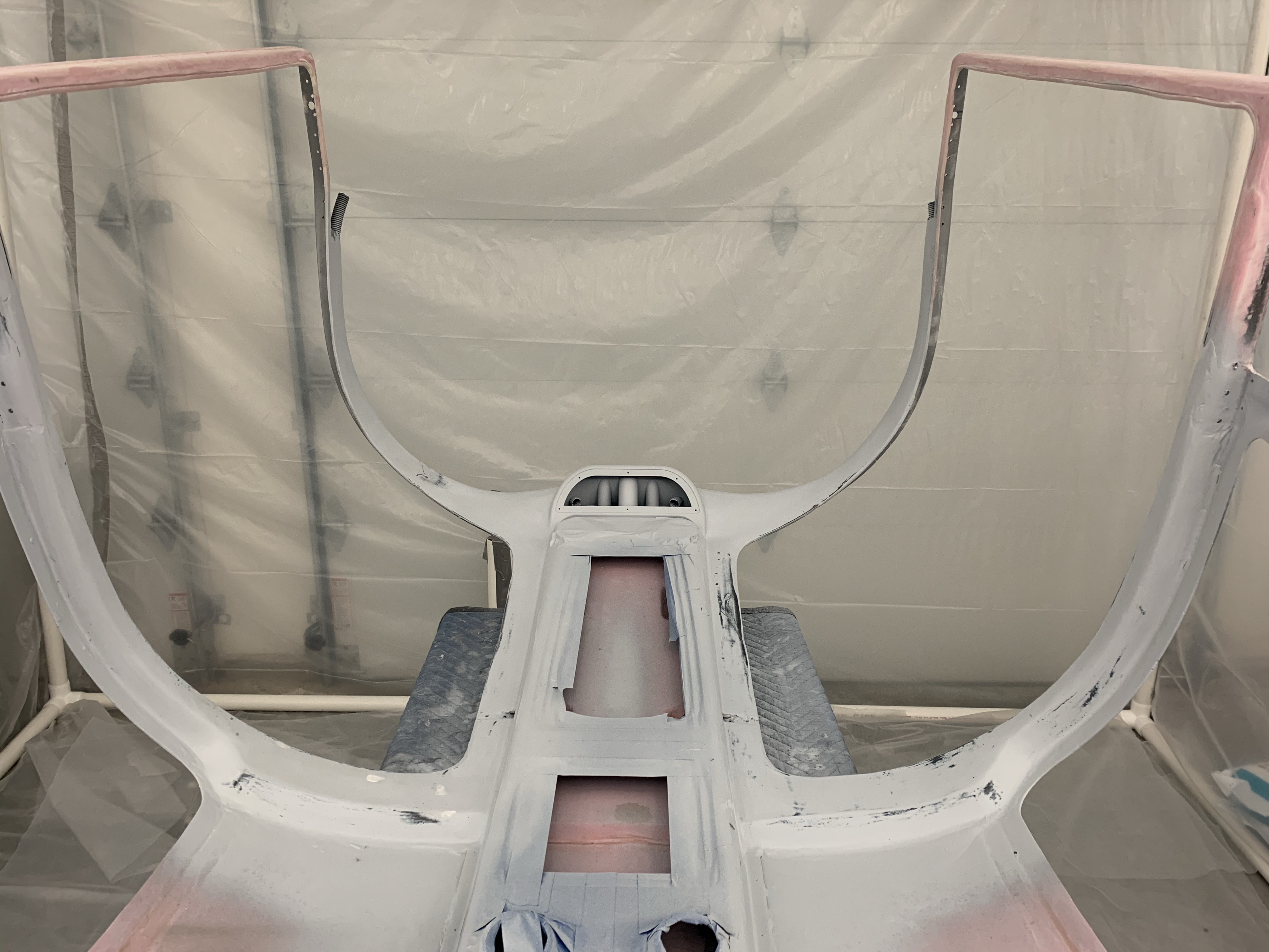
Once I was satisfied, I filled in a couple of divots with glazing compound, sanded, and applied a skim coat of epoxy with a squeegee and foam roller. That was left overnight, lightly sanded and then painting started. I followed the same process as the cabin top where I sprayed black DPLF primer, cleaned the gun, then shot K36 high-build primer. Just one coat was needed. After that dried, I sanded with 400 grit and cleaned prepping for topcoat paint.
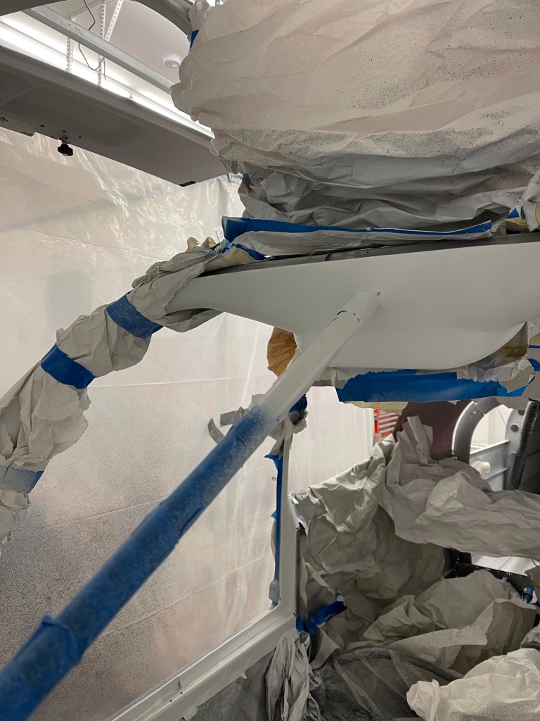
K36 primerLeft lower door frame.All the masking to catch overspray.
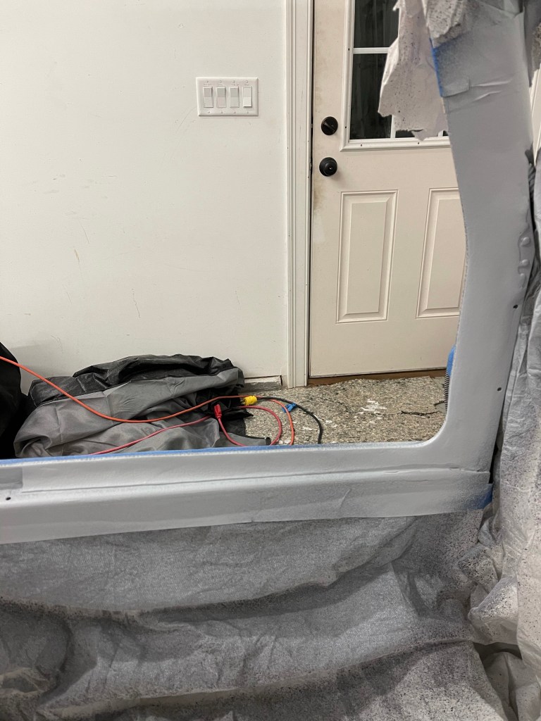
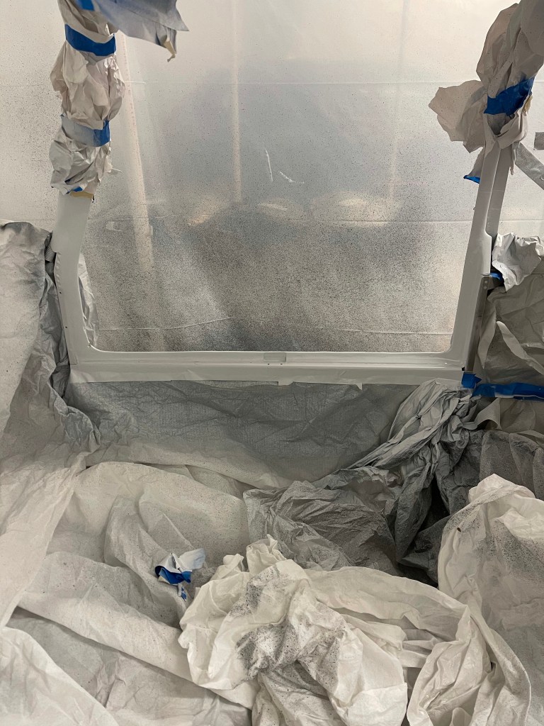
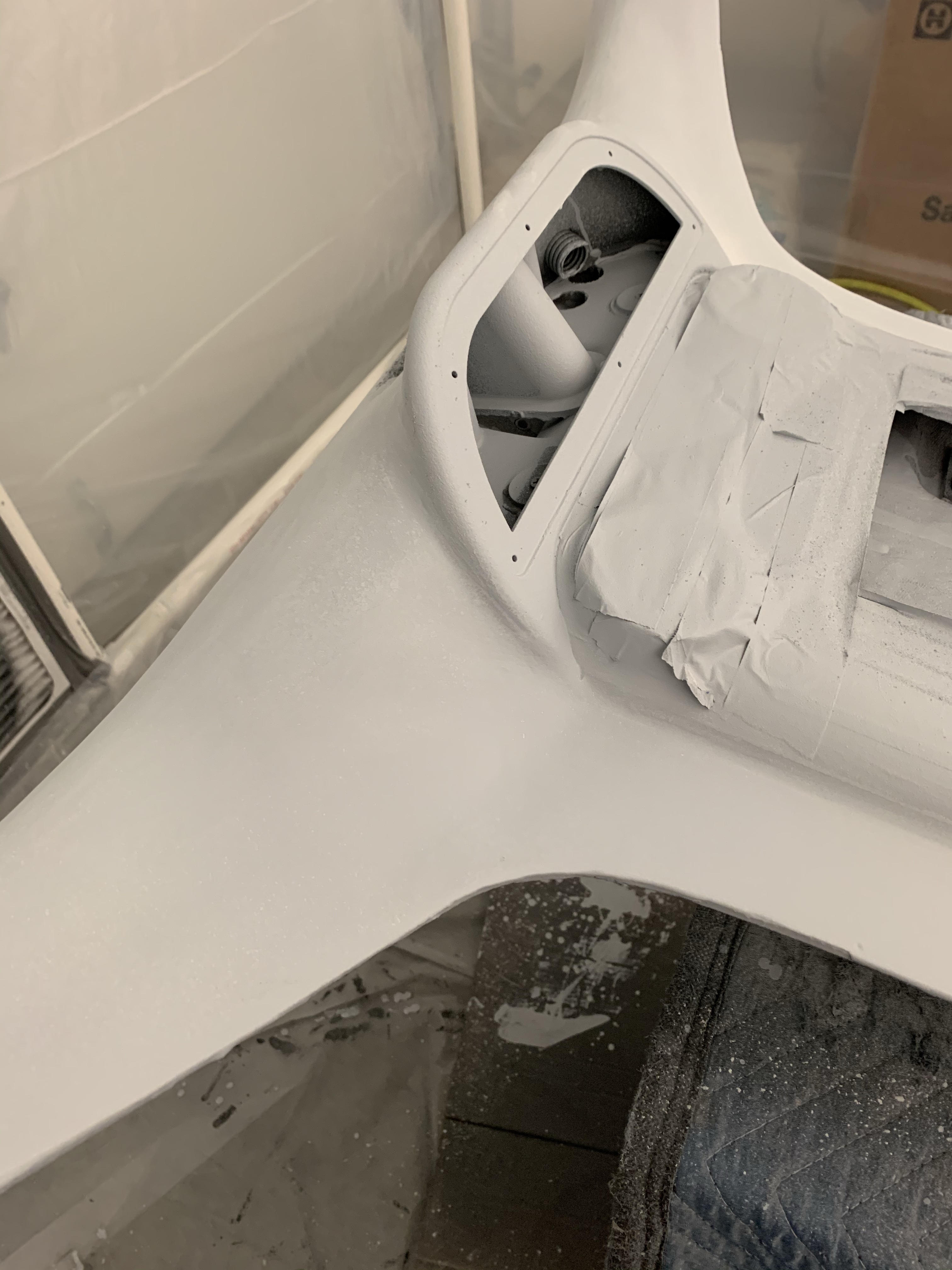
Then it was time to apply the omni sealer, top coat (Oxford White), finsishing with a matte clear coat. I donned my fresh air breathing hood and matching bunny suit due to the toxic nature of these paints. I applied the omni sealer, waited the time required to dry, followed by 4 coats of paint. Once dried, I applied the clear coat and let it cure overnight.
Masking all removed after cure
Lower door frames are not as perfect as the rest of the cabin top, but also there will be the McMaster door seal sitting here too, so not as much surface area will be exposed.
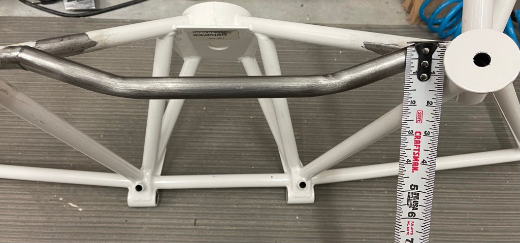
I had previously mentioned that I needed to modify my engine mount to accommodate the Barrett Cold Air Induction. I sought out a local welder and dropped it off for him to cut the existing bar out and replace with this curved one proving more clearance. I was never able to get an exact number on how much clearance was needed. I was mostly directed to leave about 1″ from the existing weld on each side and cut the new bar provided down to meet up and weld together. My welder was able to leave a little less than an inch from the weld on each side, which left approx. an inch of clearance, which should be more than enough. Now to prime/paint the exposed steel.
Initially, I had crimped some of my battery wires with a hex die hydraulic crimping tool. I was told by the supplier through ACS that that is not correct method for the terminals I had bought. I then decided to buy the crimping tool that Stein sells along with the terminals they sell as well to re-do everything I had already done. I don’t want any flakiness in the battery connections, so re-doing was simply the correct thing to do.
Test Crimp with new crimperRear battery connections complete!A view from the other side.
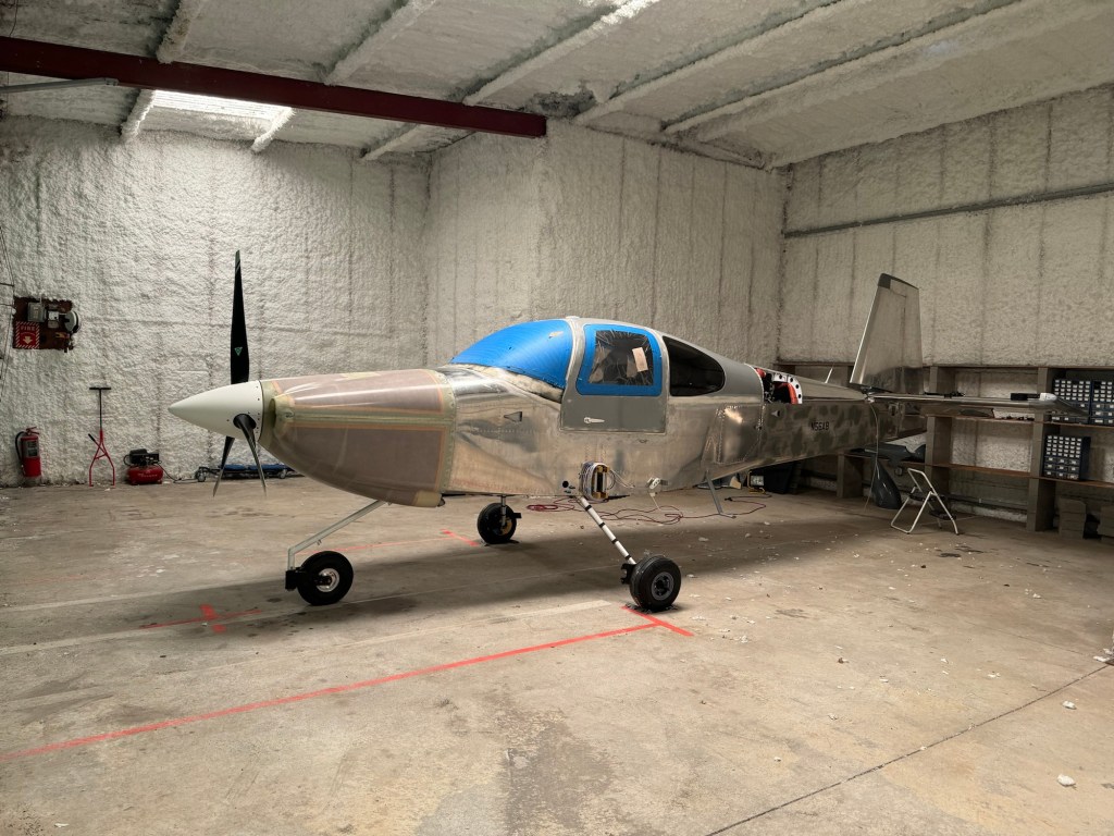
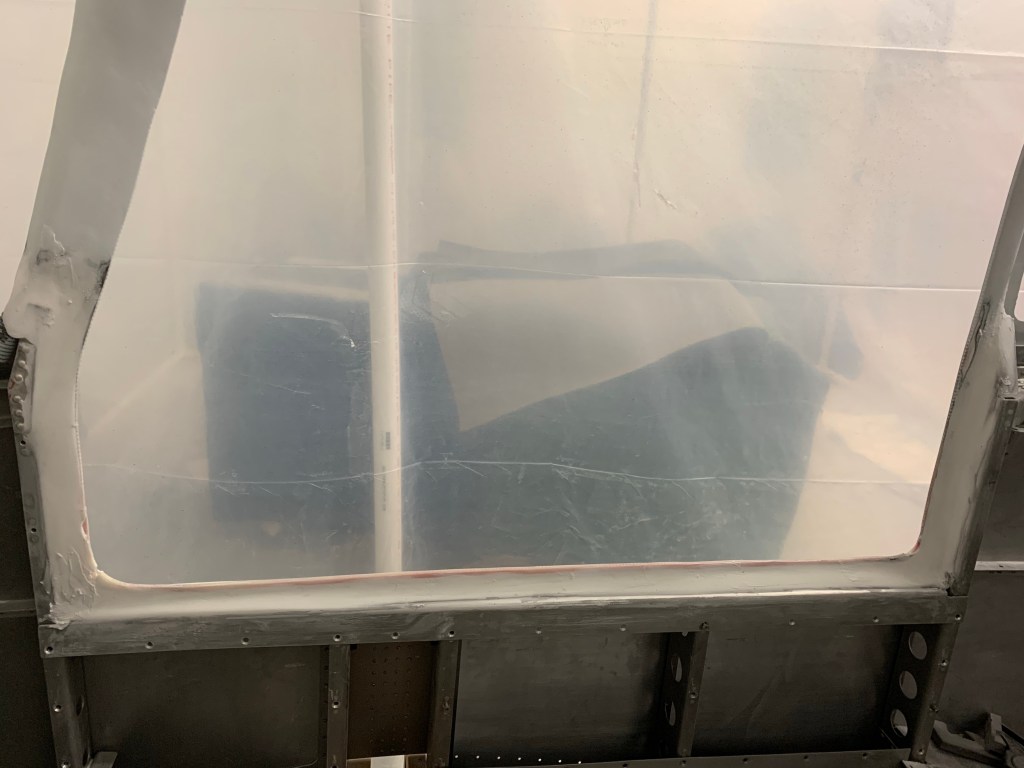
A side view of the plane as it stands. I’m just now starting to work on window installation using Silpruf. More details to come on that method.
A quick pic of the ANL bases installed on the firewall as I finished up placement of most items. There will still be a few others, but I’ve got the bulk of them done prior to installing the Firewall insulation and engine mount.
I also got my oil separator from Anti Splat Aero and the first batch of Air Conditioning parts arriving.
New Flywheel, compressor, and AC parts
That allowed me to place the 2 pass throughs for the AC hoses in the firewall prior to continuing. After a bunch of debate, I decided to route them down the right side of the aircraft. A lot of people route them down the tunnel, but it gets pretty crowded in there, especially up in the front, and you’re also competing against rudder cables and elevator push rods. So I decided to do the right side. The fittings are placed closer to the right side of the firewall.
Now that the bulk of the items were placed on the firewall, I made a template for the Lavashield insulation material. I really had planned on using fiberfrax with stainless foil over the top, but I was fighting lots of competing priorities that led me to use this instead. On this template you can see I cut out an area for the recess. I also made another template for the recess so it would be one piece.
Below is the one piece lava shield for the recess area. The larger piece will go over this making the end result look nice.
The larger piece of Lava shield mostly stuck onto the firewall with some major holes cut out. I left the backing on the upper part so that I can rivet the upper forward fuse prior to sticking it down.
I then started placing the major components back on the firewall now that the insulation is in place. Later, I cut out spots around the engine mount locations, as there should be nothing between the mount and the frame. Other things go right over the insulation.
Engine mount held in place for a quick check.
Another thing I tested out is my control servo for the oil cooler. This will allow me to control the amount of air going into the oil cooler with a knob on the panel. This will come in handy in the winter months where I can close it down a bunch and keep the oil temp right at 180 degrees.
Here’s a shot of the entirety of the plans.. followed by where I currently am in the plans. While I’m quite far along, I think I’ve reached the 90 percent done, 90% to go milestone.
Thickness of the plansWhere I currently am in the plans
After putting all the pieces back on the firewall, I decided to re-pressure test my brake and fuel lines seeing I took the connections apart. While this area isn’t a place I disassembled, I was glad I did as I found a minor leak at the post filter.
Another task prior to riveting the upper forward fuselage in place is to start routing the Air conditioning hoses from the firewall. It’s a lot easier to do it now while I have better access. Below is an overview of the hoses (2 of them) that go between the compressor in the engine compartment, through the firewall, and to the condenser on the belly of the plane as well as the evaporator in the tailcone.
Some pics of the AC hose (black hose) routing down the right side.
Connections at the Firewall. Down the right side, over the spar
One implication of going down the right side is getting the hoses all the way to the back. This required me to drill out the right baggage and rear seat pans to re-gain access.. Probably took 1.5 hours to get that all done.. Stinks to have to do this after it was all closed up, but such are decisions to add AC later in the game.
I’ve settled on running the hoses as shown below. The red line depicts the hose that goes from the compressor to the evaporator. The green line depicts the hose from the compressor to the condenser on the belly. For that one, I’ve decided to go across the rear seat front where the hose will be hidden by the flap tube cover, then go into the bay under the rear seat closest to the tunnel, and pop through the rib where the connection comes up from the condenser. I will be adding access panels to the baggage and seat pans to allow access in the future.
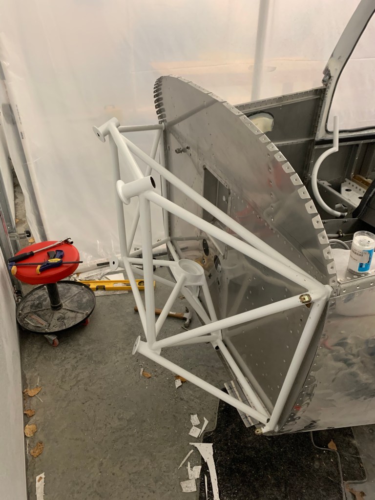
I also have received a curved bar for my engine mount to accommodate the Barrett Cold Air Induction sump. Its pictured below in place of the straight bar it will replace. This will provide some additional clearance needed for that sump. I’ve found a local welder to cut the existing bar out and replace with this curved bar. I’ll be picking that up from him in the next day or so, as it is all done and ready.
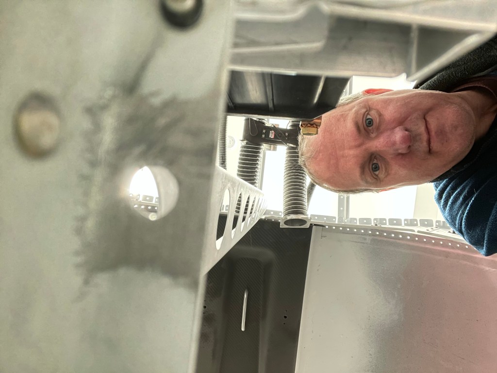
My ugly mug taking a pic of the battery area to see how good I’ve scraped the primer off of the metal where a battery ground cable will be locally connected to the structure.. 🙂
I then used the crimper to crimp the 2 AC hoses at the firewall connections and tightened them up.
Both AC hoses crimped and in place
A separate package arrived a few days later containing the shelf for the evaporator along with the scoop and condenser unit for the belly of the plane.
CondenserCondenser scoopEvaporator shelf (still to be trimmed)
Part of the choice to use the Barrett Cold Air induction sump, involves using a different cowling from Show Planes. It recently arrived and is stored away for early next year after my engine arrives.
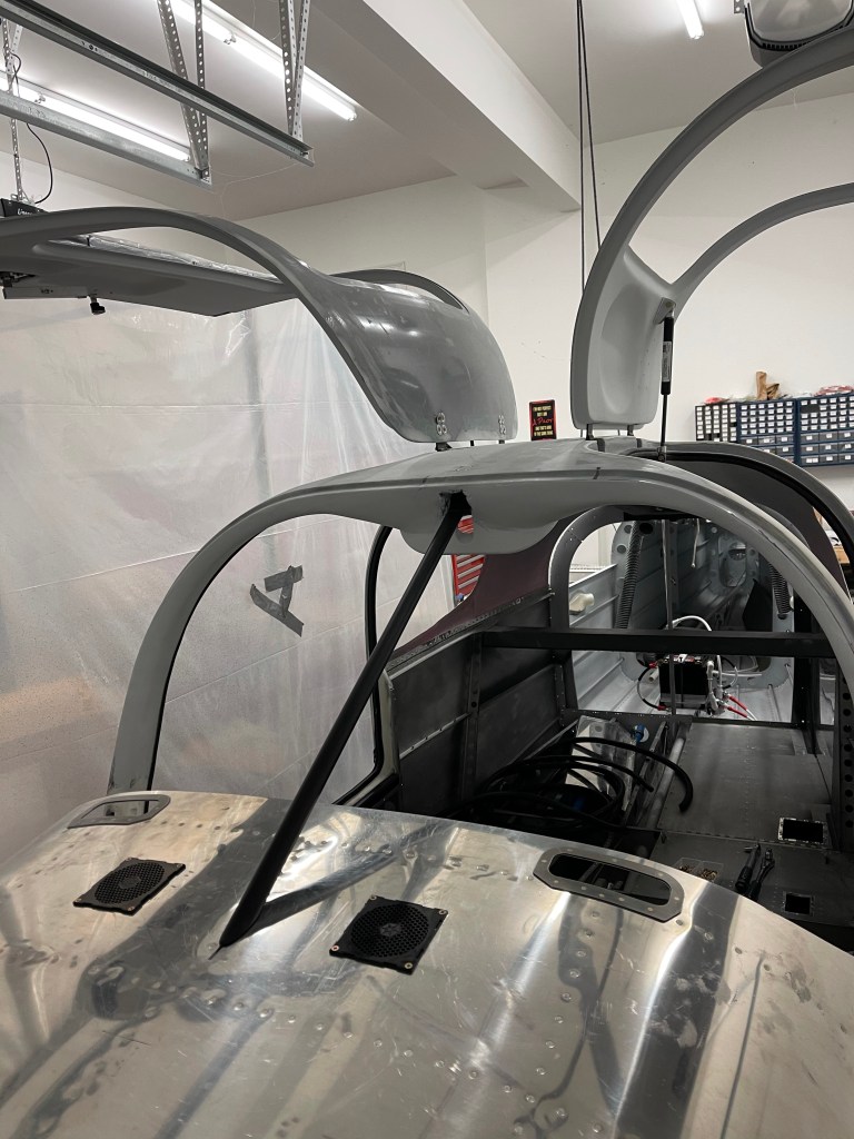
After as much up-front planning as I could do, I was ready to rivet the upper forward fuselage in place permanently. Sometimes you just have to get some of these steps done and move on to allow me to continue to make progress. This might mean that I need to be upside down a little bit more as I finish some things up front, but so be it. My wife, along with a friend both helped me rivet the upper forward fuse in place. It was definitely a 2 person job with one person using the rivet gun and the other manning the bucking bar. Below is a pic of my helper today after finishing up getting the riveting done.
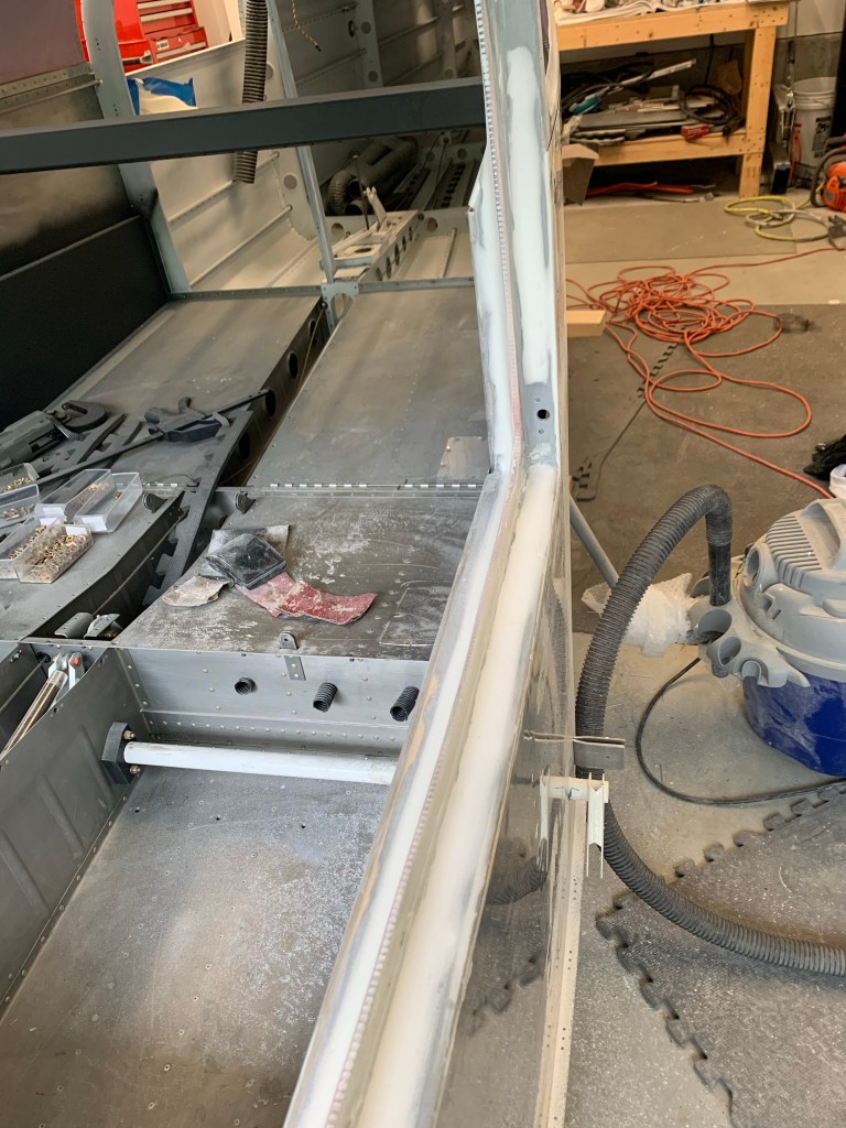
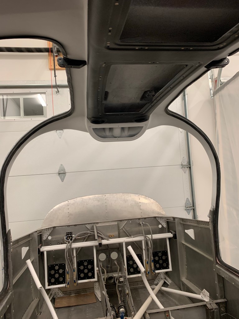
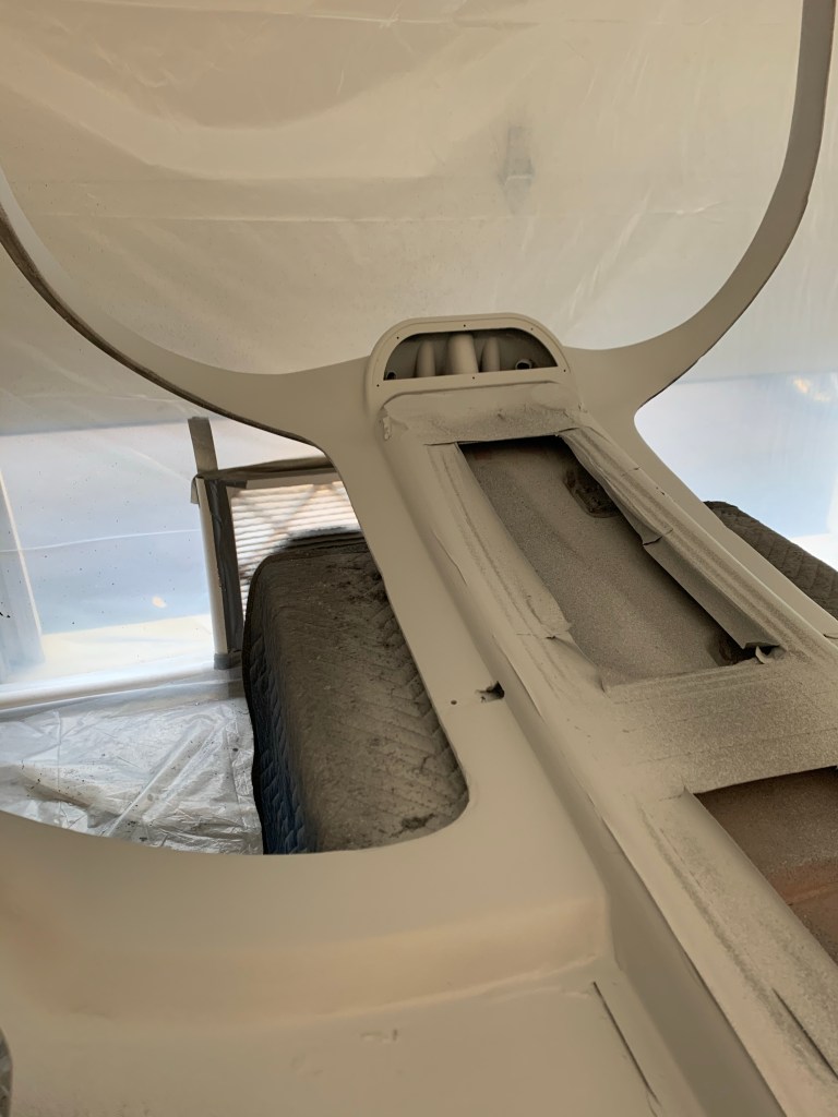
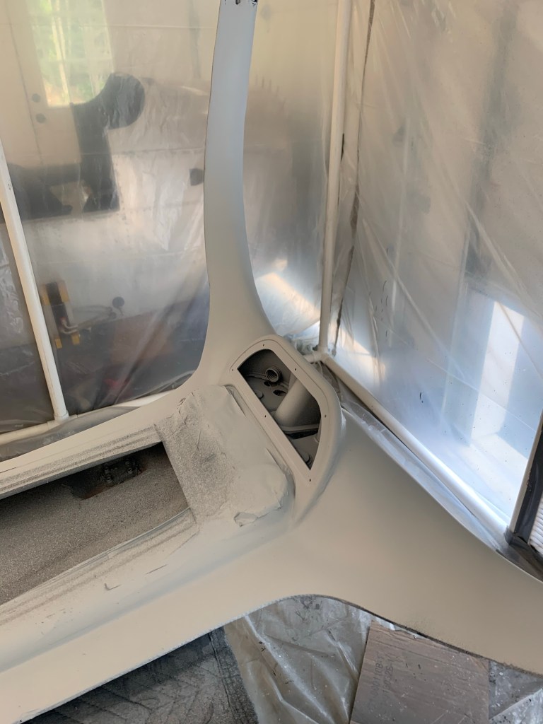
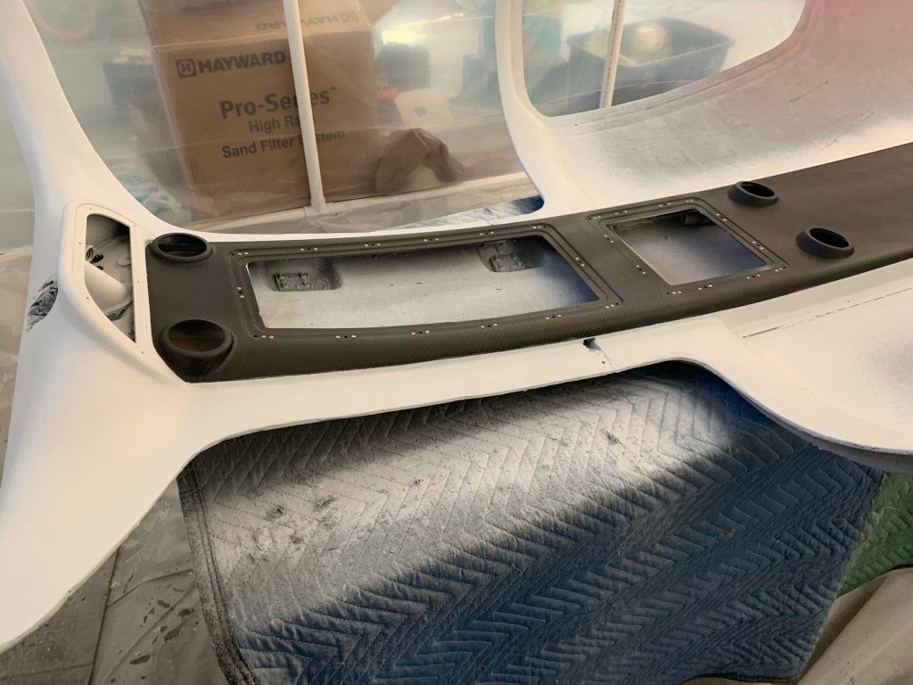
I then continued on to install the center support bar. Prior to doing so, I cut out the center support piece in the overhead switch pod. This isn’t really needed as my switch pod is bonded in and built up all around the perimeter holding it in place. This will allow better access for the nuts as well as the electrical switches etc.. that are planned for up there. It only took 10-15 minutes to get that cut done.
The culmination of the day was bolting the center support bar, which I’ve painted black, into place so I can finish up the fiberglass and interior painting prior to moving to installing the windows and putting the plane up on the gear.
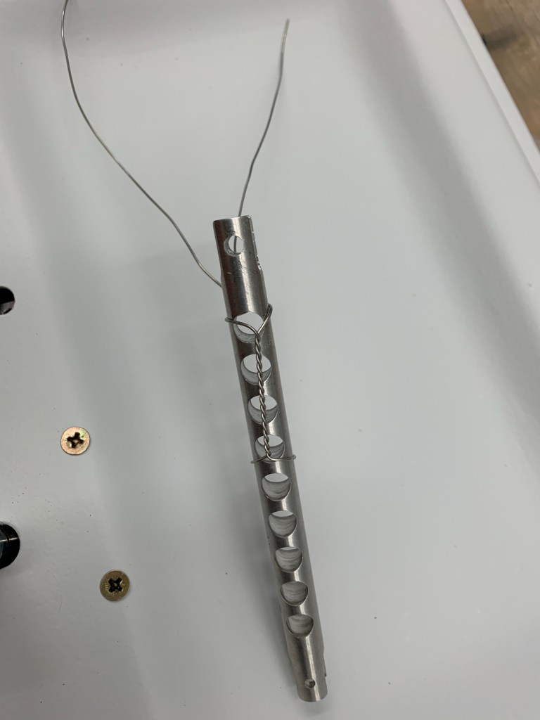
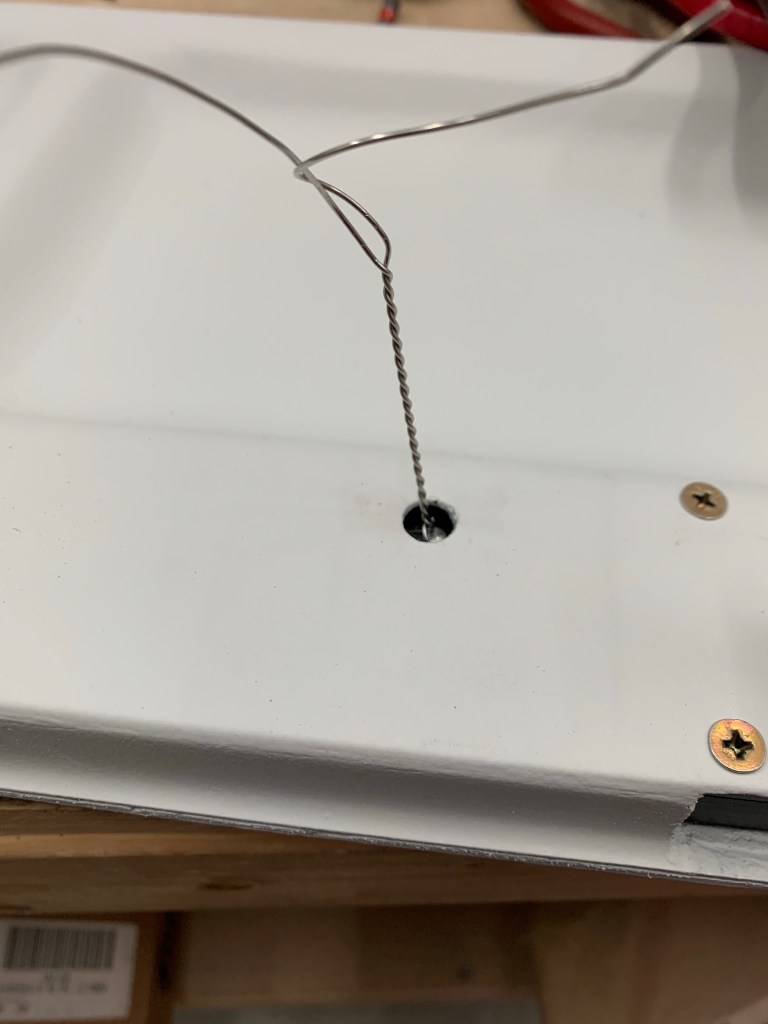
Now that the doors are painted, it was time to put them back together, including the handles and associated racks.. I pulled out the safety wire and finalized the connection between this rod from the Planearound kit to the middle rack assembly. First was to safety wire around the body of the rod leaving plenty of length to the ends to pull through the door and the access hole in the door.
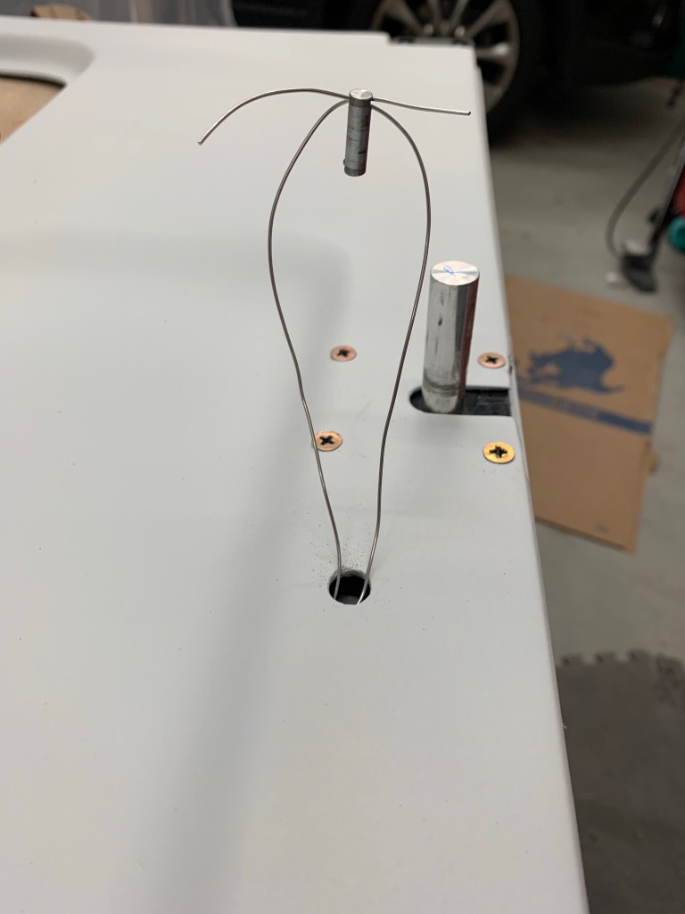
I fished the safety wire up through the hole with the help of needle nose pliers.
Then the wire is passed through the hole on the plane around pin that secures the rod to the rack (inside the door)
Pulling the ends of the wire causes the pin to slide downward and into the hole.
Pin pushed into the holes connecting the rod and rack.
Final step is to twist the wire, snip, and tuck the end into the inside of the door ensuring that it doesn’t snag up on anything while operating the hinges.
I then cut and sanded the Aerosport carbon fiber door sil covers. Reason for doing this now is I need to place the Planearound Cam blocks on the sil, and this will add a small amount of height. I also wanted to drill through this while match drilling the block to the door sil. As you may see below, I had to also cut out a notch from the micro that I had previously applied to get the cam block to sit completely on the sil and provide enough edge distance.
Door Sil CapA view of sil cap from across the plane
With that done, it allowed me to place the cam block on the sil, drill, and setup the cam location.
Cam and Cam Block on the left door.
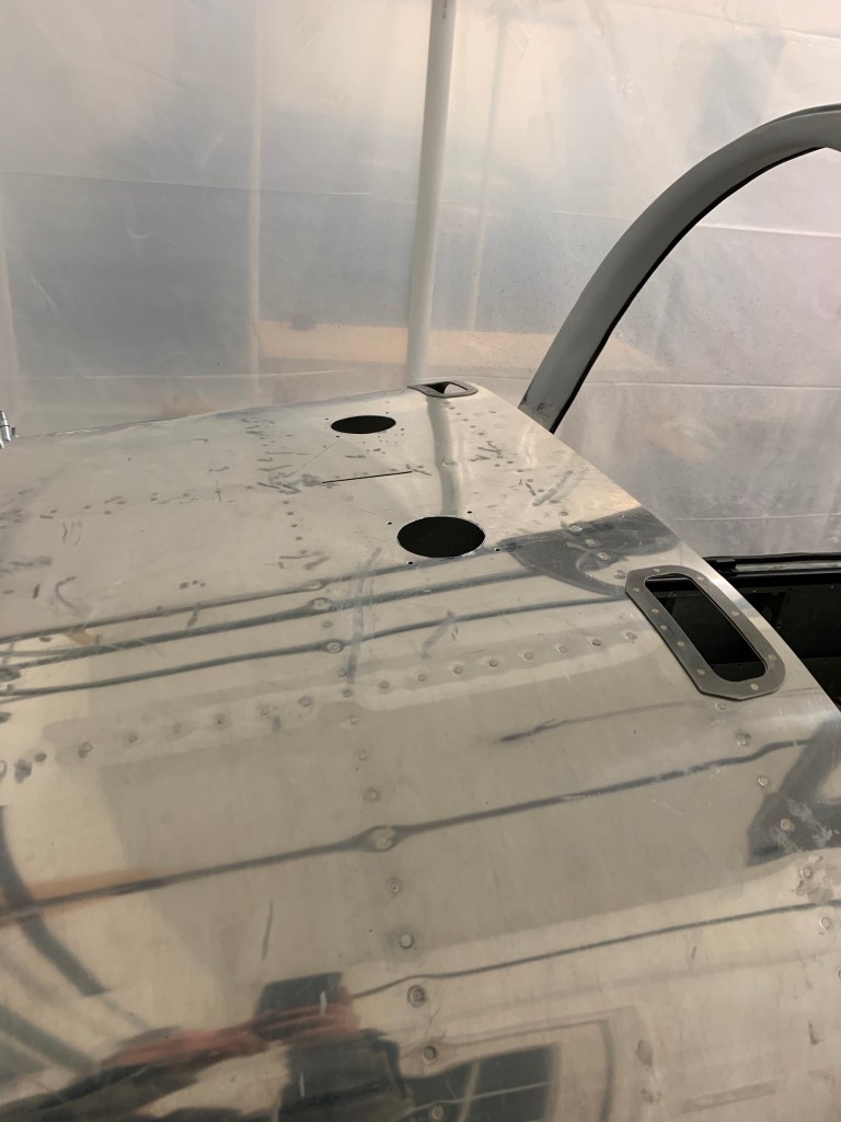
I also spent some time cutting 3″ holes in the upper forward fuselage for defrost fans/avionics cooling.
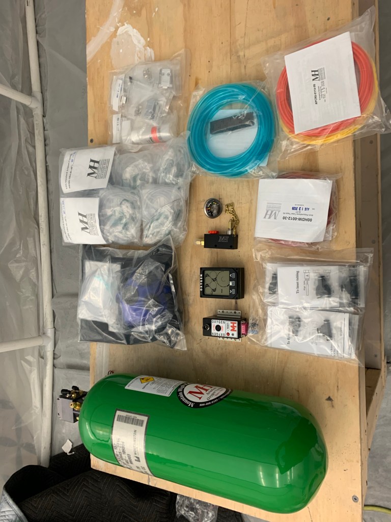
Not that I didn’t know it was coming, but I’m quickly realizing that I’m moving into the expensive part of the build. Some recent goodies that showed up are the Mountain high 4ip oxygen system and my Aerosport 310 Instrument panel!
O2!Instrument panel, side panels, and center console test fit.
I also placed a deposit on my engine build planned for April of 2021. Still hoping to go to Aerosport Power in Kamloops, BC Canada in April to build my engine with a tech for 3 days with their build school, but we shall see. Border is still closed with no opening in sight. I also ordered an Airflow systems Air Conditioning system to install as well. It will add some time and expense, but it’ll be worth it hauling the family around in the summer months and taking the edge off.
I then got to installing the engine mount by match drilling the holes and placing bolts in place as I went. One word of advise I saw from others was to start at the lower center holes and work upwards. This goes against the plans stating start at the top hole. The mount needed to be pulled outward a bit to match the center of the pre-drilled smaller holes in the firewall. All of the bottom holes aligned well from the start and allowed less stretching of the mount outward to get the hole drilled.
Engine mount temporarilymounted
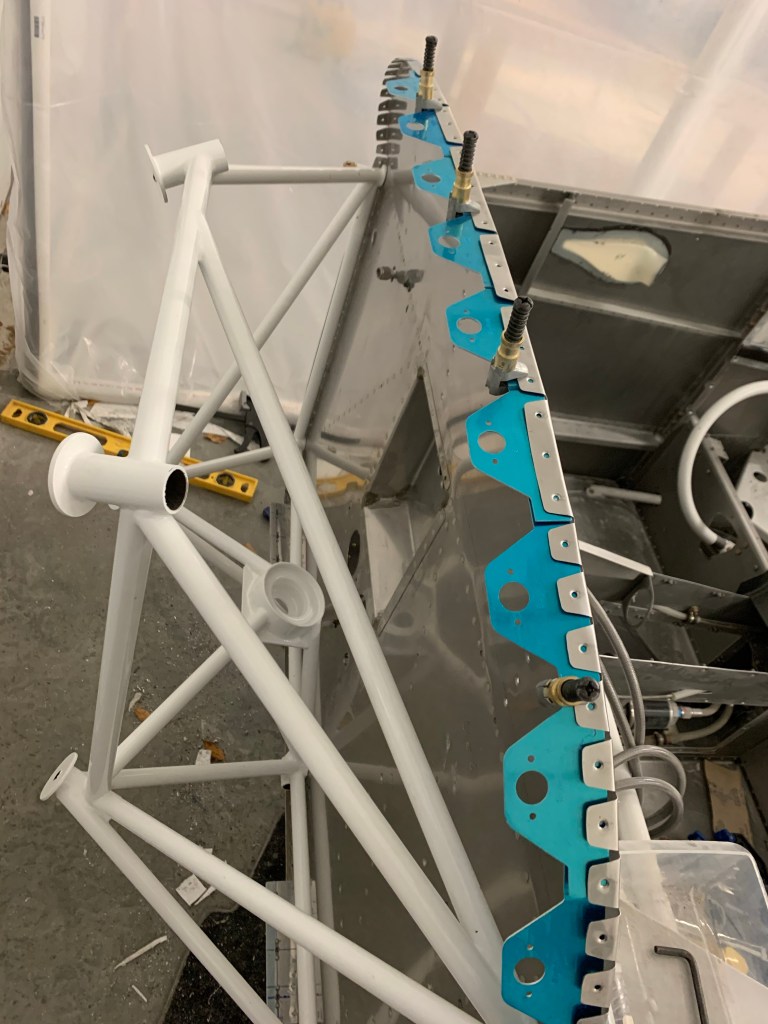
With the engine mount in place, I set out to start working on the sky bolt 1/4 turn fastener install. Really just the flanges for now. The rest will come when I am fitting the cowl after the engine is hung. I chose to install the Skybolts around the entire perimeter of the Firewall. I’ll keep the hinge and pin for the top/bottom cowl split. I played around with placement of the flanges keeping in mind to avoid any interference with the engine mount and the sky bolt receptacle.
Avoiding interference with the engine mount sets the starting position at the top of the firewall
Starting off from where I left off.. I slobbered a fair amount of micro around the bottom of the door openings to blend it with the adjoining structure and the previously done sections of the cabin top.
After sanding smooth. Another application of micro.. rinse and repeat a couple time, mostly just filling in little divots and/or imperfections.
I also used micro to cover over the screws attaching the cabin top to the structure.
Of course in between sessions of sanding and applying micro.. I got to painting my overhead panels that house the lights. I think it came out really good and hope it blends in well with the dark natural look of the overhead console.
Some other goodies arrived as well. Tires and tube along with my Matco wheels and brakes. I went with Desser Retreads and their 90 degree stem tubes. The items I purchased are listed below:
Here are the wheel, brake, axle, and spacer combos from Matco that I purchased..
WHLNW511.25 – NOSEWHEEL, 5″ 1.25
1
MSCTRA1.5 – WASHER; A6 1.50
2
WHLARV10SL – SPACER SLEEVE, AXLE RV-10
2
WHLA24SPKIT – SPACER, AXLE24 KIT
1
WHLWI600XLT-2 – WHL &BRK WI600 RV-10 CONFIG
2
WHLAXLE24 – AXLE ASSEMBLY, A24 1.25 INCH
1
I’m still a little ways away from putting the plane up on the gear, but it won’t be too terribly long from now.
Then it was back for one last skim coat of micro around the doors and I placed a strip of fiberglass over the gap between the aluminum skin and the cabin top. Lots of bouncing around working mostly off plans for now.
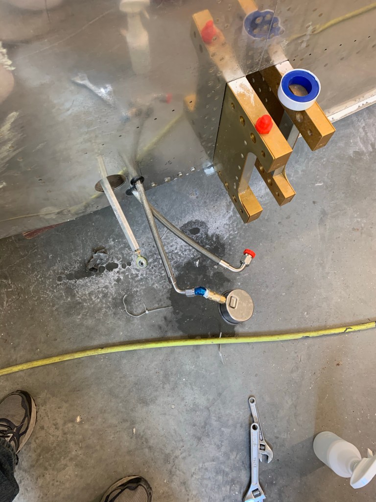
There was also one other thing that I’ve been meaning to do prior to getting too much further along and installing the upper forward fuselage sections and buttoning up the tunnel… I wanted to pressure test my brake and fuel lines to make sure there were no leaks. It would be much easier to fix now while things are still generally accessible. I used my air compressor with an inline regulator and a shut off valve to decouple the air compressor from the lines. I placed a pressure gauge on the other end. The procedure was to get pressure in the lines (I used 20-25psi for the gas lines and 50psi for the brake lines). Make note of pressure reading on the output. Shut off the ball valve and let it sit for about 5 minutes. There should be no loss of pressure. If there is.. you’d spray with soapy water to find any leaks, which I did anyways just to give me peace of mind.
Inlet to the return line on firewallPressure gauge on other endStill holding 22psi after 5-10 minutes
I then tested the fuel supply line. I had to reverse things and measure at the firewall and insert the pressure from the wings. The fuel filters and pump are uni-directional and doing it the other way.. I couldn’t get any pressure to the other end of the line.
I used a slightly different setup for the brake lines. I got a 1/8″ to 1/4″ NPT adapter to connect into the brake fluid reservoir. I used a 1/4″ NPT tee to connect the gauge into and capped off the AN fittings that go to the gear.
Picture of the brake setup
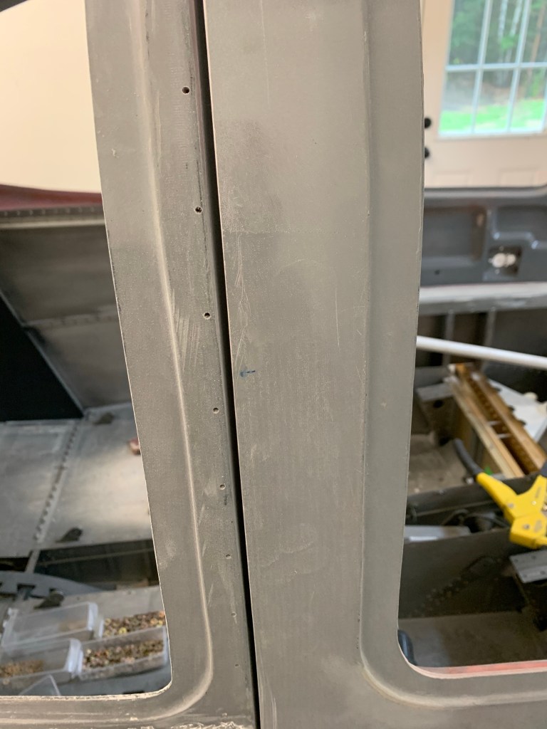
Then it was time to final gap the doors. I’m shooting for an approx 1/8″ gap. This will allow some space for paint, which will narrow that gap down significantly. To prep for that involved a lot of sanding. I re-installed the door handles and McMaster seals for this step so the door would be as close to its final position as possible. Then sand sand and more sanding. I used some thick scrap metal and wrapped 50 grit sandpaper over it to use as a gauge and to also sand back the last little bit by running it back and forth in the gap. Below are some pics during that sanding process.
Here you can see the top part is the typical gap I started with
This was repeated for the left side..
So now it’s time to get the foam tape I ordered and place it between the door and the cabin top and micro on either side of the tape to get a really nice final gap. Micro will also be used to build up a couple of low areas of the cabin top to match the height of the door.
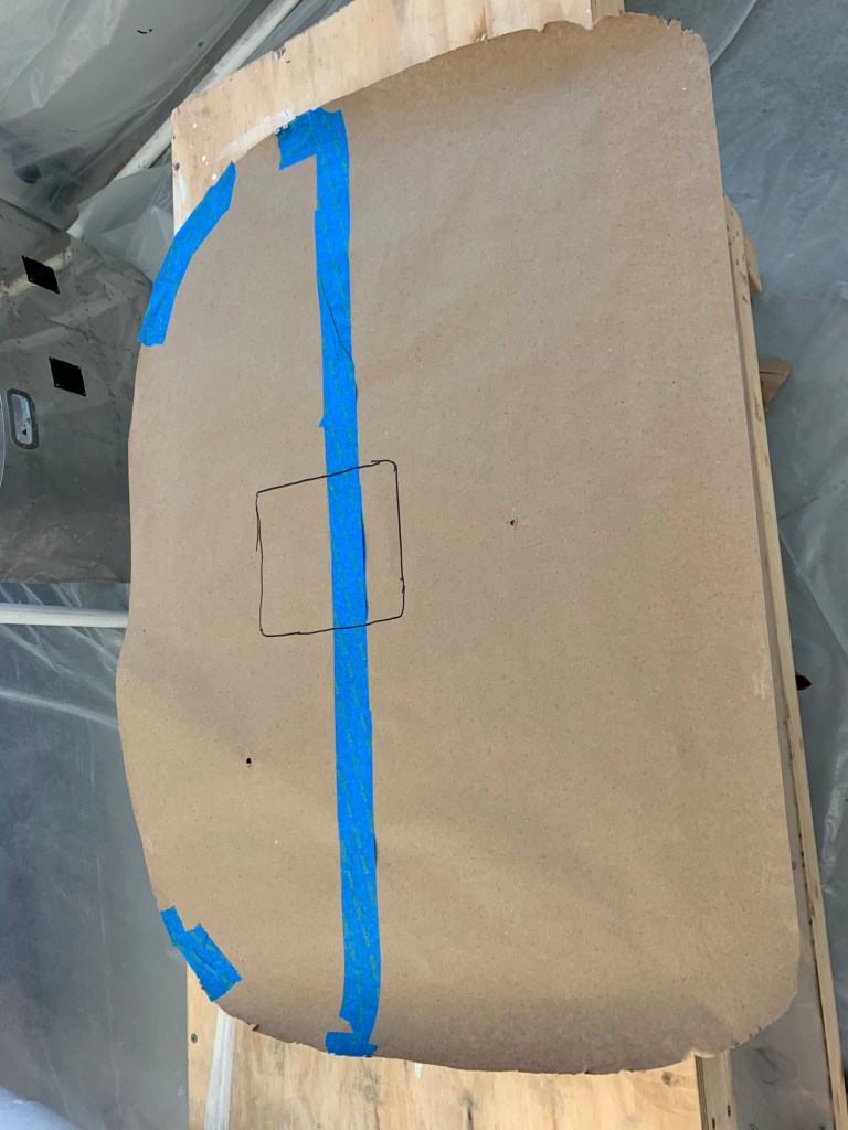
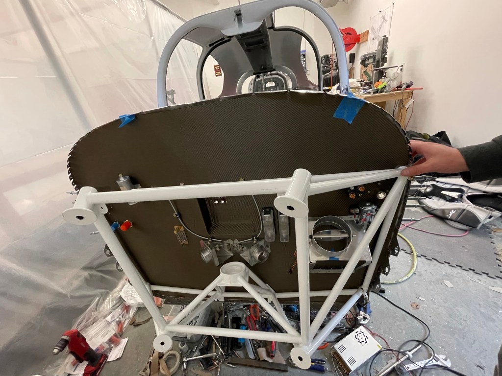
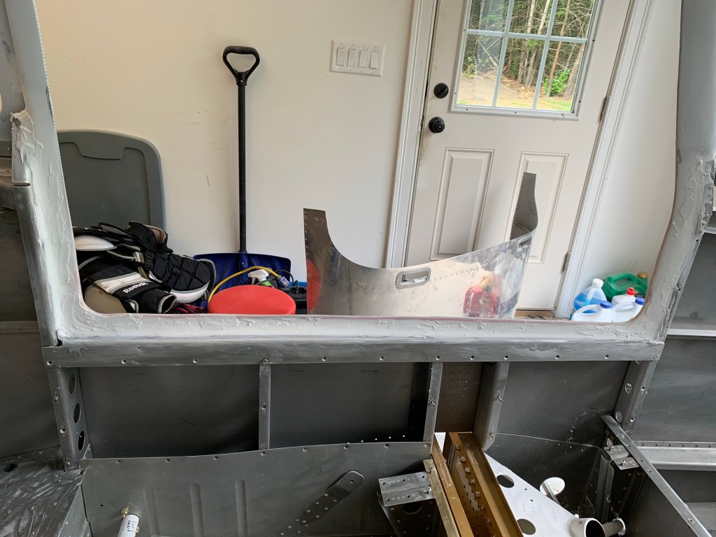
Needed to finish up a few things after the paint was done which are much easier while the top is on its back. One of those things was trimming the fiberglass substrate for the headliner. I did that by laying out paper to make a template, transferred it to the fiberglass and used aluminum sheers to cut it out.
Paper Template
Testing the fit on the right side.
The same thing was done for the left side.
Both fiberglass pieces trimmed and in place.
I then spent some time installing the Map lights for front and rear passengers, overhead lights, and the Aerosport headset and seatbelt hangers.
Front MAP lightsRear MAP lights and overhead dome lightCloseup of the front
I also got the headliner material in a Graphite color laid out to have a look at it all together.
Overhead panels complete!
I then put the door strut brackets back in and tested out the McMaster seal. The seal is actually a little short.. I guess I shouldn’t have cut it exactly previously. I suspect the build up with micro and paint is to blame. I may end up ordering another seal to make it perfect, as this is something you see every time you enter the plane.
Sitting in the back seat observing how the overhead and paint came out
Then it was on to doubling back and finishing a few tasks that I had left prior to permanently attaching the top. I had left the #12 and #19 holes un-countersunk in order to use Clecos while finishing the doors. So I countersunk them per the plans, installed the HW (loosely), and then applied a Flox/Epoxy mixture with a zip-lock bag with the corner cut out in the gaps between the lower half of the fiberglass door frame and the metal structure. I then tightened all the screws and cleaned up the edge to make a nice fillet all the way around.
Left door floxed and bolted in placeRight side screw heads sitting flush in the door sill Right door done too!
Now my plan is to work on finishing the transitions along the bottom edge of the door with micro to match the rest of the cabin top. Then I’ll be working on final gapping the doors and painting them to match the cabin top.
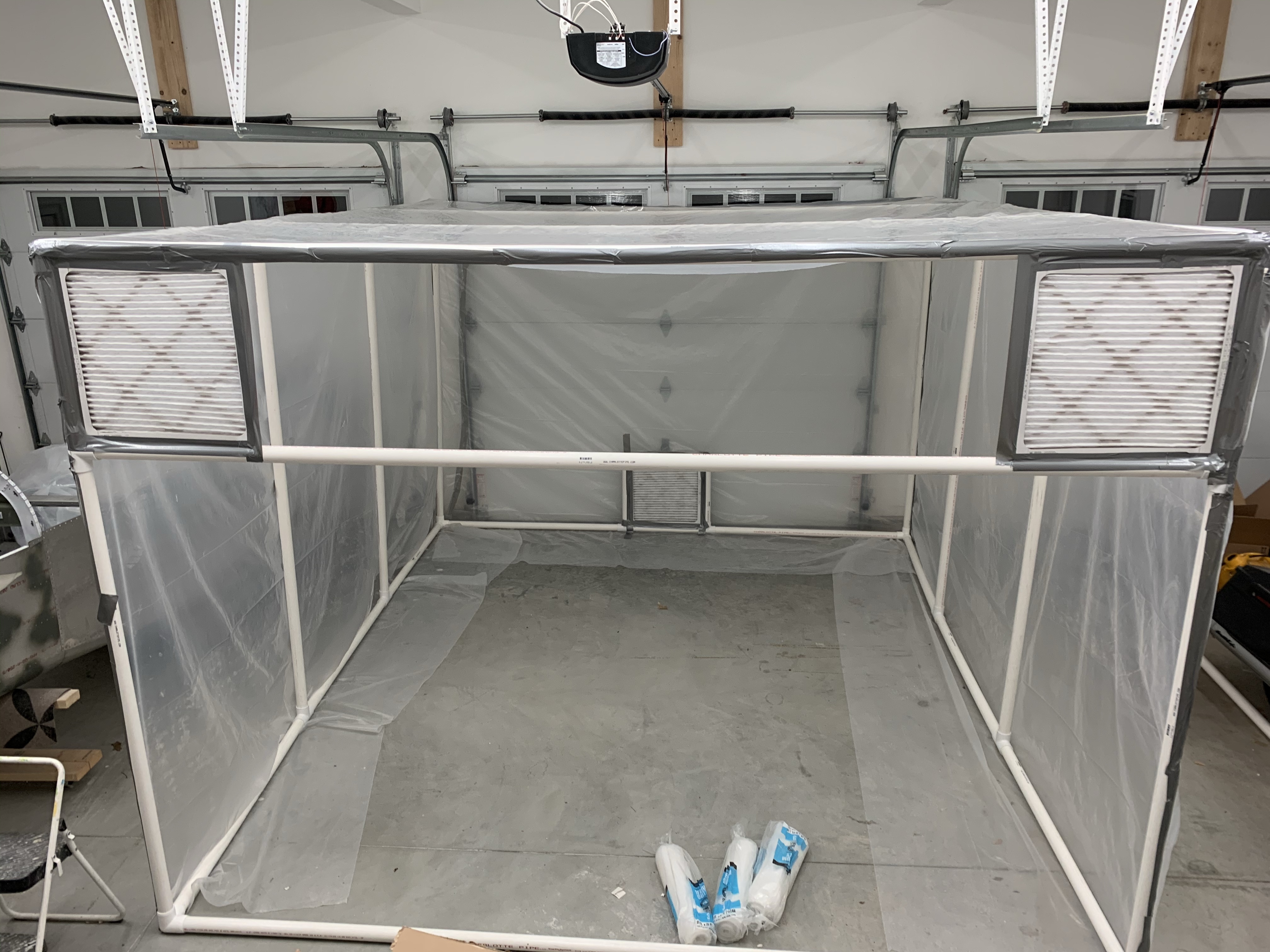
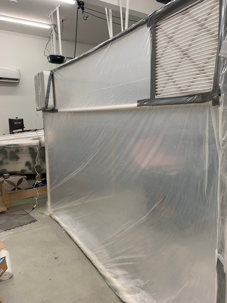
A long overdue update… Finishing the cabin top paint has dragged out longer than anticipated… After some discussion on VAF, I decided to use PPG paints. The suggested method was to use a darker epoxy based primer (like PPG DPLF) and then spray their K36 high build primer over it, wet on wet application. The darker DPLF serves as a guide coat of sorts, but also helps with adhesion. You spray 1 coat of the DPLF let it flash and then spray two coats of the K36. Let it dry, then block sand it stopping if you ever see dark come through. Clean up and do it again. The idea is to sand down the highs, while building up the lows and get something that is optically flat in the end. Knowing that these paints are pretty toxic and smelly.. I first had to setup a spray booth in my garage in order to exhaust all the fumes and overspray out. I looked online and at what a few others had done and built a 10×12 booth out of 1.5″ PVC, plastic sheeting, and a lot of duct tape. This took a while as I had to get all the supplies and do the build itself.
Rough sketch of the boothSupplies are here.
I decided to buy a 12″ “Explosion proof” fan for the exhaust. This basically is a sealed motor type of fan. I’ve seen many people say that they’ve successfully used a standard box fan from Walmart or the like, but I wanted to be as safe as possible and not risk blowing up my house. I am using 20″x20″ furnace filters; 2 for the inlets; and 1 for the exhaust. I am using standard 20″ box fans for the inlet air as those blow shop air into the filter and shouldn’t have hazardous fumes passing through them. A single 20″x20″ furnace filter would catch most of the over spray prior to being sucked out by the exhaust fan.
Booth build in progress. Filters in place
I was going for a negative pressure booth and as I got to testing it, I believe I achieved it as the plastic side walls were being sucked inward with the fans on. In this pic, I only have 1 inlet fan, but did add a 2nd one for more airflow.
Negative pressureExhaust fan at work
The next several pictures are of various stages of the DPLF and high build application. I didn’t take many pics of the black DPLF, because I had to spray the K36 high build about 5-10 minutes after applying the DPLF, so it didn’t leave a lot of time to take pics.
Not perfect, but more high build after this helped the transition.
The interior I’m going after is a two-tone graphite and Oxford white combo. Aerosport told me that their fabrics closely match SEM based paints. So I asked my local PPG dealer to make that color for me wanting to stick with PPG paints at this stage. They were really great to work with. Here is the Oxford White paint for the Cabin Top.
A couple more pics low to the surface.
While waiting for paint to dry etc.. I had some time to work on the doors. There were a few dings and nicks in the doors, which I filled with Micro and sanded smooth as shown below.
Micro over some big dings. Those dings filled in after sanding
I then spent some time on filling in the door hinge pockets. This is needed to have a continuous surface for the McMaster door seal to seat against. I bolted the hinges in place with packing tape around them and used some micro/flox/cabo mixture to fill in the pocket, while leaving enough room for the hinge to slide out.
Micro/Flox/Cabo mix over the door hinge pockets. Space for hinge to slide out. Initial sanding of the door hinge pockets.
Here you can see a coat of the K36 high build with some hints of the darker DPLF coming through after sanding.
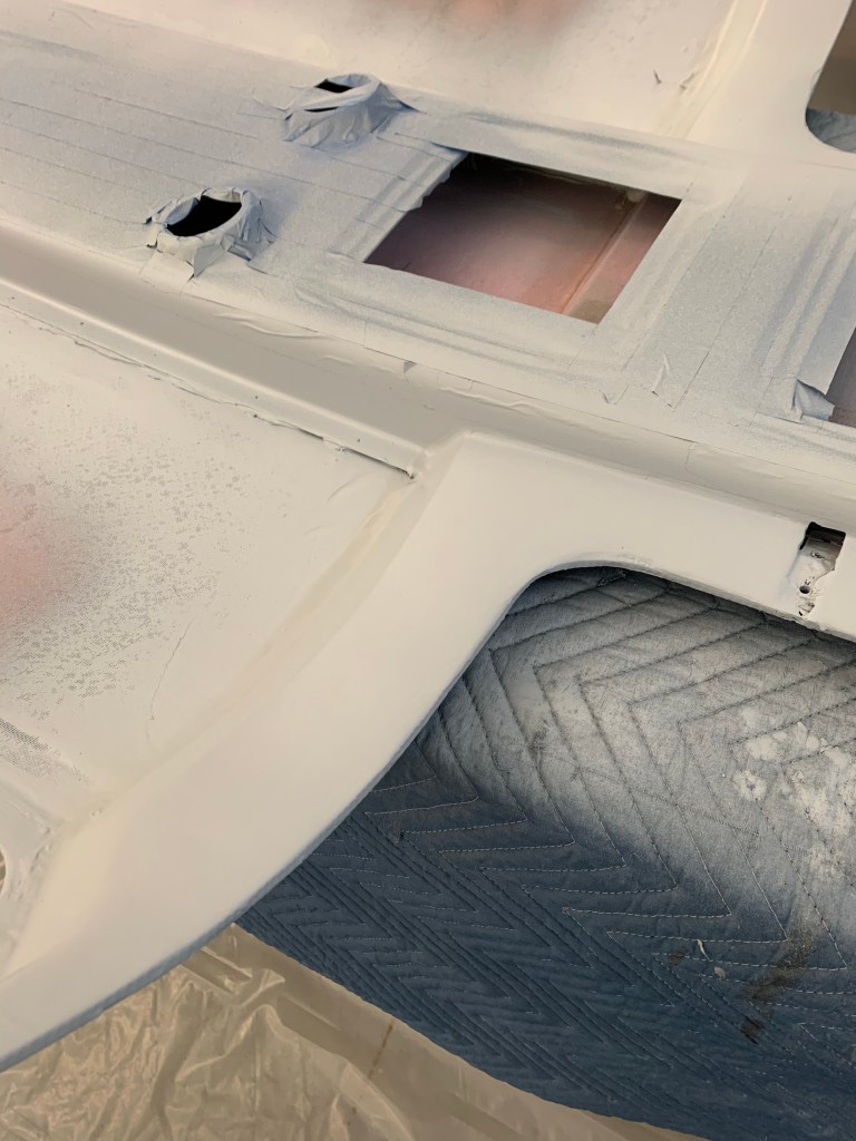
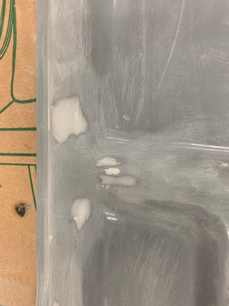
Then disaster struck. I had bought a disposable paint cup system ( a clone of the 3M system) to facilitate easier clean up and less use of harsh chemicals for cleanup.. First, while spraying the darker DPLF, I didn’t have the top of the paint cup seated well enough, and caused a slight drip, which I fixed, and then just dealt with it.. But then when I started spraying the K36, Well.. I must have not screwed down the top sufficiently enough because just after I had started to spray the K36 , the paint cup flew off of the spray gun getting paint (probably at least 16 oz.) all over everything… Leaving a big mess to clean up and me calling it a night at that point…
Huge mess of paint on the floor.. Thankful all on plastic. After wiping off the bulk of the mess..
I then had to sand and start again for that coat.. it ended up okay in the end, but very frustrating when it happened… You can see here that I got some paint splatter on my hood. I opted for a fresh air system here as I did have a 3M cartridge-based system, but with these paints containing isocyanates, which don’t have an odor, there’s no good way to know for sure that your mask is working fine. Just because you don’t smell anything doesn’t mean you’re protected.
Some paint splatter on my fresh-air hood.
Then it was on to the top-coat. My PPG dealer suggested applying an Omni sealer on top of the last K36 coat, so I did that followed by a bunch of coats of the Oxford white.
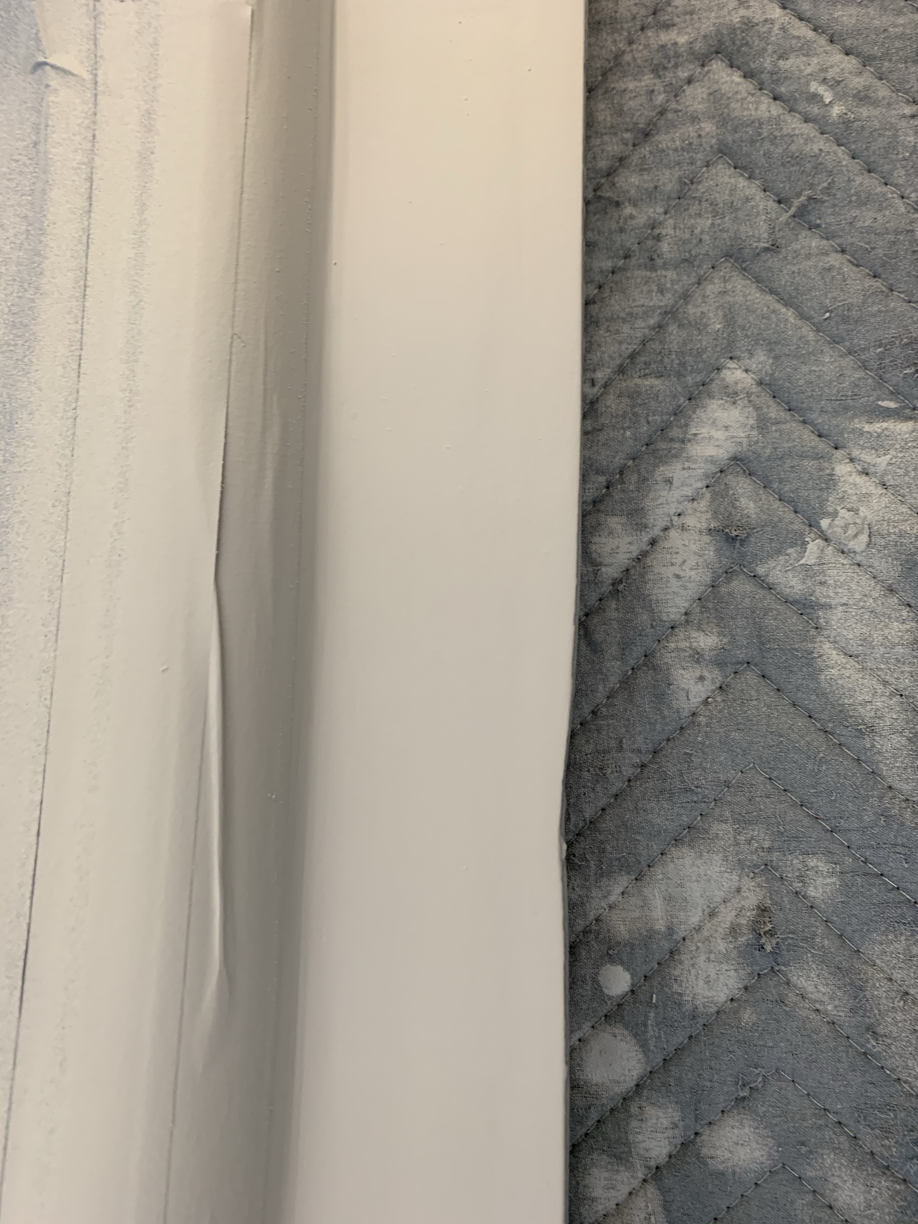
After the top-coats were done, I removed all the masking, did some basic cleanup and got ready to clear coat the darker natural looking carbon fiber of the cabin top and the Oxford white as well. The darker exposed overhead areas was sanded with 220 grit, 320 grit, and 400 Grit sandpaper and cleaned up. Then a matte clear coat by Eastwood was used to clear coat the entire finished top and below are the results, which I am very happy with. Again, not 100% perfect, but very acceptable, IMHO. The rear areas that aren’t 100% painted will be covered with a fabric headliner material. Cutting and affixing the fiberglass for that area is up next along with getting the interior of the doors ready for paint. I will likely hold off actually paining the interior of the doors until I mount the cabin top and final gap the doors.
A view from the rearLeft side. You can see the paint line is reasonably straightSimilar view from the right side.
I’ll be filling in the front area where the support bar comes in once the top is permanantly attached to the plane. For now, I need to leave this area to be able to bolt down the support bar.