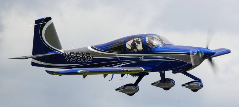
Not too many updates recently. I’m at a point where it gets harder to take meaningful pictures. So here’s a photo dump of some of the more significant updates over the last couple months
I worked on finishing up the forward tunnel by wiring the fuel pumps and getting the transponder antenna doubler installed with the help of a fellow builder. I then got the cover on and secured the throttle and prop cables and some wire bundles for the headsets in the center console.
I cut out the rear portion of the arm rest where the jacks for the rear passengers and a USB charging port.
The metal plate to cover up the hole I cut and house the jacks.
I also cut holes out in the plastic insert in the arm rest for headset jacks for front passengers.
Jacks installed.
I also installed the 2 GPS pucks on the glare shield in front of the defrost fans.
Left side of the panel area.
Lots of the panel is connected to the rest of the airplane with CPC connectors. Here, I am wiring the P1 connector which houses things like the master contactor switch, starter relay, alternator regulator connections, flap motor connections, fuel senders, door sensors, pitot heat, and boost fan for the AC.
P1 wiring complete.
Secured into place with a clamp.
Wiring like the P1 wiring will continue.. Next post will likely be when I get to the point of powering up the panel for the first time.
Wow.. What a ton of work! I’ve now completed all the Firewall Forward plumbing and wiring. The only thing left to do is to put spark plug ends on the wires and maybe tidy up a couple of wires, but outside of that.. I’m done. I also took a little extra time to revisit my baffle material seeing I wasn’t completely happy with it the first time. I changed the left, right, and aft material so each was one contiguous piece of material. Previously they were broken into 3 pieces. The aft part had some puckering that I didn’t like as well, so was addressed with this update.
The next couple of pics are from the front.
The right side of the engine.
Boy does it really get busy in the space between the firewall and the engine. Especially when you have 2 coil packs for the spark plugs.
The left side of the engine.
Again busy busy.. It really took so much time not only to wire things, but to come up with reasonable routes and securing things.
Now its back to finishing the inside wiring and getting my panel powered up!
Mostly been focused on FWF wiring. There are lots of connections to be made and properly securing the wires seems to take considerable time. Fabricating brackets.. etc..
Below you can see the metal L brackets I made along with a short straight metal piece to secure the #2 starter cable to the oil sump. The straight metal piece allowed me to mount the adel clamp for the #2 wire inwards, sort of on top of the sump. The adel clamps down lower allow for the lower voltage signal wires, mainly CHT and EGT, but also throttle position sensor wires to be secured.
Left side brackets
I also secured the AC hoses FWF along with putting the ends on the compressor side of the hoses. I secured the hoses to the forward-most intake tube, a plate secured to the left side of the cold air sump.
Left side AC hoses
The hoses connected to the FW and secured (although not in sight) to another metal bracket attached to the bottom of the cold air sump. I may also secure them to the engine mount in the middle of the run shown below.
Right side AC hosesAC hoses ready to be connected to the compressor
CHT probes were screwed into their locations in each cylinder. I then got to locating the EGT probes making sure they have clearance seeing they stick straight out of the exhaust pipe. I targeted 2 1/4″ down from the flange. I was able to locate 2 of the 3 on the inside of the pipes and #2 needed to be pointed outside due to the angle of the pipe and the heat muff being on this pipe giving few other options.
Drilling a hole for the EGT probeProbe secured in placeLeft 3 pipes have EGT probes installed. Left side coming along
I’ve run spark plug wires to their destinations. The left coil pack services the top set of plugs and the right coil pack services the bottom plugs on each cylinder.
Top Right spark plug wires routed. Top Left Spark plug wires routed.
At this point the left side is just about complete. Still need to finish the spark plug wires and the Tanis wiring to each cylinder heat element. Time to work on the right side.
Left side nearing completion.
Below are some other pics of having a bung welded into the right side exhaust collector for the SDS O2 sensor installation spot. I had a local guy TIG weld this on for me.
O2 sensor bung.
I also split the forward tunnel cover into 2 pieces like most builders do with an Aerosport center armrest/console. I also mounted my bracket for the throttle and prop cables.
In unrelated news.. I received my Aveo Engineering Zip Tip wing tip light units. I ordered these at Oshkosh, so 6-8 weeks turned into 6 months wait time, but they are here and they look great!
Prior to starting to wire all the FWF stuff, I decided to get my lower console with its side panels and the center armrest with the fuel selector and throttle quadrant installed. The main reason for this, is I need to measure for my throttle and prop cable lengths and I can’t do that with out placing the quadrant.
I first mounted the lower instrument panel console and got it match drilled to the left side panel. The same was done to the right side panel. I used a strap duplicator to match drill holes into the side panels along the top of the tunnel so we can secure them to the existing hole/nutplate locations. Once that was done, I located the center armrest into position and matched drilled 6 holes (3 per side) also to the existing screw holes on the top of the tunnel.
I then cut out the armrest for the throttle quadrant based on the scribe lines. I placed the quadrant into rough position in the armrest while it was upside down and taped it down. I placed masking tape down on the tunnel cover approx. where the quadrant will sit. Then with the center armrest placed down and screwed to the tunnel cover, I marked the legs of the quadrant on the masking tape through the top opening of the armrest. I then removed everything and drilled holes and bolted the quadrant to the tunnel cover. The holes are slotted, so you have some fore/aft as well as up/down adjustment. Getting it pretty close was sufficient. The harder adjustment was the up/down as you don’t have access to the screws with the armrest in place.
Once that was done, I had previously placed the Andair selector valve more or less in the stock location. So I drilled the hole provided by Van’s up to 3/4″ round hole for the Andair extension arm to come up through the tunnel cover. The extension was pretty close to centered on that hole, so I left it as is.. I used that hole in the tunnel cover to locate and drill the hole in the carbon armrest for the selector.
Throttle quadrant and fuel selector valve hole cut
Then the extension arm was cut to the proper length following the Andair instructions and the bottom part of the selector was placed onto the arm and test fit to the hole in the armrest.
The faceplate was put into position and I used the 4 screw holes on it to drill holes into the armrest. I prefer the orientation to be as shown below. I feel like it’s a little more clear this way as the selector will be pointing left and right for selecting the respective tank. Mounting the faceplate so that the “Lift knob” is right reading, so to speak, would have left tank selection pointing really left and right tank selection still pointing left, just not as much.
In order to be able to potentially remove the center armrest without removing the lower console nor the fuel selector valve, I used nutplates on the piece that sits under the selector valve as shown below. A couple of the holes on the armrest has to be oblonged a little bit to make the screws meet the nutplates properly, but that isn’t a big deal as the faceplate covers that area.
Nutplates on face plate screwdown plate
With all that done, below are the end result at various angles.
I was then able to measure for my cable lengths. I used some vinyl tubing I had lying around to emulate the route for both the throttle and prop cables. I marked around the mid point of the threaded part of the bearing/tie rod terminals and made sure the controls were both full deflection in the same direction (fwd/fwd or aft/aft), I then pulled the tubing out and measured the marks. I did add a couple of inches for some slop or slight variations in the install path that I measured to.
Most of my time recently has been getting all the wiring for the Firewall forward needs out through my firewall passthroughs and in a position to hook up.
This has largely been things coming from the Garmin GEA-24 and the SDS EFII ECUs.
Pilots side wires needing connectionCo-Pilots side wires needing connection.
On the co-pilots side, the main bus feed was brought from the primary alternator through a 60A ANL to the fuse blocks on the right side of the subpanel.
The left (pilots) side is mostly the GEA-24 (on the left) which has wires for cylinder head temps, exhaust gas temps, and various fuel, oil, and manifold pressure sensors.
Along with the SDS ECU box which has connections to the manifold pressure sensors, Cylinder head temps, airflow temps, wideband O2 sensor for air fuel ratio measurements, and injector power and ground wiring.
Also Coil pack wiring. This thing needs a lot of connections.
Lots of Spaghetti on the left side still to be cleaned up.
And finally, an overview picture of the panel so far.
A bunch of additional work on the AC and O2 Systems. Both of these are nearly complete now. I mounted the remote O2 Fill port in the cross brace near the baggage door for easy access for filling.
Remote fill port with gauge.
Below you can see the remote O2 regulator mostly plumbed and the line along the side wall going to the remote fill port.
I spent a bunch of time looking at what to do for an air collector to combine air-conditioned air with fresh air coming from the rear NACA vents. I didn’t have a ton of space to work with somewhat due to shifting the evaporator forward for clearance to the top J stiffeners. I eventually settled on expanding the 2″ cut on the left side to an oval 3″ cut to match the fiberglass piece provided by Airflow AC. I kept the 2″ opening on the right to feed fresh air to the overhead.
3″ duct on left for feeding AC to the overhead. 2″ duct on the right for fresh air.
Below are the 99% complete pics of the evaporator and all the associated hoses. I did use an AN3 blot with some tubing as a standoff and an adel clamp near the rear of the shelf to hold the seat belt cable up so it wouldn’t fall downward and rub against the hoses.
Left side.
I ended up using a Y adapter to combine the fresh air from the left and right NACA vents through the Aerosport NACA vent controller to the overhead.
Right sidewith Y adapter shown to combine both left and right fresh air into a single 2″ duct.
An overhead view. of the routing. I ran a little short of 3″ tube and need to get some more to finish the right side cabin flood connection.
Finally a view from the left side showing the fresh air connections from either side to the NACA vent controller to a single 2″ duct. Here you can also see the evaporator condensation drain in place, but not riveted yet to the belly of the plane.
I decided to send my Mountain High bottle back to take the regulator off of the bottle (shown on the bottle below) so I could remote mount the regulator. That will give me the option to take the tank out and get it filled at a shop somewhere. I chose to copy Joe Keys’ installation and mount the bottle to the right side behind the baggage bulkhead. I used an ELT mount along with some angle and flat 1/8″ stock aluminum bar. The angles were mounted to the J stiffeners and I used one hole of the ELT mount for attaching the mounting brackets. It’s hard to see in the pictures, but I used 1/8″ flat aluminum bar between the bottle mounting bracket and the angle/ELT mount to Secure to extend as far as I needed to and attach to the structure.
In somewhat of a paranoid redundancy of my engine bus move, I decided to modify the fuse block to add a 2nd stud. The unit has a spot (both a hole and an indent in the plastic) for a 2nd stud.. it’s just not exposed. Below is a picture of the fuse block as it came to me.
I popped the top open and inserted a second stud and then drilled the plastic to expose the stud and be able to tighten down the nut. This will allow me to have the 2 separate feeds of the engine bus connect to different locations protecting against a nut coming loose or something breaking from removing power from the fuse block.
Fuse block modified for 2 studs.
I then moved on to more AC work. I got the skinnier return ducts from Bill and installed them. This moves the whole evaporator forward to give more clearance to the J stiffeners on the top.
Skinnier return ducts installed.
With those installed, I positioned the evaporator, and fabricated new forward brackets with an angle and some scrap metal, seeing it sat much higher than the bracket provided to me and they didn’t reach the shelf. This was a suggestion from Bill.
Fabricating new forward brackets
I spent some additional time routing the hoses to the evaporator unit with the service ports easily accessible by taking the lower baggage bulkhead off.
AC hose routing to evaporatorAC hose runs with service ports shown. Hose to the dryer unit.
Then it was on to antennas.. More in the category of finishing electrical runs out to the tailcone. One of the things I had yet to finish was mounting the NAV antenna on top of the Vertical Stabilizer. I fabricated a doubler plate and drilled holes in the skins at an angle to accept the cat whiskers.
I sanded down a long wooden dowel to a point in order to insert nutplates up into the VS to hold the antenna puck in place. I’ve also seen people use a rod threaded for the 10-32 nutplate as well, but this worked okay too.
NAV antenna in place.
ELT antenna was next. A lot of builders try to mount this inside under the fiberglass. Some DAR’s, including the one I’m using, want to see this external to the airplane.. so I decided to just bite the bullet and put it just forward of the Vertical Stabilizer. I fabricated a doubler, riveted it to the skin, and mounted the antenna in place.
ELT antenna.
I also utilized another ELT mount on the left side to mount the diode with it’s heatsink and the Battery Bus relay. Shown just below and aft of the ELT.
Then it was lots of panel wiring. I first got the remote transponder mounted on the left side with some angles added front to back.
Remote Transponder mounted.
I mounted all the needed components not already on the avionics shelves to the sub panel shown below.
Subpanel components mounted.
I then put the metal panel frame and outer panel back in place and got the wiring harness re-attached to all the switches etc..
Panel wiring stats now!
A bunch of time was spent locating the fuse blocks and getting the basic power connections hooked up. Still lots to do, but this is a snapshot of where I am today. Left side, right side, and center of the panel.
Pilots side. Engine bus fuse block is here… mounted on top of the transponder.Co-pilots side. Fuse blocks were the bulk of the work so far on this side. Center part of panel. Not much going on here.. I did wire up my defrost fans..
For the first time in several years, I returned to Oshkosh with the family. It just hasn’t worked out recently based on the Pandemic as well as Jeanine being in nursing school. Seeing the RV-10 isn’t ready yet.. we decided to fly commercially to Chicago and drive the 2.5 hours north to KOSH. It didn’t seem to make sense to take a connection flight to a closer airport seeing it was a short flight. The time waiting for a connection probably would have been pretty close to the same amount of time overall. Also seeing how many flights go into and out of Chicago, any flight delays/cancellations would be easier to deal with. We were actually delayed 2 hours due to storms and a ground stop in Chicago.. No worries other than arriving a little later in the afternoon then we expected. We rented a car through Turo and the owner of the car came and picked us up at the airport, drove us back to his house, and off we went. We’ve used Turo twice now and it’s worked really well. We rented a 26′ travel trailer from Kunes RV and had them deliver it to our site the week leading up to the show. We decided to do a water and electric site. We could have dry camped, but it’s just easier with AC and basic things with a 5 year old. Flying in commercially is tougher in terms of trying to get and use a generator. So water/electic site was it!
Home for the week of the show.
We spent part of the Sunday before the show at a park at Lake Winnebago. Swimming and there was also a large playground there. Declan had a ton of fun.
The show was a lot of fun and I think Declan enjoyed it. We visited Kidventure where we checked out some planes. Declan got to fly the RC airplane with help from the volunteers. He didn’t seem too interested in doing other activities there, but I feel like he’s still a little too young for some of them. In another year or two I suspect we might be spending a couple of days there. They have some pretty neat projects that kids can participate in.
We toured the hangars and Declan seemed to enjoy that. He walked to each sign in front of each plane and asked me what it said.
Checking out planes in the hangar.
A big hit were the pedal planes. I’m pretty sure he tried all of the planes available multiple times over. He asked to come back here pretty much each day.. I would be tempted to get one of these kits for him, but he’s already pretty big for most of them, so it wouldn’t probably last that long.. Not to mention distract me from making progress on the RV-10.
Obligatory picture at the brown arch
This years show, for me, was spending some time engrossed in aviation with my family. It also served to meet several builders I’ve interacted with over the last several years. In addition, I made it a point to stop by most of the vendors I’ve dealt with over the years and put faces to names/emails/voices over the phone. I really don’t have a need for anything at this point to finish the plane, however I did end up spending way too much money on things I will need relatively soon. Below is the list
I bought a Best Tugs A3 model for moving the airplane around the hangar.
I also bought a nifty adjustable creeper for working on the airplane now in the garage as there are several things to do on the belly of the airplane. It’ll also come in real handy in the hangar. Not only for working on the plane, but for cleaning it too.
I purchased a travel weight cover and cowl inlet plugs from Bruce’s covers.
A purchase needed to finish the plane was a Halon Fire Extinguisher from H3R. I plan to mount this on the tunnel cover just behind the armrest near the rear passengers legs so it’s accessible from any seat.
With the Cold Air Induction sump there is a hose/quick drain setup to connect the Sump back to the engine seeing there is no internal oil connection like the stock Lycoming oil sump has. Tom has the below hose and quick drain setup to facilitate quick draining of oil for oil changes and connecting back to the engine with the 90 degree fitting shown at the top. These Lycomings have an oil suction screen in the cavity where that 90 degree fitting goes in the the rear of the engine. This is something that should be serviced often.. Having to remove the 90 degree fitting is a big pain because once the pipe threads are engaged and the fitting is clocked properly to connect to the hose, it’s very unlikely that you’ll be able to clock it back to the same spot each time you service the screen (basically every oil change).
CAI oil sump hose and quick drain
Tom has proposed using this small screen that goes inside of the AN fitting and removing the suction screen all together. That alleviates the need to remove the 90 degree fitting at all. To service, it’s simply unscrew the hose from the fitting, remove the screen, clean, and reinstall tightening the flared fitting. These screens are used in racing dry sump applications. At least 1 RV-10 builder has beta tested this and it has worked out well. So Tom is now recommending these.
AN screen vs the stock Lycoming suction screen. Screen goes inside of the AN fitting. A view from the other port of the fitting. You can barely see the screen peeking out when it is fully seated.
And last, but not least.. Sort of an impulse buy.. ZipTip Premiere wingtips to replace the stock Van’s wing tips. I’ve always eyed these things, but originally opted not to go that route. A few of the reasons I decided to do this were:
They are very sturdily made with no flex. I’ve seen several builders having to reinforce the insides of the Van’s tips to get rid of some of the flex.
The lights are not recessed into a cutout in the stock tips. They are practically on the leading edge of the wing and will be better for dispersing light more to the middle of the plane for landing at night.
They remove the need for a tail light/strobe in the rudder with the module having a rear facing position and strobe light on each tip.
They are much more aesthetically pleasing compared to the stock tips. The newer ones have a winglet curve shown in the picture below on a plane at OSH.
Stock photo from the website showing all the functions.Picture of a ZipTip on a plane I took at OSH.
My panel items don’t contact the sub panel, but the connectors with wire bundles did, so I cut out a rectangle from the sub panel to make sure there was plenty room for the connectors and wiring bundles with strain relief.
Cutting a relief in sub panel
I fabricated a doubler per Van’s plans
Sub panel doubler
Laid out a hole pattern, drilled, and riveted it in place.
Hole pattern drilledDoubler riveted in place
I may end up re-connecting the bottom flanges back together once the location of the connectors are in place. I then fabricated supports of the avionics trays and shelf that houses some components to the sub panel for overall support. I used a small angle riveted to the sub panel and connected another angle to it with a couple of rivets. The aft side where it connects to the avionics trays has a screw with a Nutplates for easy removal if ever needed in the future.
I also took some time to fabricate some hinged access doors to get to the AC connections under the rear seats in the first bay. These will secure down using the 2 existing screw locations on the rib. These connections are for the AC condenser.
Access door in rear seat panA view of the access to the AC connection on bottom skin
Additional work was started on the AC evaporator unit. First up was to mount the return air ducts.
Right return ductBoth ducts on and interior holes cutCap put on
I’m adding a 3″ blower fan to boost airflow into the overhead.
I then placed the flat upper panel from Airflow into position and started rough fitting the evaporator in place on the shelf.
You can see that I will need spacers on the front mounts. I’ve seen several others have to do the same thing. Also I ran into a clearance issue with the J stiffener on the top as shown below. Bill from Airflow said he’s had others run into the same thing due to variation in the units from his suppliers. He’s sending me shorter return ducts to move the unit 2″ forward to solve the clearance issue.
Clearance issue with expansion valveManifold is very close as well, but some gap is present
Just before Oshkosh, my seats from Aerosport Products arrived. They came out great! I had to place one into the plane in rough position to see what they look like.
While waiting for AC parts to arrive and needing to finish up some things in the rear of the plane prior to putting the evaporator in place more permanently, I decided I needed to finish some remaining tasks out in the tailcone.
I installed my ELT unit and wired things up to the panel.
ELT in place
I also worked on plumbing my static line from rear to front. This thing needs to go multiple places, so I’ll likely be using a manifold style connector behind the panel vs a long daisy chain.
Static port routing out back.
Pitch and Yaw servo installation was next. I used a laser level to help drill the hole needed for the pitch trim arm to connect to.
Prep for drilling pitch trim holein bell crank
Crawling into a small and uncomfortable space is always painful. Here I am in the back sort of on my side to drill out 4 rivets so I can attach the yaw bracket to the airframe.. Wish I had waited to buck these 4 rivets, but got them drilled out.
Fun in the tailcone. Pitch and Yaw servo brackets in placePitch and Yaw servos in place
I finished up the routing of the AC hoses down the right side of the fuselage. The hose going all the way to the tailcone dives down towards the floor and goes through the bottom most lightning hole to make sure it doesn’t interfere with the flap tube in the next bay aft. I placed a small piece of angle on the angle attached to the side skin, used nut plates to screw the 2 angles together and then utilized a nut plate to keep the hose from rubbing on the angle attached to the skin.
View of the metal piece riveted in all 4 corners of the lowest lighting hole with a bushing through the center for the hose to pass through.
The hose destined for the condenser scoop, goes across the flap tube area on it’s way across the tunnel and to the 1st bay under the left-most rear seat.
Hose continuing to the tailcone under the right rear seat.
I utilized Adel clamps anchored to the step to route the hose inward and keep it away from the bolt holding the step in place. It then makes its way aft to the tailcone.
Similar for the hose going from the condenser to the tailcone.
With the hoses done short of crimping on the ends, I started working on the evaporator shelf by using cardboard as a template.
I test fit the cardboard until it was trimmed correctly to sit between the longerons.
I then used the cardboard to mark up the fiberglass shelf and trimmed it, sanding a little bit to get a good fit. Shown here as well are the 3 holes matched drilled into the shelf brackets that get riveted to the longerons.
One other small task was to trim the upper cowl ramps and add a “wall” so that the baffle material could sit in-between the upper air ramp and this “wall” so it has something to push against.
Using some scrap fiberglass to trim up a “wall”
I then mixed up some flox and bonded the “wall” in place with a small “D” shaped piece to provide support against the cowl wall. This was repeated for the other side.
One nice day, I decided to head outside and paint the interior panels. I ordered the lighter tan ones knowing that I was going to paint them a darker color. I think they came out nice!
I ran into a snag with continuing with the evaporator install so I worked on completing disassembling the panel. I removed the wiring harness and separated the metal sub frame of the panel from the carbon fiber.
Wiring Harness removedCarbon fiber panelwith avionics trays. Metal subframe with shelf for various components.
I spent some time getting the metal subframe in place, followed by the carbon fiber panel with the avionics trays. This first test fit was mostly done to mark the sub panel where I’ll need to cut away and reinforce making room for the connectors on the back of the 650 etc.. Not a whole lot needs to be removed just a small rectangle near the bottom and really just for the connectors and so the wiring harness doesn’t get bent too much.