Aerosport Interior Panels

Couple of small things to finalize about the gear installation prior to moving on to getting the interior panels trimmed.

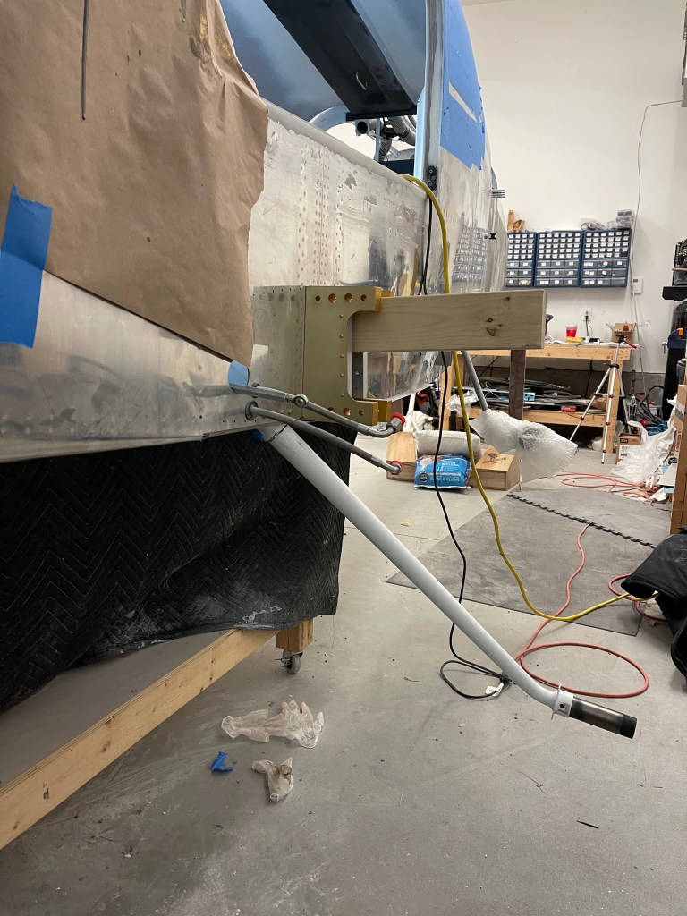
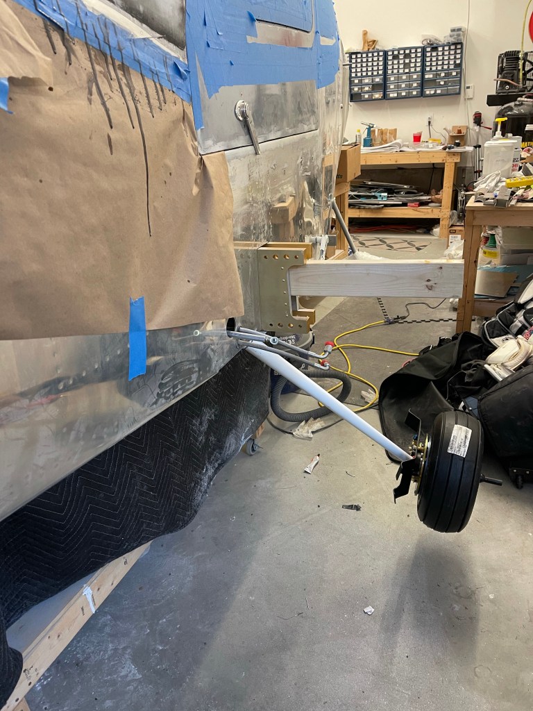
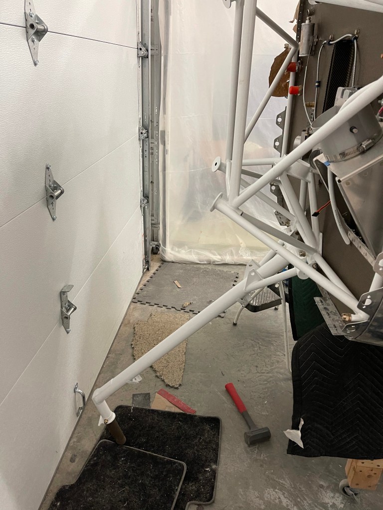
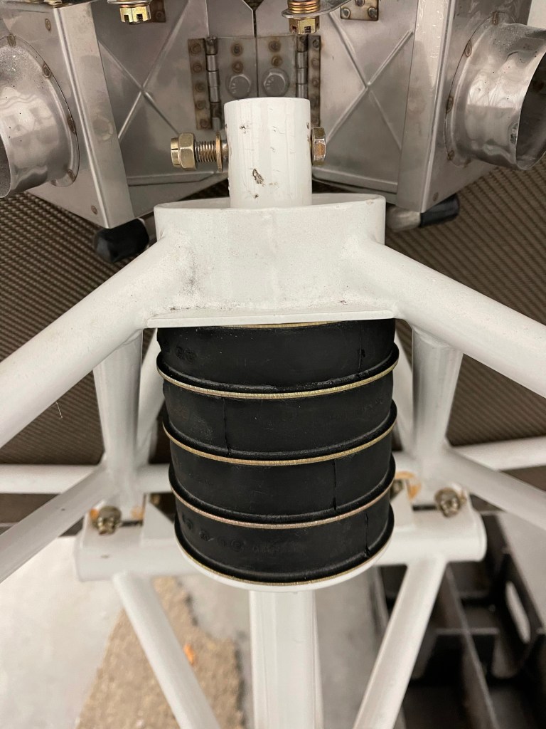
First was to tackle the hardest bolt in the airplane to install. The bolt that holds down the nose gear donuts. This thing requires a lot of compression to even get the bolt hole to line up. Luckily, I have a tractor. So I strapped the engine mount to my bucket and let the hydraulics do the work. Even still, the bolt was stubborn. I feel for others who have said they’ve had family members hanging off the engine mount while someone pushed the tail upwards while trying to muscle that bolt in place.

Tractor comes in handy!
Hardest bolt installed!

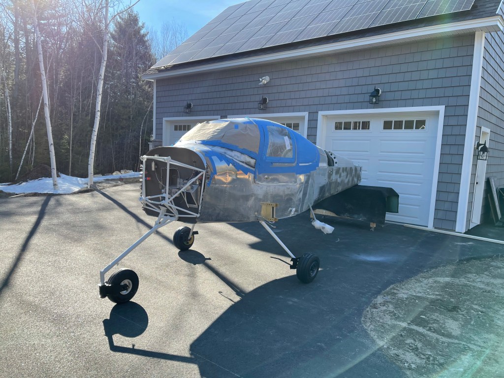
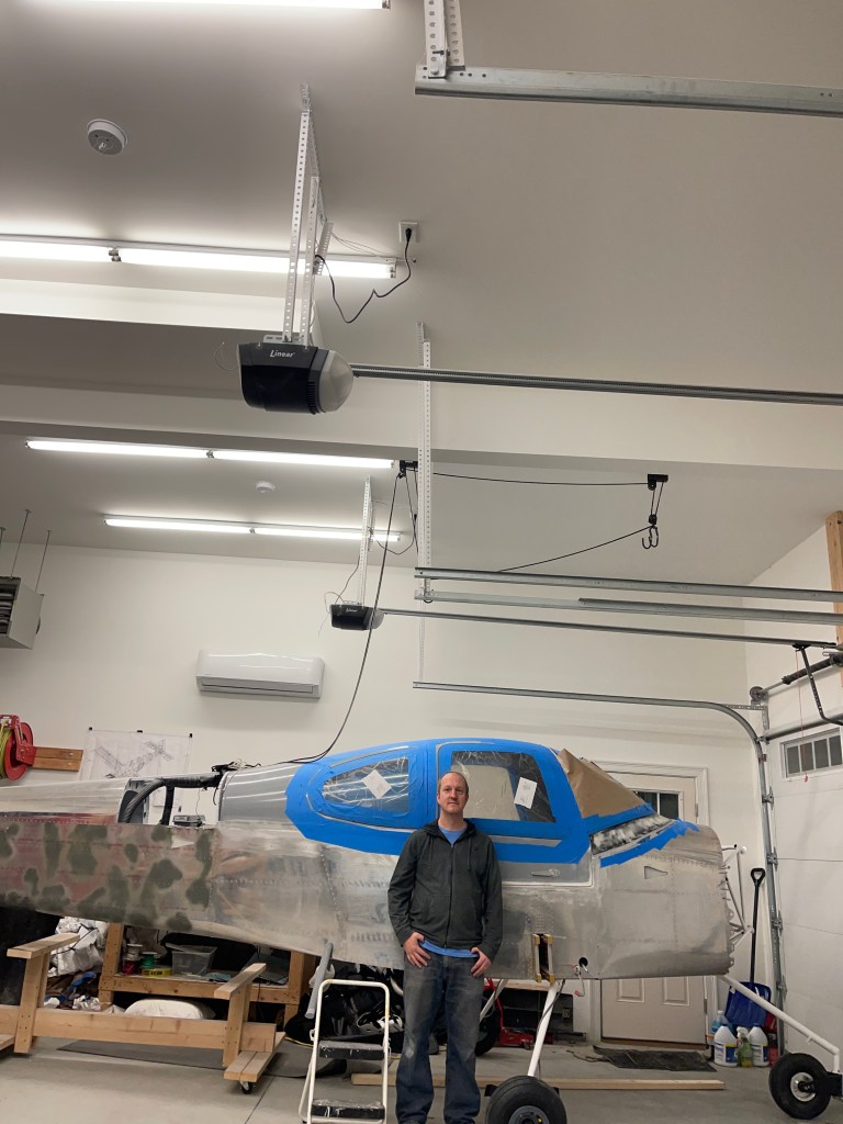
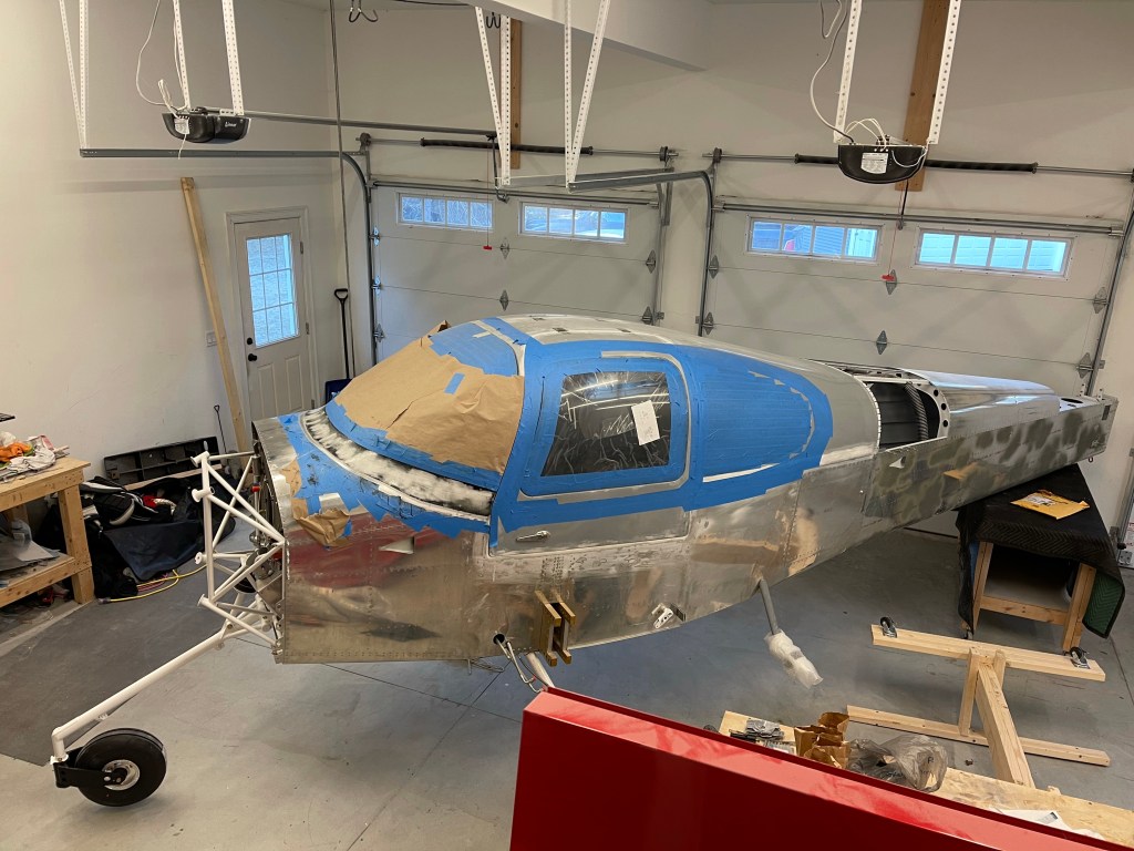
I then got the plane repositioned in my garage. It’s now kiddie cornered across 2 stalls so I have room for the engine to be mounted and still move around it.

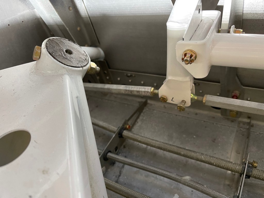
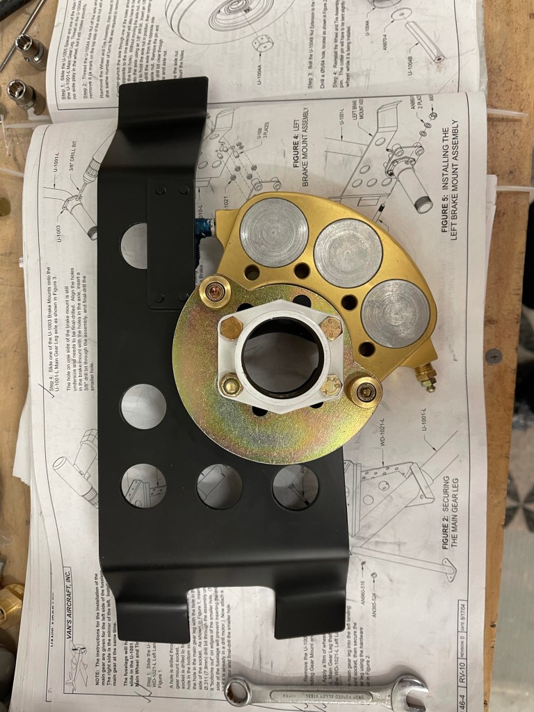
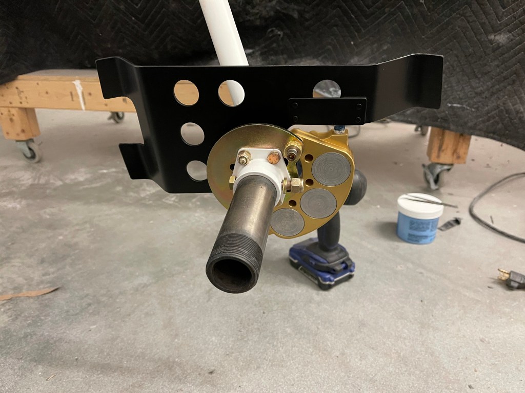
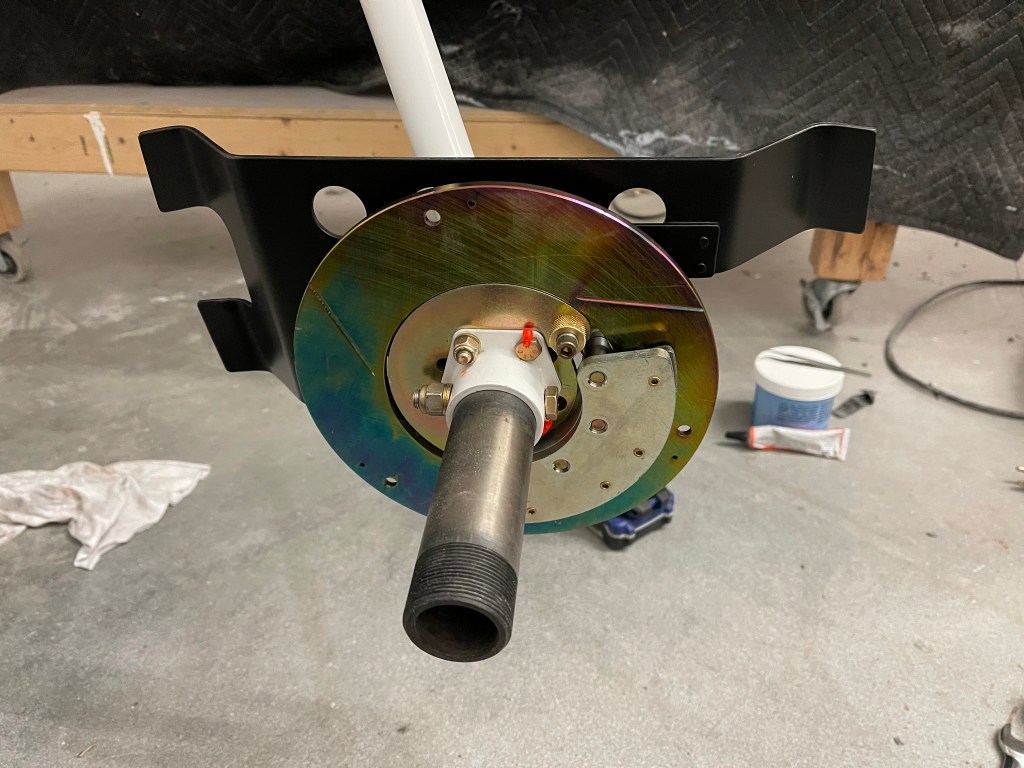
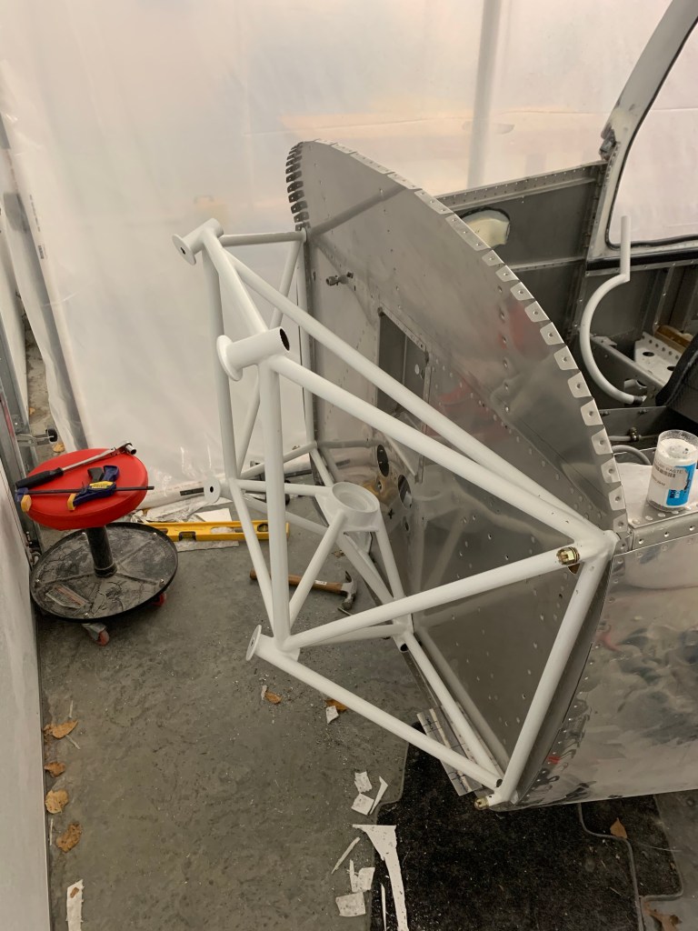
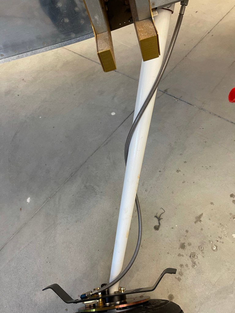
I also got the brake lines installed and taped to the gear legs.

Brake lines taped

While I’m waiting for my engine to arrive, I’m knocking off misc items still to do on my list.

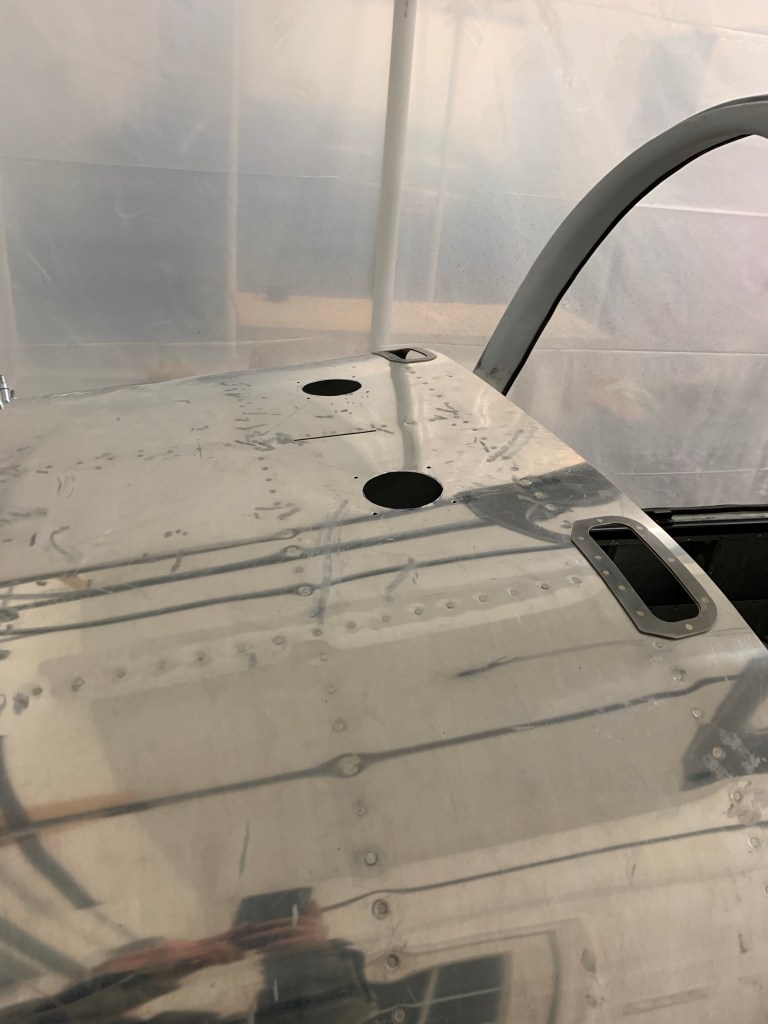
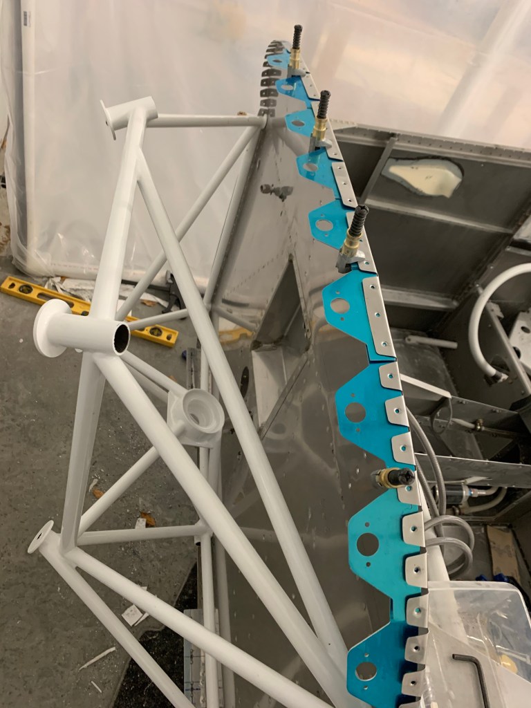
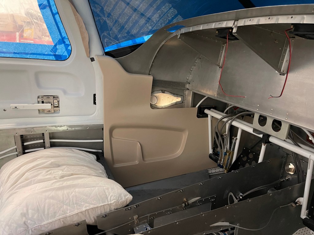
I started getting the interior side panels trimmed to be able to paint them. I started with the rear panels as they don’t require too much trimming. I did have some adjustments to do as I did build up the door areas a little more than stock, but the trimming wasn’t too bad.

Left rear and baggage door panels
Right rear panels

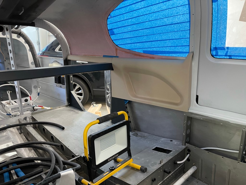
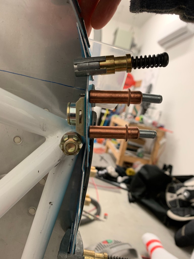
There are 4-5 screws that need to be located and nut plates added to hold the panels in place.

Then it was time to tackle the front panels. These require a bit more trimming, especially around the front door frame where I built things out a bit more with micro.

Front left panel in place

One trick I saw used was to use a compass scribe a line matching the contour of the area around the door frame. Trimming to that line, gives a good fit. This marking and trimming around the frame was done progressively until everything fit well. Taking a little off at a time is key here.

I then placed the instrument panel in place to make additional trims around the air vent area until it all fit well.

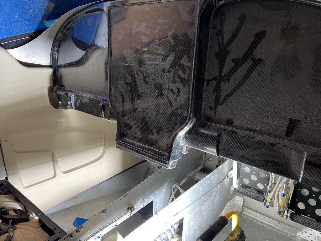
This process was repeated for the right side. I do have AC hoses routed down the right side, so I additionally had to trim the front of the panel to alleviate interference as the hoses leave the firewall and start their journey down the right side. I can now paint these when I have some time..

Up on the Gear!

A very late post of this content that I found in my drafts.. Apparently I started on this, but never finished/published it.. so I’m doing it now.

The wheel fairing brackets needed to be modified to accommodate the Matco brakes. The AN fitting for the brake line interferes so a section needed to be cut out as marked below.

I added an extra piece os .125″ material riveted on where the piece was cut out, but offset to allow a pocket for the brake line AN fitting to sit in.

The wheels were prepped and the tubes and tires placed on them.

All 3 tires and wheels done.

Then the plane was lifted up onto the table with the help of several friends and family. It was much heavier than anticipated. I utilized a 2×4 through the wing spar area for a person on either side. One person lifting the tail and another lifting at the firewall. Yet one more person to help position the table.

Now that the plane was up on a table, I could then slide the gear legs up into the weldments. I used some grease (same as the wheel bearing grease I have) on the legs to help get them into place. Once close, I used a curved pair of tweezers to feel the edge of the hole in the leg itself. I made small adjustments to get the hole in the weldment aligned perfectly with the gear leg hole. Once I could “feel” the inside of the hole all around without any misalignments between the two, I then reamed out the hole to final size.

Bolt and washer(s) and nut were installed..

Left gear leg installed.

After priming the gear fairing bracket, I continued assembling the Brake assembly per the Matco and Van’s instructions.

The initial brake assembly was put into place and the axle was drilled for a bolt (which was later turned the other way to avoid interference)

Rotor and other pad in place.

The wheel bearings were then packed with grease using this nifty tool from Amazon.

Then the wheel was installed on the axle.

Rather than oblonging the axle nut hole as depicted in the Macto instructions, I opted to drill a 2nd hole a little farther inboard as depicted below. The Van’s instructions were followed to count the number of turns required to remove the nut.. then the wheel/tire were removed and the nut added back the same number of turns. The axle was then matched drilled to the hole in the nut.

The assembly was then put back together and cotter pins added through the axle nut and the wheel fairing extension.


The same steps were repeated for the right side.

The nose wheel fork was prepped and primed.

The nosegear leg was then put into place.

Initial fit of the nose wheel in place.

The rubber donuts for the nosegay were put into place, but not compressed down yet

With all of that done, the plane was pushed off of the table and onto its own gear for the first time!!! Pictures below of it wheeled out into the driveway and back into the garage afterwards. For now, a table is used to hold up the tail until the engine is put on.

A Major milestone complete!!!

Odds and ends

Now that the doors are painted, it was time to put them back together, including the handles and associated racks.. I pulled out the safety wire and finalized the connection between this rod from the Planearound kit to the middle rack assembly. First was to safety wire around the body of the rod leaving plenty of length to the ends to pull through the door and the access hole in the door.

I fished the safety wire up through the hole with the help of needle nose pliers.

Then the wire is passed through the hole on the plane around pin that secures the rod to the rack (inside the door)

Pulling the ends of the wire causes the pin to slide downward and into the hole.

Pin pushed into the holes connecting the rod and rack.

Final step is to twist the wire, snip, and tuck the end into the inside of the door ensuring that it doesn’t snag up on anything while operating the hinges.

I then cut and sanded the Aerosport carbon fiber door sil covers. Reason for doing this now is I need to place the Planearound Cam blocks on the sil, and this will add a small amount of height. I also wanted to drill through this while match drilling the block to the door sil. As you may see below, I had to also cut out a notch from the micro that I had previously applied to get the cam block to sit completely on the sil and provide enough edge distance.

Door Sil Cap
A view of sil cap from across the plane

With that done, it allowed me to place the cam block on the sil, drill, and setup the cam location.

Cam and Cam Block on the left door.

I also spent some time cutting 3″ holes in the upper forward fuselage for defrost fans/avionics cooling.

Not that I didn’t know it was coming, but I’m quickly realizing that I’m moving into the expensive part of the build. Some recent goodies that showed up are the Mountain high 4ip oxygen system and my Aerosport 310 Instrument panel!

O2!
Instrument panel, side panels, and center console test fit.

I also placed a deposit on my engine build planned for April of 2021. Still hoping to go to Aerosport Power in Kamloops, BC Canada in April to build my engine with a tech for 3 days with their build school, but we shall see. Border is still closed with no opening in sight. I also ordered an Airflow systems Air Conditioning system to install as well. It will add some time and expense, but it’ll be worth it hauling the family around in the summer months and taking the edge off.

I then got to installing the engine mount by match drilling the holes and placing bolts in place as I went. One word of advise I saw from others was to start at the lower center holes and work upwards. This goes against the plans stating start at the top hole. The mount needed to be pulled outward a bit to match the center of the pre-drilled smaller holes in the firewall. All of the bottom holes aligned well from the start and allowed less stretching of the mount outward to get the hole drilled.

Engine mount temporarily mounted

With the engine mount in place, I set out to start working on the sky bolt 1/4 turn fastener install. Really just the flanges for now. The rest will come when I am fitting the cowl after the engine is hung. I chose to install the Skybolts around the entire perimeter of the Firewall. I’ll keep the hinge and pin for the top/bottom cowl split. I played around with placement of the flanges keeping in mind to avoid any interference with the engine mount and the sky bolt receptacle.

Avoiding interference with the engine mount sets the starting position at the top of the firewall