Continuing from where I left off. Wiring continued… Pulling wires to where they need to go. Cutting to length, stripping, crimping a pin on, and inserting into the connector.. Rinse.. Repeat! It’s always a fun time contorting myself </end sarcasm/> on the front seat area to get underneath the panel..
Working on some wiring behind/under the panel
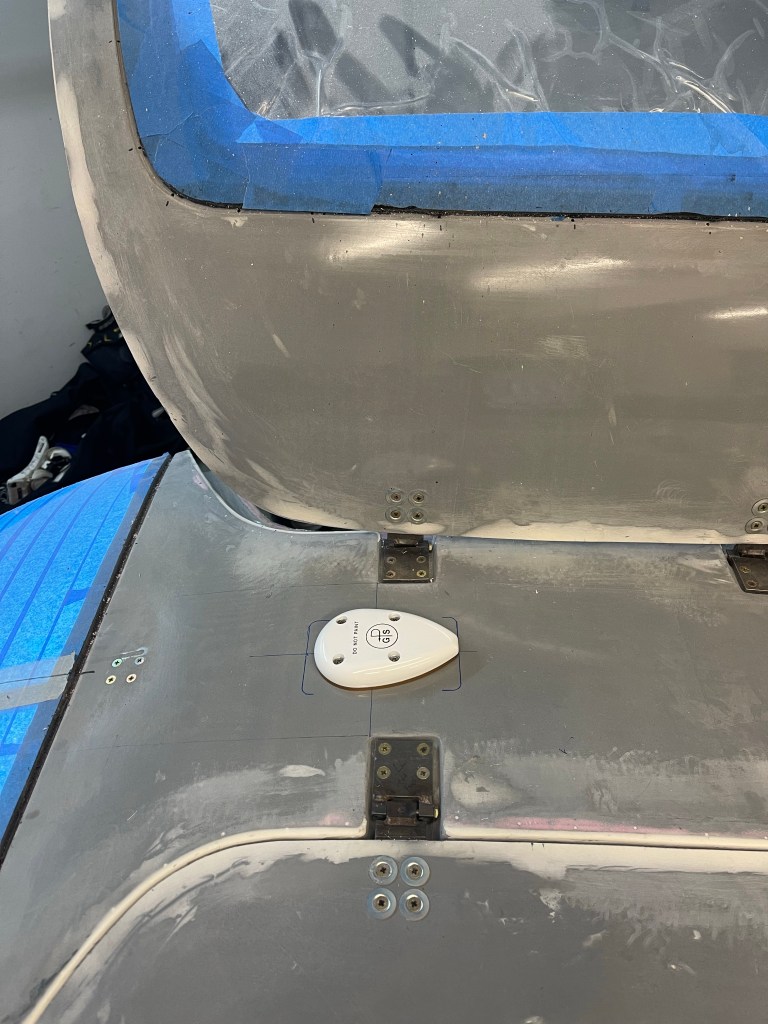
I got the remaining GPS antennas installed.
GA35 between the doors.
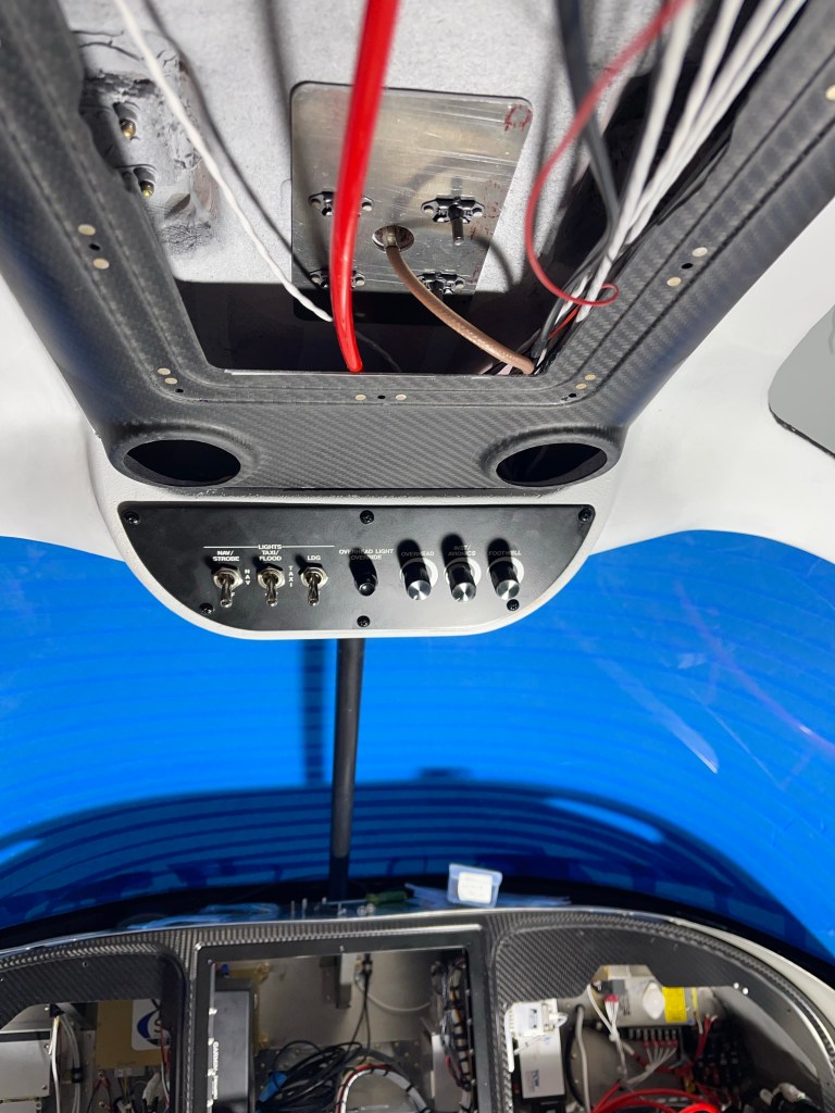
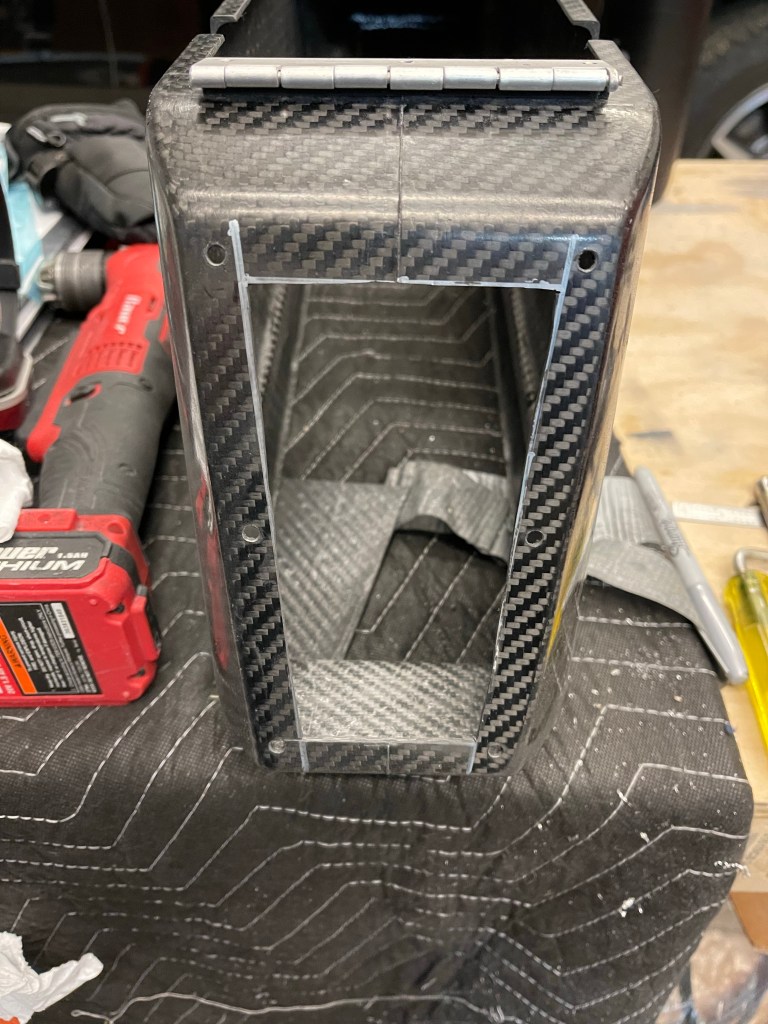
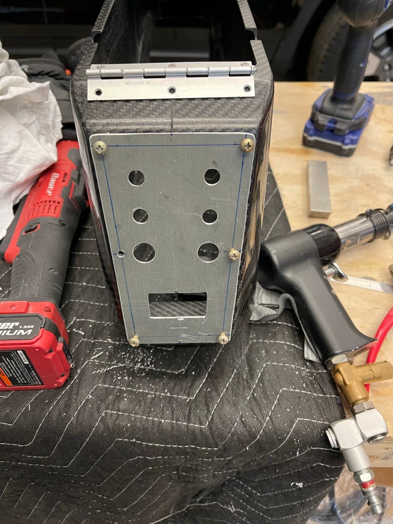
I also got the switchpod finished up and wired down the A-pillar conduit.
Closeup of switchpod
I installed the GA-57X on the aft metal portion of the airframe. Just behind the AC evaporator to avoid interference.
Inside view of XM/GPS antennaOutside view of the GPS antenna
One other thing I wanted to do before closing up the panel was to put the leather glareshield material in place with the two GPS pucks mounted on top of it. Below you can see me getting it lined up properly and the final product.
Getting the material alignedWider view of it all done and tucked under/between the glareshield overhang and the carbon panel.Closeup to see the detailed stitching. Also a defrost fan grate in place.
I then installed the Pitot static and AOA tubing, distributor blocks, and connected them up to the G5, GSU25’s and the alt static switch. I then mounted all the avionics back into place in the panel.
I also decided to pin out the harness that will go out in the right wing. It houses the roll servo and magnetometer. Without it the CAN bus wouldn’t have been terminated properly and communication errors would have happened. I have those things laying in the footwell for now. I’ll have to depin from the CPC connectors later to route the harness through the wings, but that’s easy enough.
A number of triple checks to make sure I didn’t see any shorts between power and ground and making sure +12V was connected to the + side of the battery and negative to negative.. The moment of truth came…..
The panel powered up and everything seems to be working!!! A bunch of wiring work to get to this point, and it represents another major milestone in my build.
I really can’t say enough about the work that Aerotronics did to build this panel. They make it really easy to put it all together.
Now on to pushing forward and getting the remaining pieces finished up so I can get this bird to the airport and signed off to fly!
Not too many updates recently. I’m at a point where it gets harder to take meaningful pictures. So here’s a photo dump of some of the more significant updates over the last couple months
I worked on finishing up the forward tunnel by wiring the fuel pumps and getting the transponder antenna doubler installed with the help of a fellow builder. I then got the cover on and secured the throttle and prop cables and some wire bundles for the headsets in the center console.
I cut out the rear portion of the arm rest where the jacks for the rear passengers and a USB charging port.
The metal plate to cover up the hole I cut and house the jacks.
I also cut holes out in the plastic insert in the arm rest for headset jacks for front passengers.
Jacks installed.
I also installed the 2 GPS pucks on the glare shield in front of the defrost fans.
Left side of the panel area.
Lots of the panel is connected to the rest of the airplane with CPC connectors. Here, I am wiring the P1 connector which houses things like the master contactor switch, starter relay, alternator regulator connections, flap motor connections, fuel senders, door sensors, pitot heat, and boost fan for the AC.
P1 wiring complete.
Secured into place with a clamp.
Wiring like the P1 wiring will continue.. Next post will likely be when I get to the point of powering up the panel for the first time.
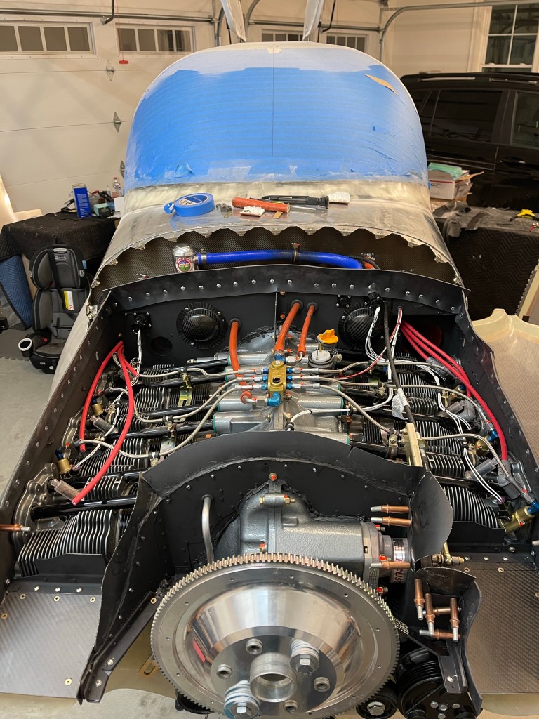
Wow.. What a ton of work! I’ve now completed all the Firewall Forward plumbing and wiring. The only thing left to do is to put spark plug ends on the wires and maybe tidy up a couple of wires, but outside of that.. I’m done. I also took a little extra time to revisit my baffle material seeing I wasn’t completely happy with it the first time. I changed the left, right, and aft material so each was one contiguous piece of material. Previously they were broken into 3 pieces. The aft part had some puckering that I didn’t like as well, so was addressed with this update.
The next couple of pics are from the front.
The right side of the engine.
Boy does it really get busy in the space between the firewall and the engine. Especially when you have 2 coil packs for the spark plugs.
The left side of the engine.
Again busy busy.. It really took so much time not only to wire things, but to come up with reasonable routes and securing things.
Now its back to finishing the inside wiring and getting my panel powered up!
Mostly been focused on FWF wiring. There are lots of connections to be made and properly securing the wires seems to take considerable time. Fabricating brackets.. etc..
Below you can see the metal L brackets I made along with a short straight metal piece to secure the #2 starter cable to the oil sump. The straight metal piece allowed me to mount the adel clamp for the #2 wire inwards, sort of on top of the sump. The adel clamps down lower allow for the lower voltage signal wires, mainly CHT and EGT, but also throttle position sensor wires to be secured.
Left side brackets
I also secured the AC hoses FWF along with putting the ends on the compressor side of the hoses. I secured the hoses to the forward-most intake tube, a plate secured to the left side of the cold air sump.
Left side AC hoses
The hoses connected to the FW and secured (although not in sight) to another metal bracket attached to the bottom of the cold air sump. I may also secure them to the engine mount in the middle of the run shown below.
Right side AC hosesAC hoses ready to be connected to the compressor
CHT probes were screwed into their locations in each cylinder. I then got to locating the EGT probes making sure they have clearance seeing they stick straight out of the exhaust pipe. I targeted 2 1/4″ down from the flange. I was able to locate 2 of the 3 on the inside of the pipes and #2 needed to be pointed outside due to the angle of the pipe and the heat muff being on this pipe giving few other options.
Drilling a hole for the EGT probeProbe secured in placeLeft 3 pipes have EGT probes installed. Left side coming along
I’ve run spark plug wires to their destinations. The left coil pack services the top set of plugs and the right coil pack services the bottom plugs on each cylinder.
Top Right spark plug wires routed. Top Left Spark plug wires routed.
At this point the left side is just about complete. Still need to finish the spark plug wires and the Tanis wiring to each cylinder heat element. Time to work on the right side.
Left side nearing completion.
Below are some other pics of having a bung welded into the right side exhaust collector for the SDS O2 sensor installation spot. I had a local guy TIG weld this on for me.
O2 sensor bung.
I also split the forward tunnel cover into 2 pieces like most builders do with an Aerosport center armrest/console. I also mounted my bracket for the throttle and prop cables.
In unrelated news.. I received my Aveo Engineering Zip Tip wing tip light units. I ordered these at Oshkosh, so 6-8 weeks turned into 6 months wait time, but they are here and they look great!
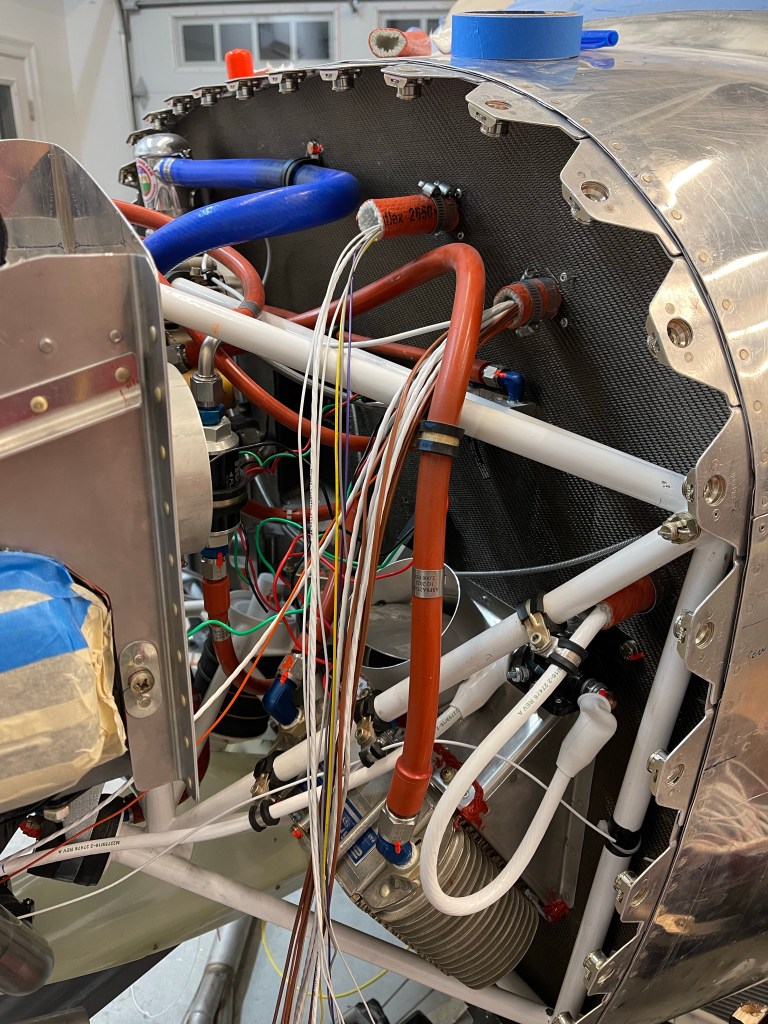
Most of my time recently has been getting all the wiring for the Firewall forward needs out through my firewall passthroughs and in a position to hook up.
This has largely been things coming from the Garmin GEA-24 and the SDS EFII ECUs.
Pilots side wires needing connectionCo-Pilots side wires needing connection.
On the co-pilots side, the main bus feed was brought from the primary alternator through a 60A ANL to the fuse blocks on the right side of the subpanel.
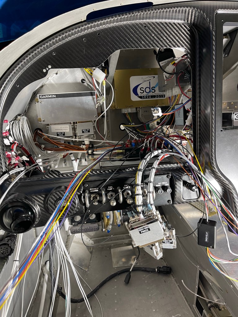
The left (pilots) side is mostly the GEA-24 (on the left) which has wires for cylinder head temps, exhaust gas temps, and various fuel, oil, and manifold pressure sensors.
Along with the SDS ECU box which has connections to the manifold pressure sensors, Cylinder head temps, airflow temps, wideband O2 sensor for air fuel ratio measurements, and injector power and ground wiring.
Also Coil pack wiring. This thing needs a lot of connections.
Lots of Spaghetti on the left side still to be cleaned up.
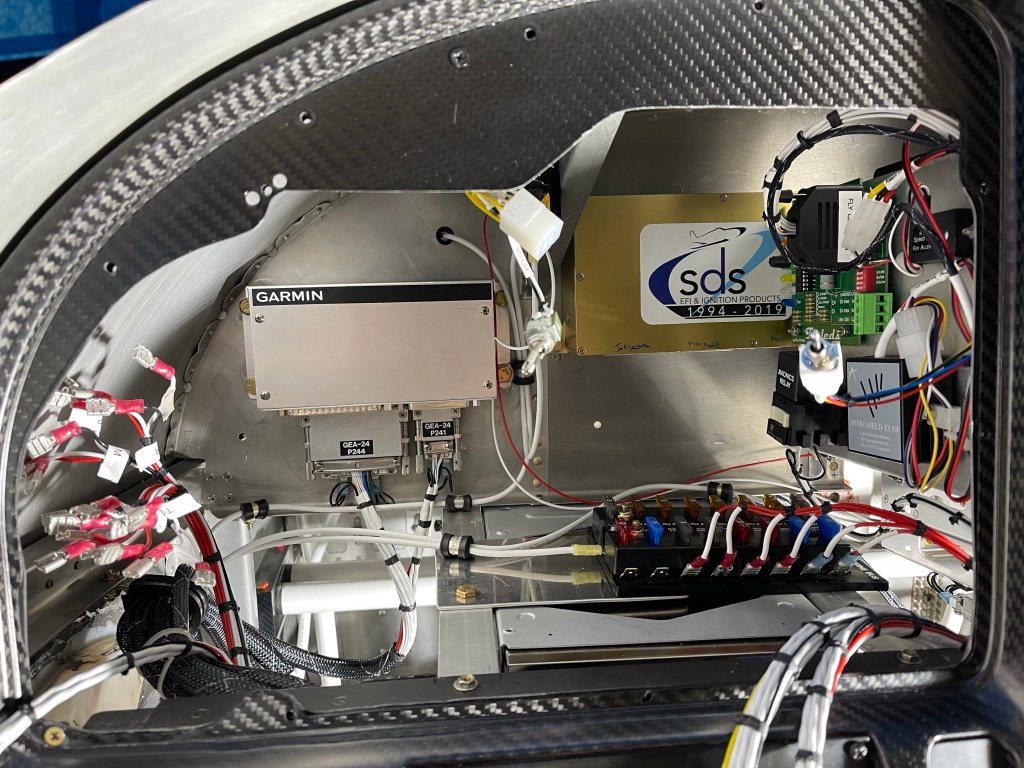
And finally, an overview picture of the panel so far.
I decided to send my Mountain High bottle back to take the regulator off of the bottle (shown on the bottle below) so I could remote mount the regulator. That will give me the option to take the tank out and get it filled at a shop somewhere. I chose to copy Joe Keys’ installation and mount the bottle to the right side behind the baggage bulkhead. I used an ELT mount along with some angle and flat 1/8″ stock aluminum bar. The angles were mounted to the J stiffeners and I used one hole of the ELT mount for attaching the mounting brackets. It’s hard to see in the pictures, but I used 1/8″ flat aluminum bar between the bottle mounting bracket and the angle/ELT mount to Secure to extend as far as I needed to and attach to the structure.
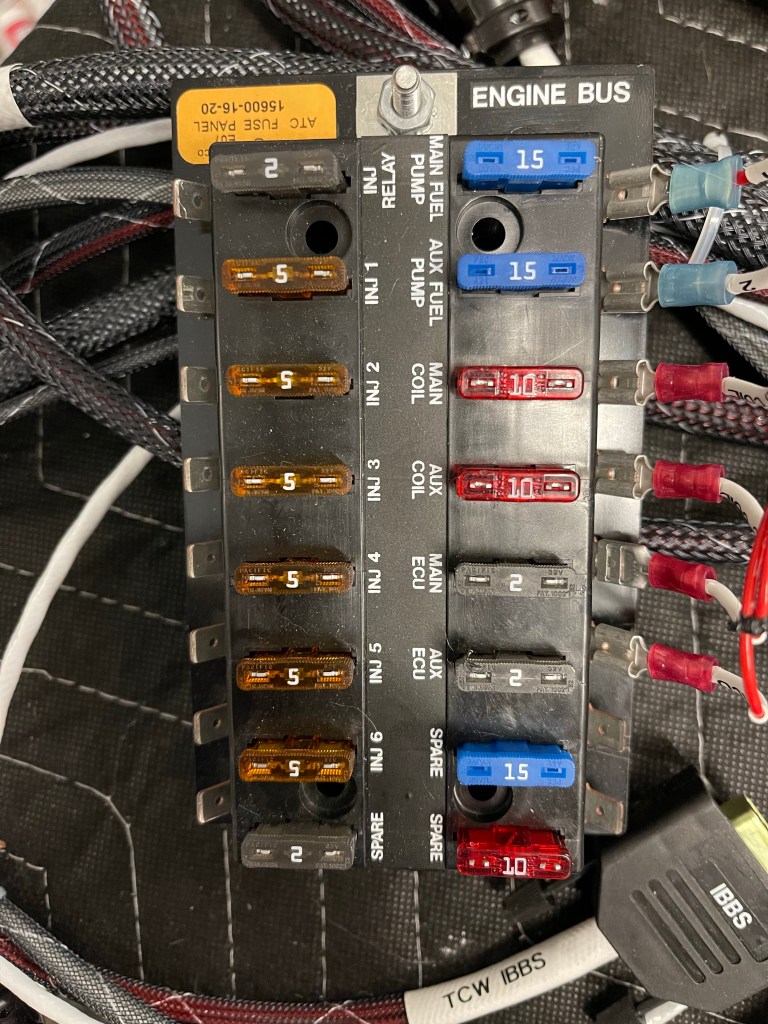
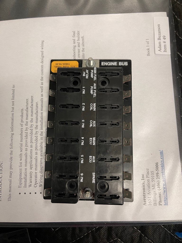
In somewhat of a paranoid redundancy of my engine bus move, I decided to modify the fuse block to add a 2nd stud. The unit has a spot (both a hole and an indent in the plastic) for a 2nd stud.. it’s just not exposed. Below is a picture of the fuse block as it came to me.
I popped the top open and inserted a second stud and then drilled the plastic to expose the stud and be able to tighten down the nut. This will allow me to have the 2 separate feeds of the engine bus connect to different locations protecting against a nut coming loose or something breaking from removing power from the fuse block.
Fuse block modified for 2 studs.
I then moved on to more AC work. I got the skinnier return ducts from Bill and installed them. This moves the whole evaporator forward to give more clearance to the J stiffeners on the top.
Skinnier return ducts installed.
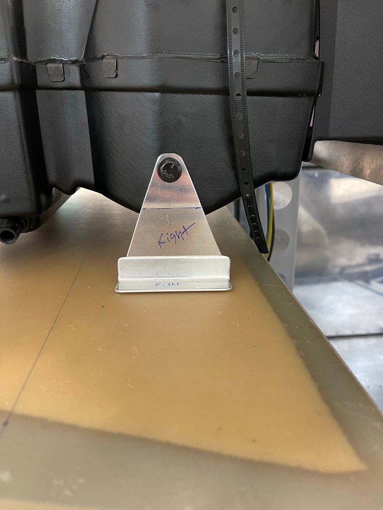
With those installed, I positioned the evaporator, and fabricated new forward brackets with an angle and some scrap metal, seeing it sat much higher than the bracket provided to me and they didn’t reach the shelf. This was a suggestion from Bill.
Fabricating new forward brackets
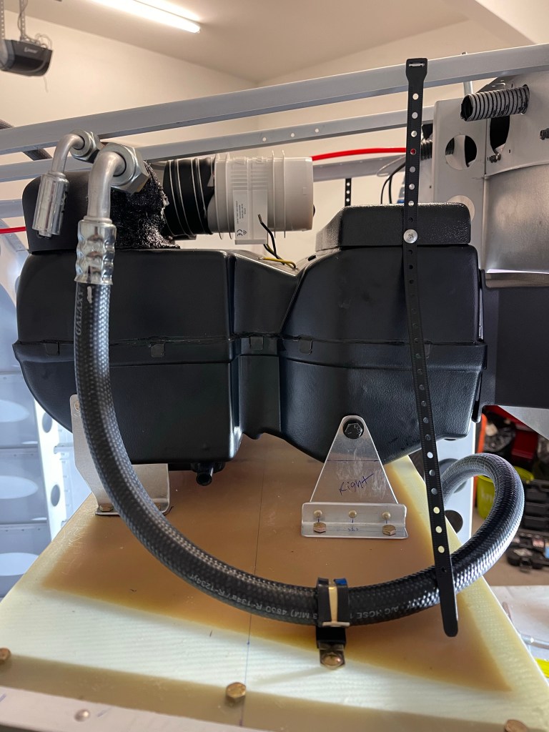
I spent some additional time routing the hoses to the evaporator unit with the service ports easily accessible by taking the lower baggage bulkhead off.
AC hose routing to evaporatorAC hose runs with service ports shown. Hose to the dryer unit.
Then it was on to antennas.. More in the category of finishing electrical runs out to the tailcone. One of the things I had yet to finish was mounting the NAV antenna on top of the Vertical Stabilizer. I fabricated a doubler plate and drilled holes in the skins at an angle to accept the cat whiskers.
I sanded down a long wooden dowel to a point in order to insert nutplates up into the VS to hold the antenna puck in place. I’ve also seen people use a rod threaded for the 10-32 nutplate as well, but this worked okay too.
NAV antenna in place.
ELT antenna was next. A lot of builders try to mount this inside under the fiberglass. Some DAR’s, including the one I’m using, want to see this external to the airplane.. so I decided to just bite the bullet and put it just forward of the Vertical Stabilizer. I fabricated a doubler, riveted it to the skin, and mounted the antenna in place.
ELT antenna.
I also utilized another ELT mount on the left side to mount the diode with it’s heatsink and the Battery Bus relay. Shown just below and aft of the ELT.
Then it was lots of panel wiring. I first got the remote transponder mounted on the left side with some angles added front to back.
Remote Transponder mounted.
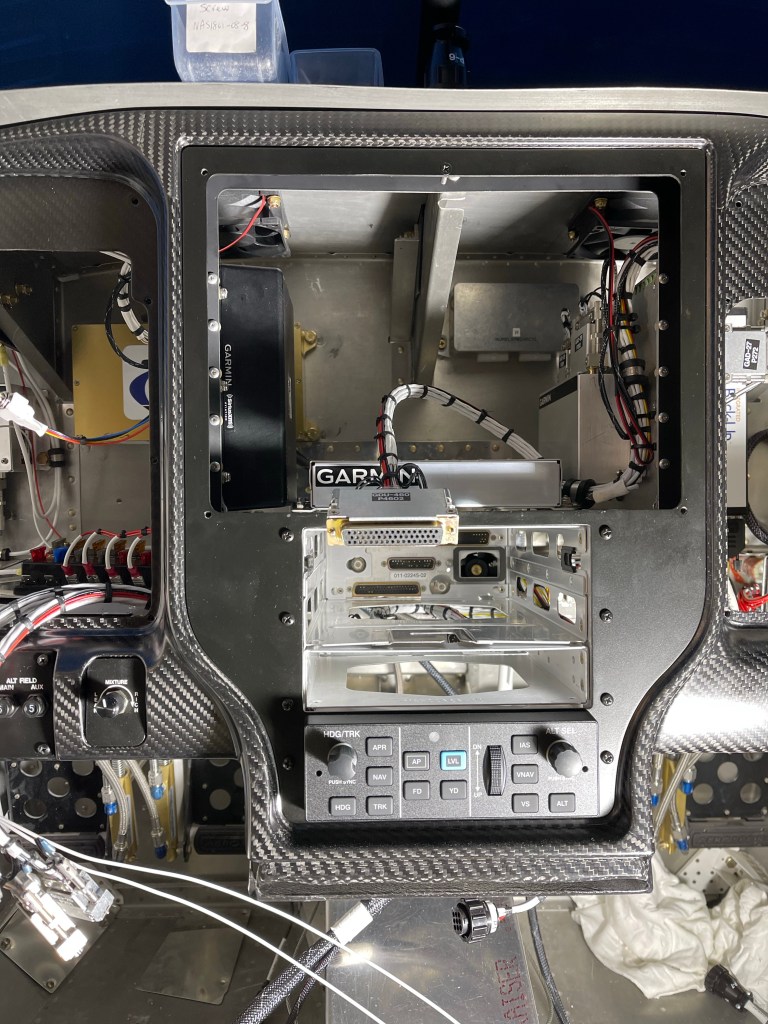
I mounted all the needed components not already on the avionics shelves to the sub panel shown below.
Subpanel components mounted.
I then put the metal panel frame and outer panel back in place and got the wiring harness re-attached to all the switches etc..
Panel wiring stats now!
A bunch of time was spent locating the fuse blocks and getting the basic power connections hooked up. Still lots to do, but this is a snapshot of where I am today. Left side, right side, and center of the panel.
Pilots side. Engine bus fuse block is here… mounted on top of the transponder.Co-pilots side. Fuse blocks were the bulk of the work so far on this side. Center part of panel. Not much going on here.. I did wire up my defrost fans..
We take a brief pause in cowling related posts to show the finalized panel layout. Aerotronics is off and working on this and I should take delivery by the end of the year.
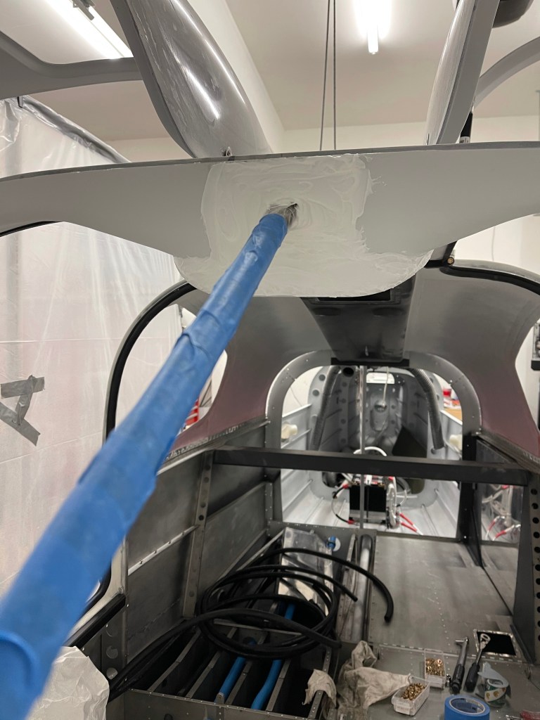
Now that the center support bar is in, it was time to finish the front of the cabin top to glass it in. I started by taking some scrap fiberglass pieces from the Aerosport headliner carrier material and drilling a couple of holes to hold things down with clecos. I then mixed up some epoxy and thickened it with Cabo so it wouldn’t run all over the place. This was left overnight to cure.
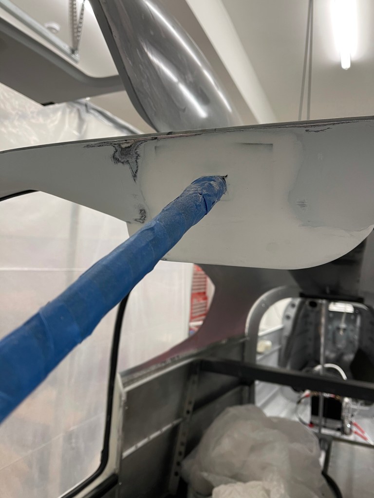
Once cured, a quick sand and then application of micro. Again wait overnight to cure.
Then began the sanding process to get it to be as flat as possible and also blend into the surrounding surfaces that I had already finished.
Once I was satisfied, I filled in a couple of divots with glazing compound, sanded, and applied a skim coat of epoxy with a squeegee and foam roller. That was left overnight, lightly sanded and then painting started. I followed the same process as the cabin top where I sprayed black DPLF primer, cleaned the gun, then shot K36 high-build primer. Just one coat was needed. After that dried, I sanded with 400 grit and cleaned prepping for topcoat paint.
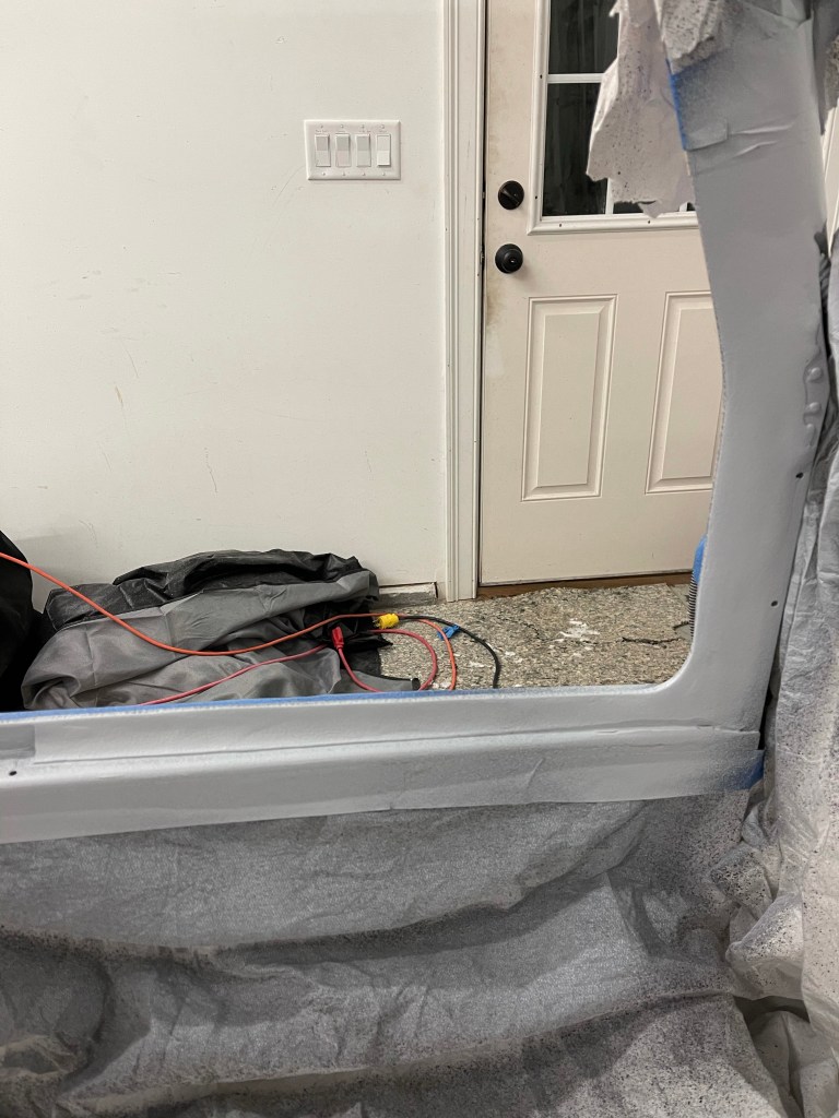
K36 primerLeft lower door frame.All the masking to catch overspray.
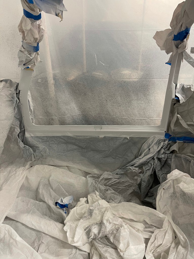
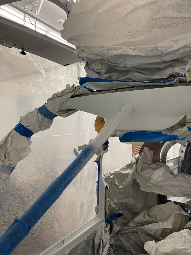
Then it was time to apply the omni sealer, top coat (Oxford White), finsishing with a matte clear coat. I donned my fresh air breathing hood and matching bunny suit due to the toxic nature of these paints. I applied the omni sealer, waited the time required to dry, followed by 4 coats of paint. Once dried, I applied the clear coat and let it cure overnight.
Masking all removed after cure
Lower door frames are not as perfect as the rest of the cabin top, but also there will be the McMaster door seal sitting here too, so not as much surface area will be exposed.
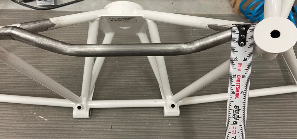
I had previously mentioned that I needed to modify my engine mount to accommodate the Barrett Cold Air Induction. I sought out a local welder and dropped it off for him to cut the existing bar out and replace with this curved one proving more clearance. I was never able to get an exact number on how much clearance was needed. I was mostly directed to leave about 1″ from the existing weld on each side and cut the new bar provided down to meet up and weld together. My welder was able to leave a little less than an inch from the weld on each side, which left approx. an inch of clearance, which should be more than enough. Now to prime/paint the exposed steel.
Initially, I had crimped some of my battery wires with a hex die hydraulic crimping tool. I was told by the supplier through ACS that that is not correct method for the terminals I had bought. I then decided to buy the crimping tool that Stein sells along with the terminals they sell as well to re-do everything I had already done. I don’t want any flakiness in the battery connections, so re-doing was simply the correct thing to do.
Test Crimp with new crimperRear battery connections complete!A view from the other side.
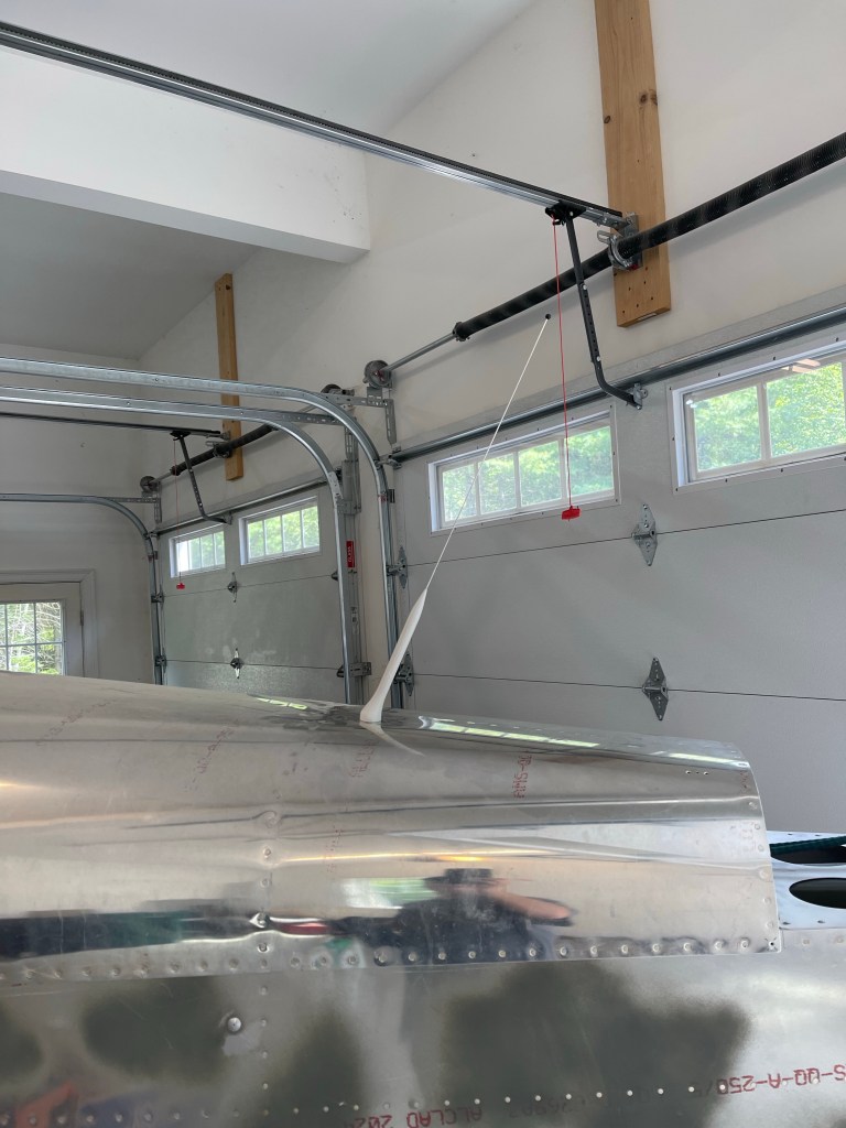
A side view of the plane as it stands. I’m just now starting to work on window installation using Silpruf. More details to come on that method.
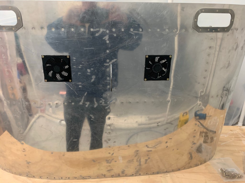
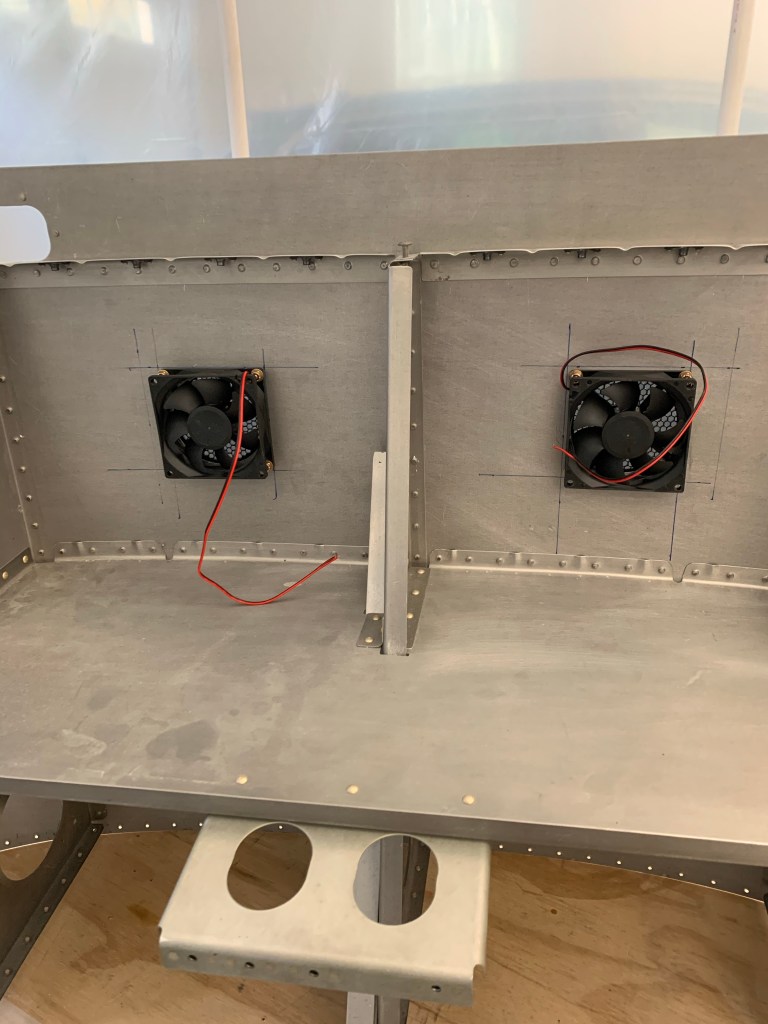
I’ve been knocking off lots of tasks here there and everywhere lately. I got the defrost fans and their plates installed. Below are views from the top and bottom side.
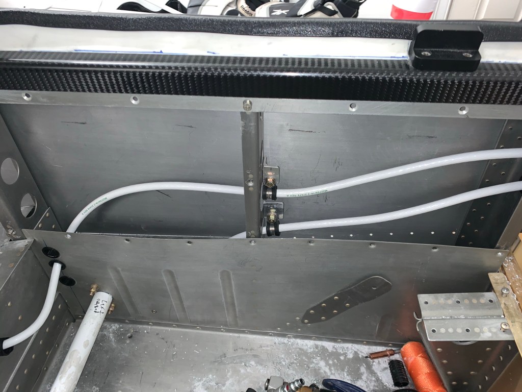
While waiting for some additional firewall items to arrive, I started pulling some #2 fat wire, 1 for each battery from the tailcone to the firewall. I fished the wire through the previously installed conduit
Wires poking out in the rear seat area.
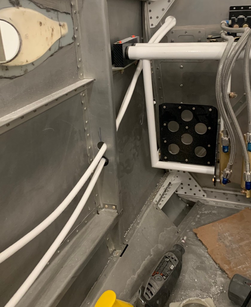
A bunch of work getting Adel clamps, drilling holes for bushings and routing the wires down the left side of the plane.
Adel clamp down inside the side wall below flap tube
I added some Adel clamps around the 2 larger lighting holes with some caterpillar grommet around the holes for extra protection. The wires end up away from the edges of the holes, but I want to be sure these runs are solid.
Adel clamps around 2 large lightning holesMaking their way forward.
I also took the time to install the spring and collars on the brake cylinders. I’ve heard that if the rudder assembly isn’t 100% square, that some binding can take place and cause the brakes to stay slightly engaged. These will help ensure that they always return all the way out ones your feet are off the brakes.
Springs and collars on Brake cylinders
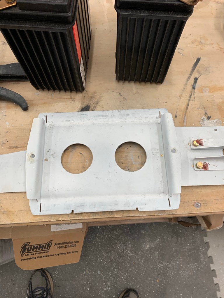
I then got to modifying the stock battery box. It needed some slight modifications to support two batteries. I decided to see if I could bend the sides downward to gain more space left and right. It seemed to work, and was a pretty close fit in the end. I’m glad I went this route, rather than cutting the sides off.
Left and right sides bent flat.Battery length seems to be almost perfect
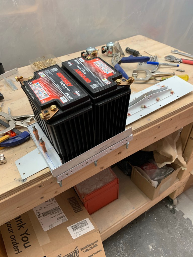
I then used some angle stock to retain the battery on the left and right. I also added an angle on the forward side to eat up an approx 1/4″ gap. Another angle was used on the left side below the whole assembly to house the battery contactors. You can see the holes for AN4 nut plates ready to go.
Angles all in place holding batteries tightInstallation all done with contactors installed.
I then installed a ELT/Strobe bracket between the J-channels of the tailcone that I had on hand from Van’s to house a couple of fuse blocks. These will be the main and aux battery bus hubs for all things related to my EFII installation.
Battery Bus fuse blocks installed.
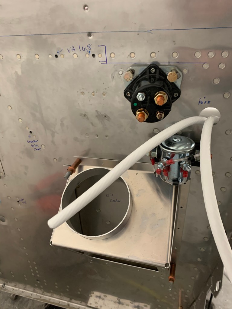
Then it was time to go back and work on mounting the firewall related items. I’m doing all of this prior to installing insulation of the engine side of the firewall. I want to have as many of the passthroughs and holes/nutplates setup as possible before I do this. I mounted the cross-feed contactor in the stock location for the starter solenoid, and mounted the starter solenoid just above and to the right of it.
X-feed contactor and starter solenoid
I also go the ground block (forrest of tabs) installed. This is a kit that has 24 grounds on the engine side and 48 grounds on the cabin side of the firewall. This will be the central point of all grounds.
I’m now working on Installing a couple of ANL bases between the alternators and the main/aux busses on the firewall. I’ve also ordered the AntiSplat aero Air/Oil separator and will be locating that on the firewall too. My air conditioning unit should be shipping soon so I’ll likely hold off a bit longer to drill holes for the 2 hoses that have to pass through the firewall too. Once I get to a point where I’m mostly comfortable with the firewall the path forward will be as follows:
Install upper forward fuse permanently.
Finish installing what I can of the Skybolt flanges.
Install firewall insulation.
Install support bar in center of windscreen area.
Finish fiberglass area around support bar.
Paint remaining areas of fiberglass around support bar and lower door area.
Install windows
Plane up on gear!!!
I hope to have all of this done before I have my engine in April/May timeframe.
After a bunch of back and forth with Aerotronics, we have a first pass rendering of the instrument panel. They have been absolutely great to work with thus far.