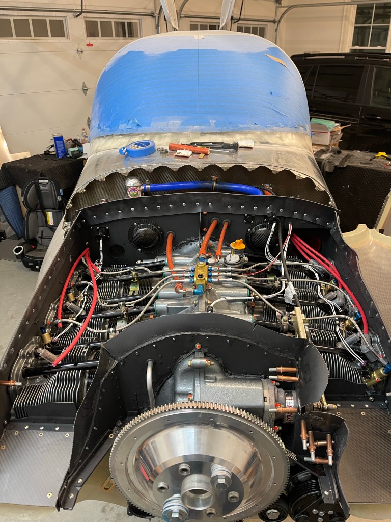
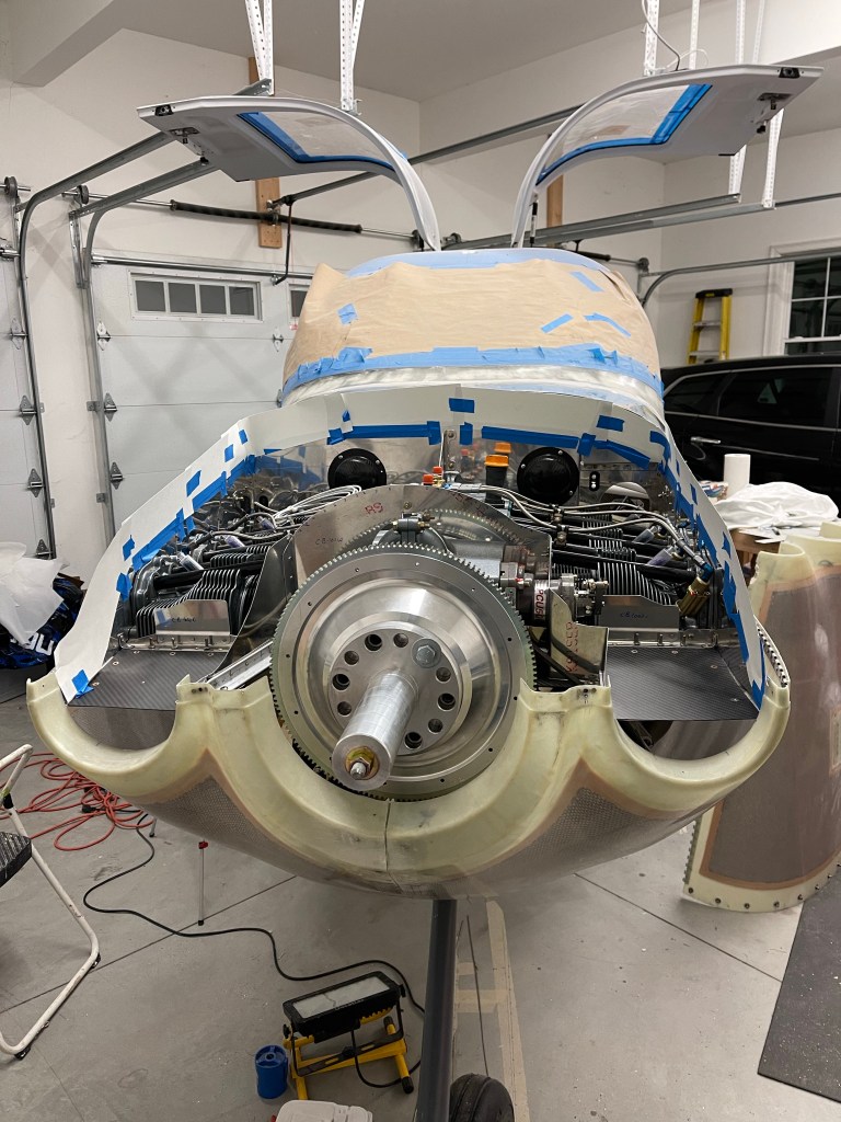
Wow.. What a ton of work! I’ve now completed all the Firewall Forward plumbing and wiring. The only thing left to do is to put spark plug ends on the wires and maybe tidy up a couple of wires, but outside of that.. I’m done. I also took a little extra time to revisit my baffle material seeing I wasn’t completely happy with it the first time. I changed the left, right, and aft material so each was one contiguous piece of material. Previously they were broken into 3 pieces. The aft part had some puckering that I didn’t like as well, so was addressed with this update.
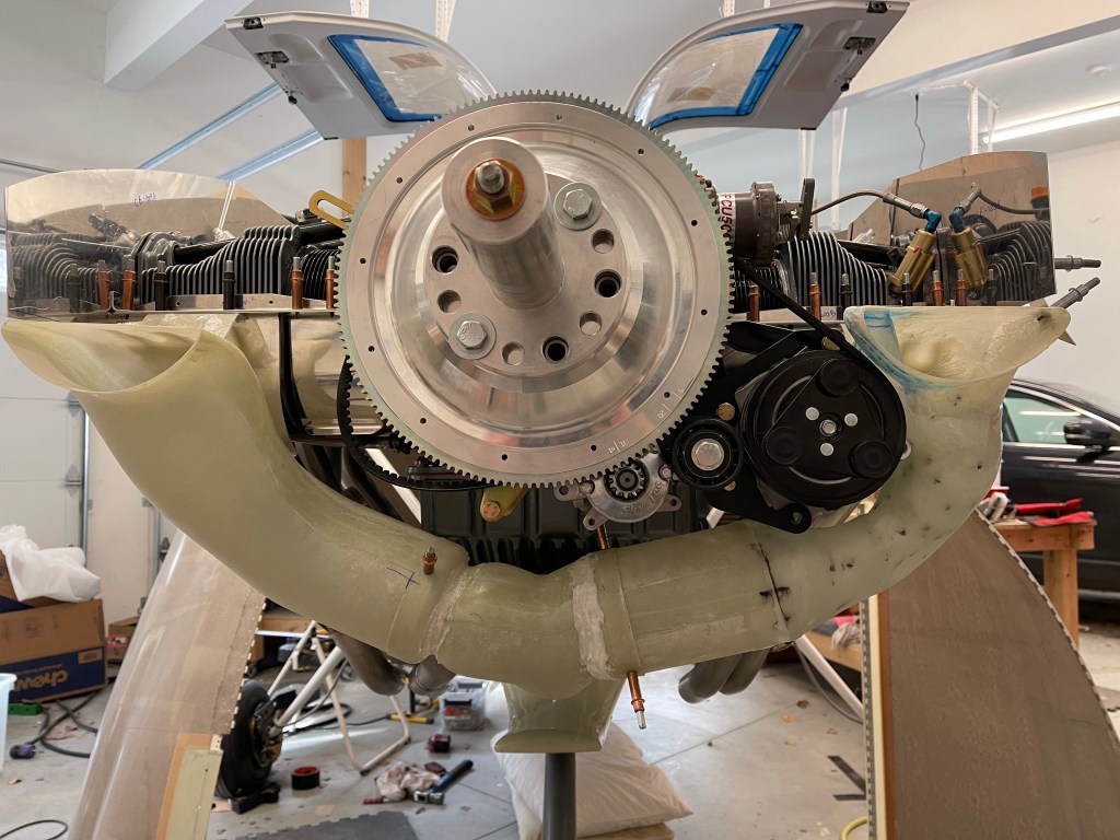
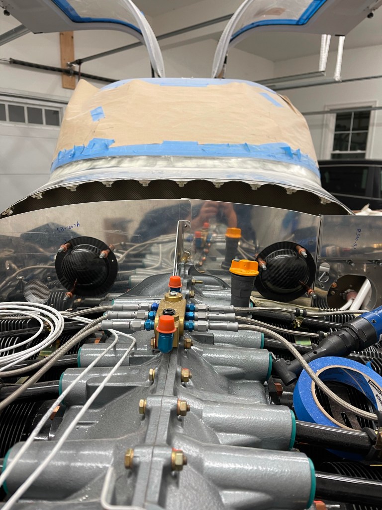
The next couple of pics are from the front.
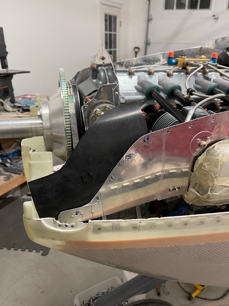
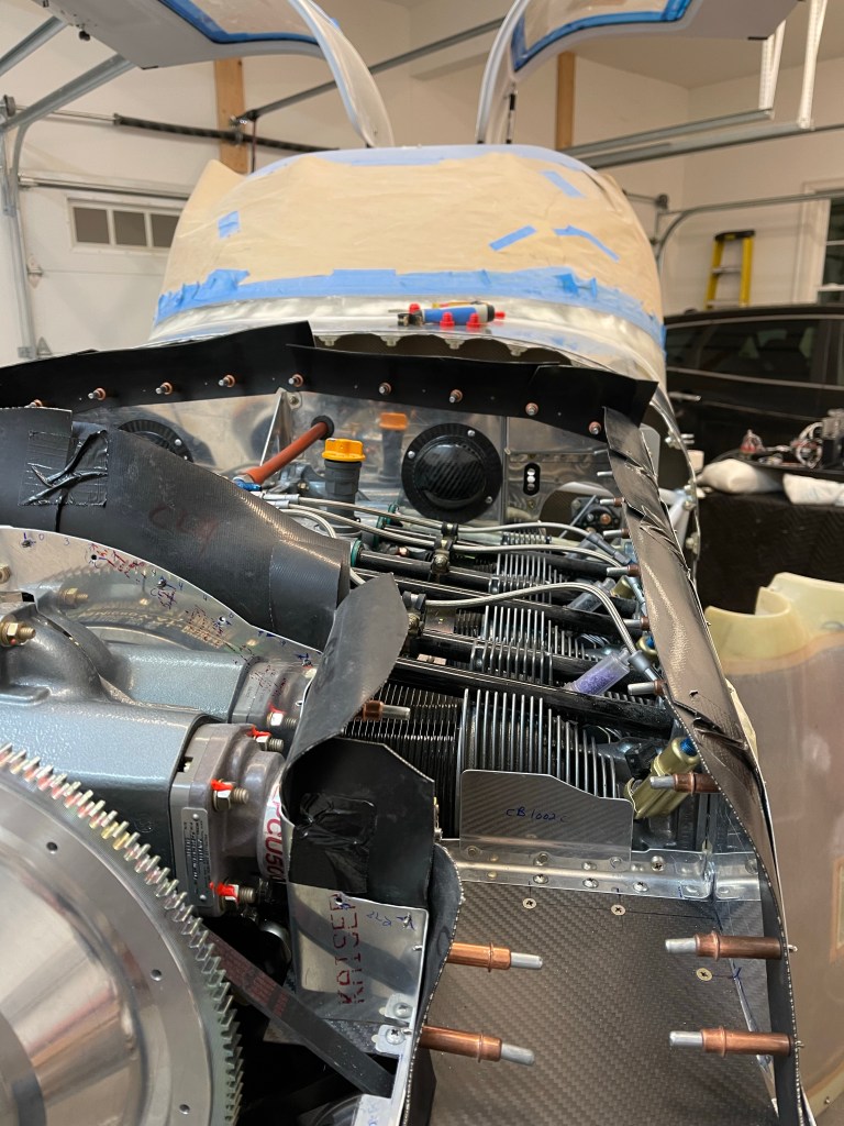
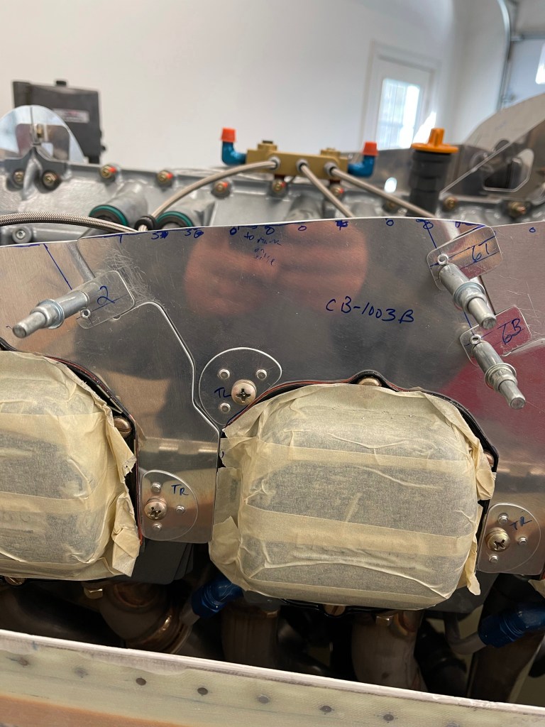
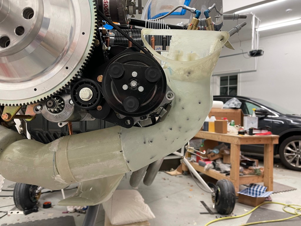
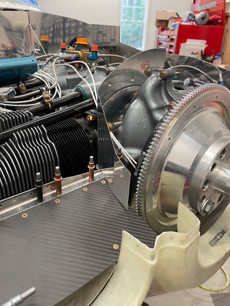
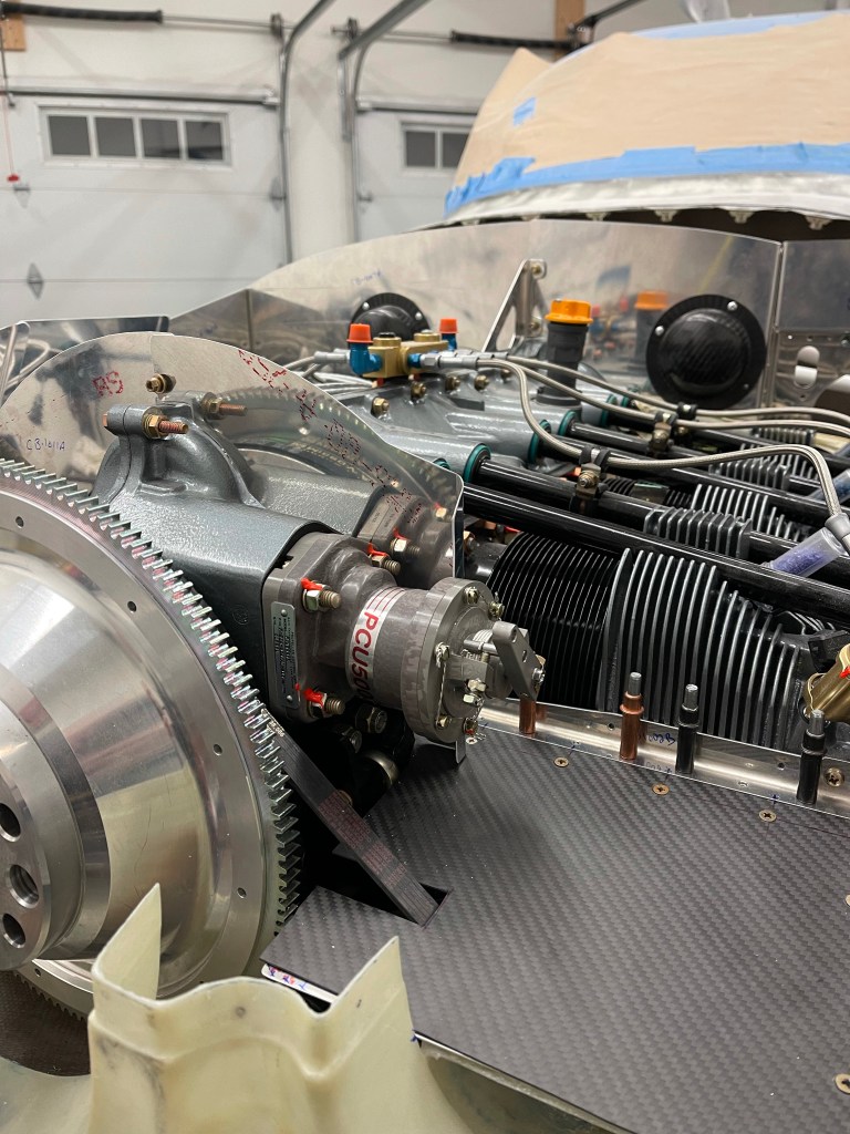
The right side of the engine.
Boy does it really get busy in the space between the firewall and the engine. Especially when you have 2 coil packs for the spark plugs.
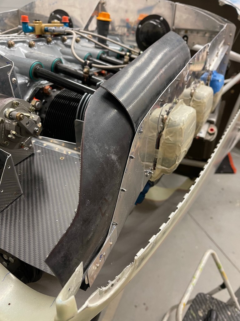
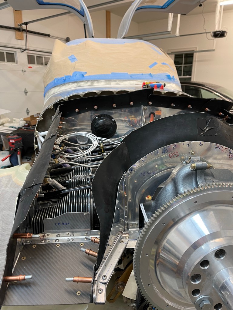
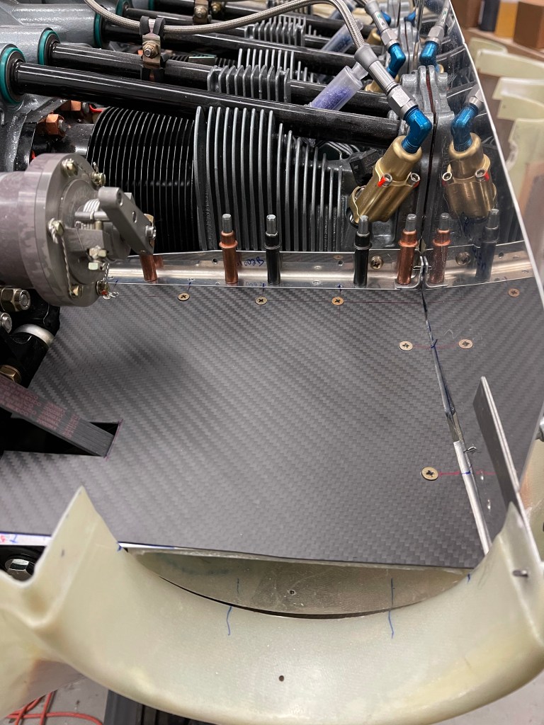
The left side of the engine.
Again busy busy.. It really took so much time not only to wire things, but to come up with reasonable routes and securing things.
Now its back to finishing the inside wiring and getting my panel powered up!
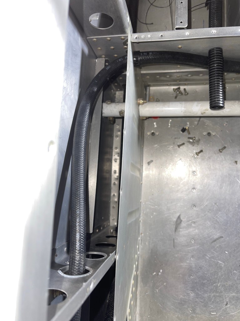
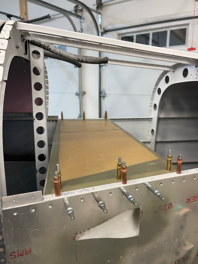
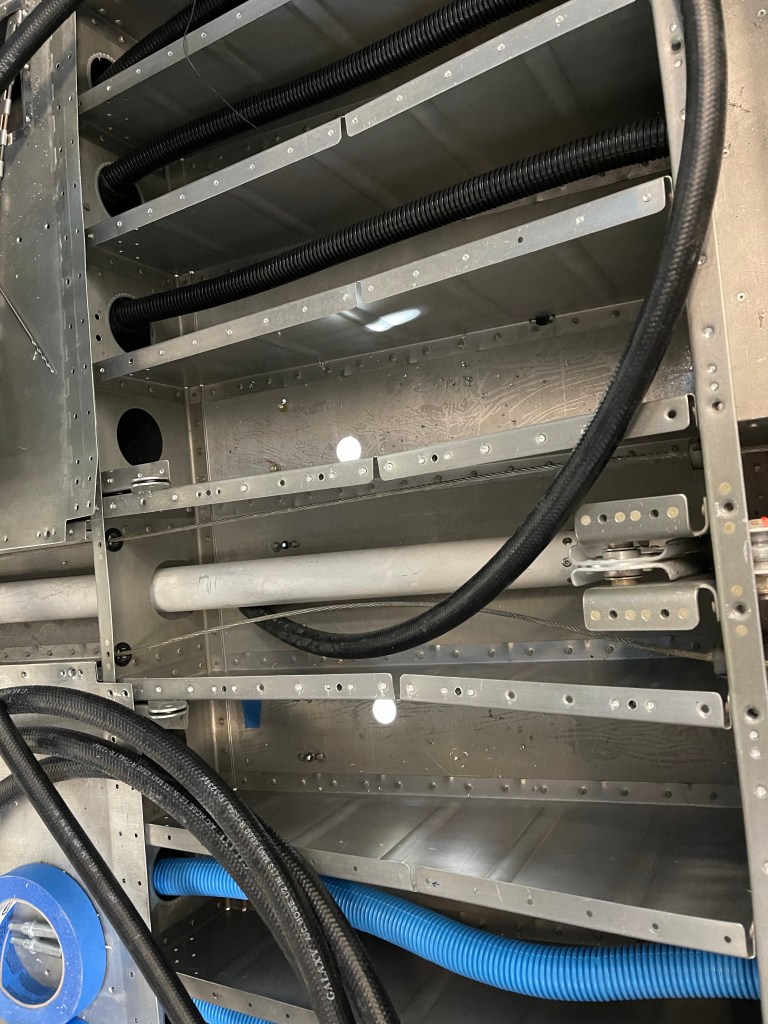
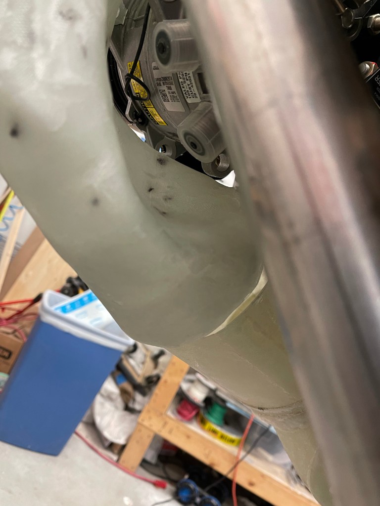
I finished up the routing of the AC hoses down the right side of the fuselage. The hose going all the way to the tailcone dives down towards the floor and goes through the bottom most lightning hole to make sure it doesn’t interfere with the flap tube in the next bay aft. I placed a small piece of angle on the angle attached to the side skin, used nut plates to screw the 2 angles together and then utilized a nut plate to keep the hose from rubbing on the angle attached to the skin.
View of the metal piece riveted in all 4 corners of the lowest lighting hole with a bushing through the center for the hose to pass through.
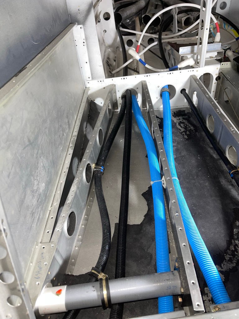
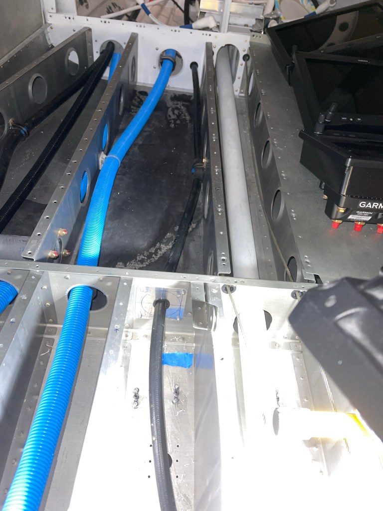
The hose destined for the condenser scoop, goes across the flap tube area on it’s way across the tunnel and to the 1st bay under the left-most rear seat.
Hose continuing to the tailcone under the right rear seat.
I utilized Adel clamps anchored to the step to route the hose inward and keep it away from the bolt holding the step in place. It then makes its way aft to the tailcone.
Similar for the hose going from the condenser to the tailcone.
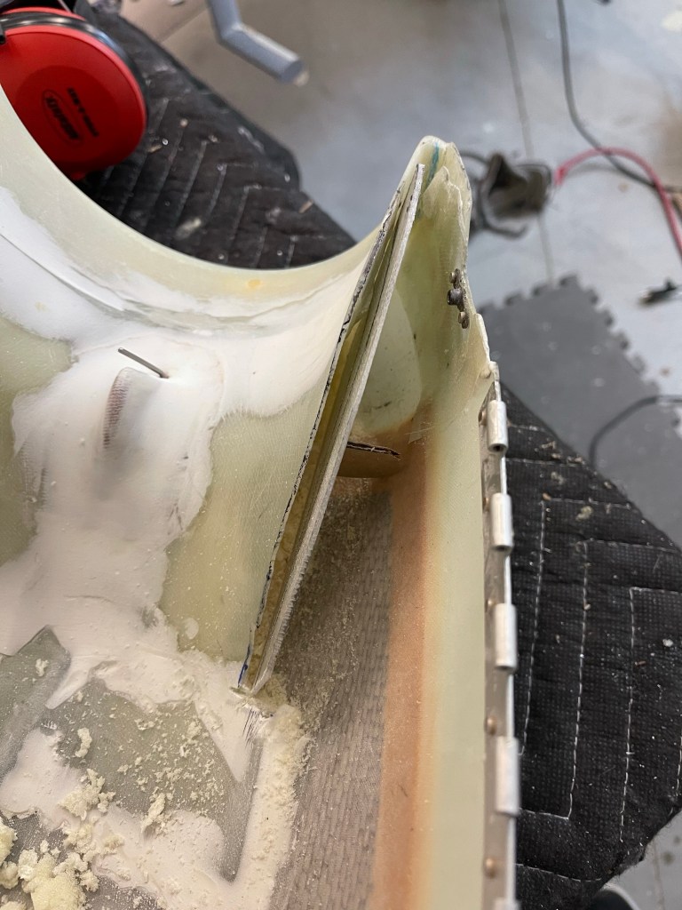
With the hoses done short of crimping on the ends, I started working on the evaporator shelf by using cardboard as a template.
I test fit the cardboard until it was trimmed correctly to sit between the longerons.
I then used the cardboard to mark up the fiberglass shelf and trimmed it, sanding a little bit to get a good fit. Shown here as well are the 3 holes matched drilled into the shelf brackets that get riveted to the longerons.
One other small task was to trim the upper cowl ramps and add a “wall” so that the baffle material could sit in-between the upper air ramp and this “wall” so it has something to push against.
Using some scrap fiberglass to trim up a “wall”
I then mixed up some flox and bonded the “wall” in place with a small “D” shaped piece to provide support against the cowl wall. This was repeated for the other side.
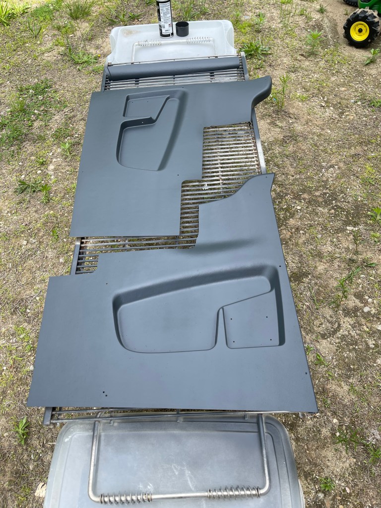
One nice day, I decided to head outside and paint the interior panels. I ordered the lighter tan ones knowing that I was going to paint them a darker color. I think they came out nice!
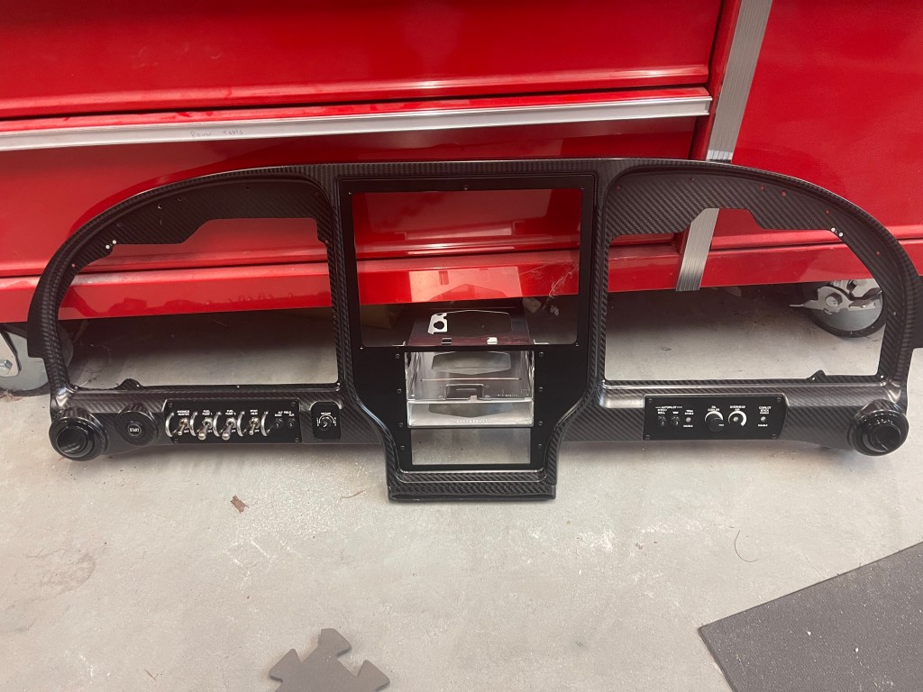
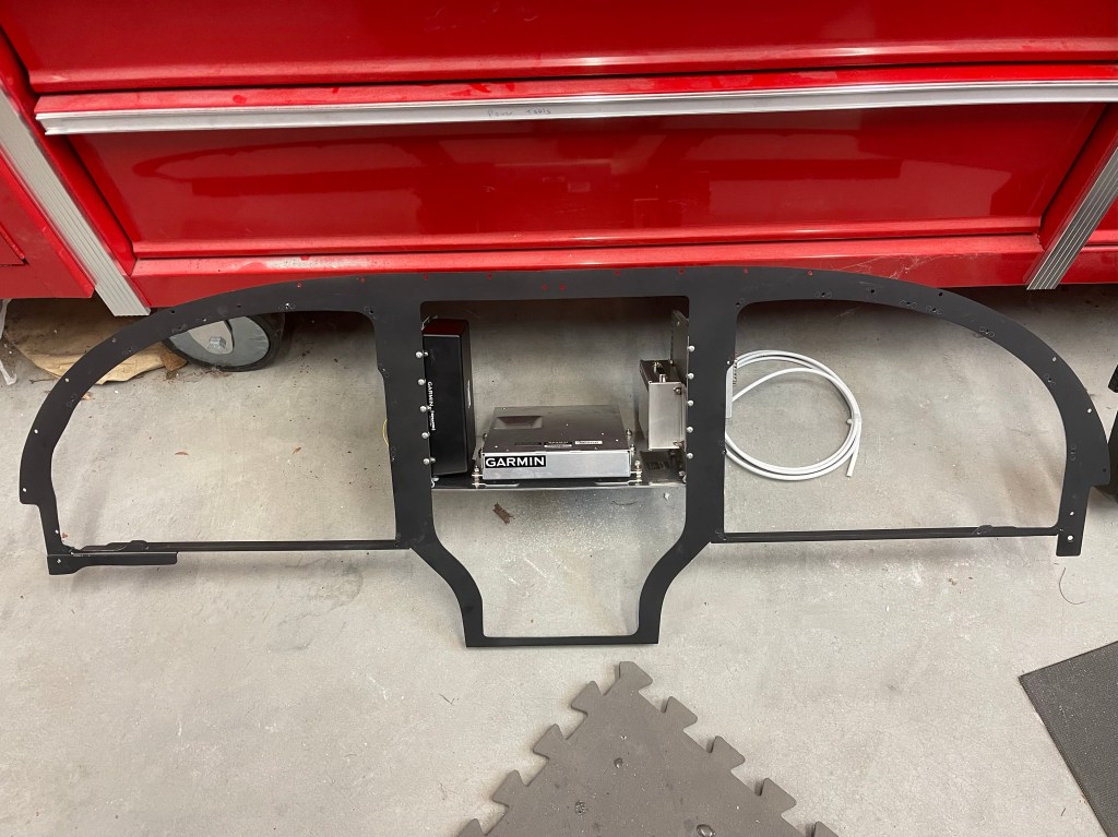
I ran into a snag with continuing with the evaporator install so I worked on completing disassembling the panel. I removed the wiring harness and separated the metal sub frame of the panel from the carbon fiber.
Wiring Harness removedCarbon fiber panelwith avionics trays. Metal subframe with shelf for various components.
I spent some time getting the metal subframe in place, followed by the carbon fiber panel with the avionics trays. This first test fit was mostly done to mark the sub panel where I’ll need to cut away and reinforce making room for the connectors on the back of the 650 etc.. Not a whole lot needs to be removed just a small rectangle near the bottom and really just for the connectors and so the wiring harness doesn’t get bent too much.
I’m probably being a little paranoid here, but I’ve decided to protect the wires coming out of the hall sensors up near the flywheel. These connections are needed to keep the engine running. I fear an alternator belt snapping and whipping around as it’s sort of hung up in the area for awhile cutting the wires. Of course, it would have to cut both wires for it to be a real issue, thus maybe I shouldn’t worry about this too much.. However, the solution really didn’t take too much time to implement. I bent up some 0.032″ metal to wrap around the sensor as shown below. One side has a narrower flange to accommodate the alternator tensioning arm.
Metal cageTest fit.
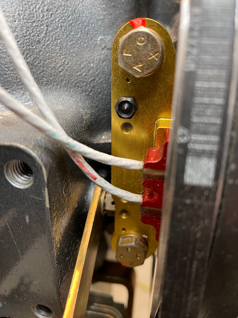
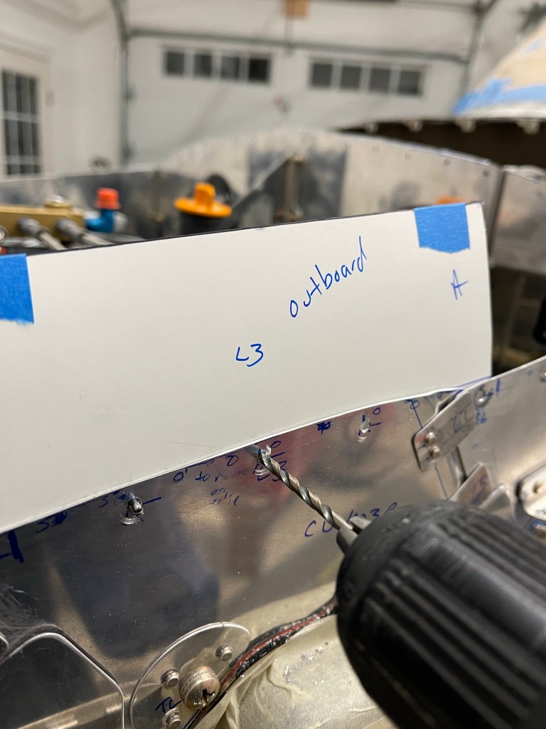
Below you can see the hall sensor and the use of these small center locating punches that screw into a hole and mark the exact location to drill for the bolt.
Punch screwed into position.
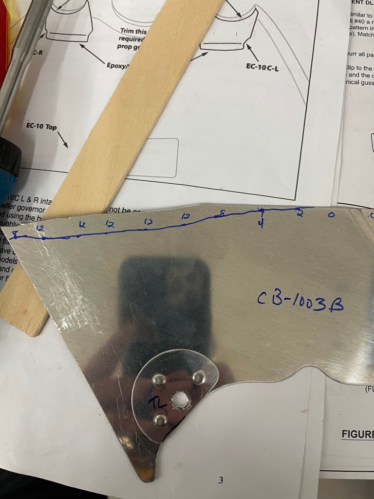
Previously I had used this technique to locate the 2 holes for the SDS fuel pressure regulator on the firewall and forgot to write about it previously. I used a piece of scrap metal to drill and use as a template to drill the firewall.
Punches in place
I placed the unit down on the scrap metal and tapped it with a rubber mallet to mark the location location of the holes that needed to be drilled.
You can see the punch marks on the scrap metal ready to drill.
This technique worked perfectly and allowed me to drill holes for the regulator on the firewall that exactly matched the hole location on the regulator.
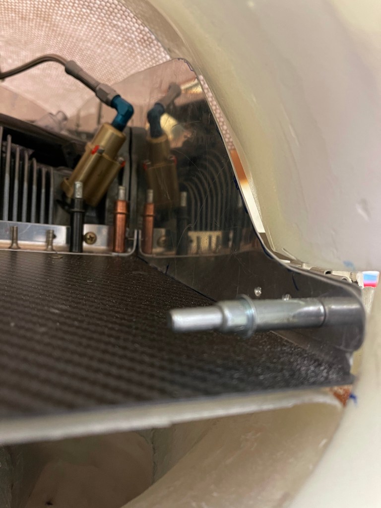
Back to the metal guard for the hall sensor… I punched the top side, drilled the hole, and once that hole was located, I installed the bolt and marked the location of the 2nd hole then drilled that and bolted it to the hall sensor mount. Below is a test fit of both bolts installed.
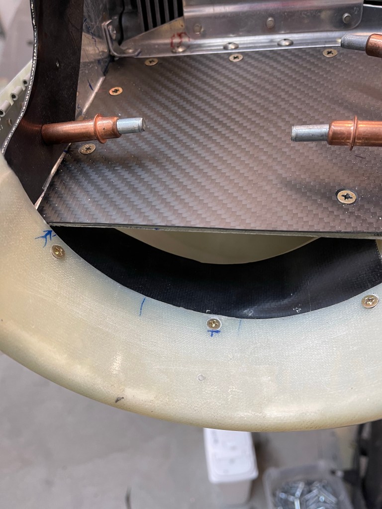
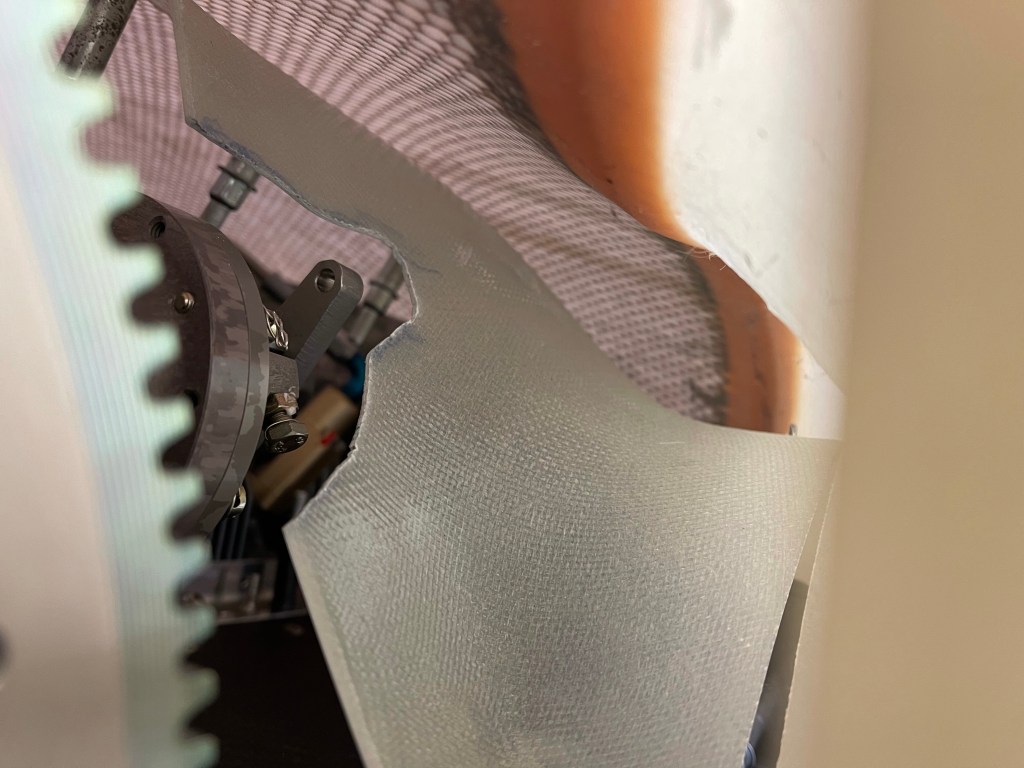
I re-used some aluminum fuel line to route the wires from the hall sensors through. I used an Adel clamp to secure it with the one of the bolts. drilled a hole through the baffle and installed a piece of angle on the aft part of the baffle for another adel clamp.
Front part of the tubing with adel clamp. Aft part of the baffle with angle and adel clamp.
Below is the whole thing put together. Obviously the wires will ultimately be routed through the tube, but I need to remove the baffle and paint it at some point, so waiting to do that until after that is completed.
Also the DB-9 connectors on the end of the hall sensor wires are soldered on.. so another reason to delay putting them through the tube just yet.
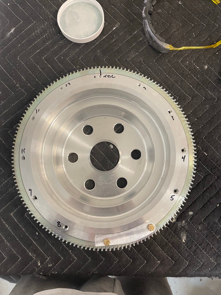
My engine builder supplied a flywheel with the magnets for the SDS system already installed, but I needed to install the magnets in the dual pulley flywheel suppled by Airflow AC. I basically followed this blog linked on the SDS website. https://tasrv10.com/?p=2822.
Below is drilling the holes with the drill guide provided by Ross.
I wasn’t quite as lucky as the linked blog post and the hole sort of ate into part of the grove, but not completely.
Drill hole location.
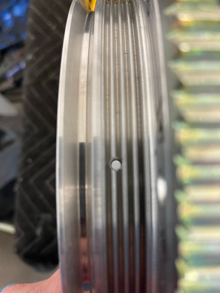
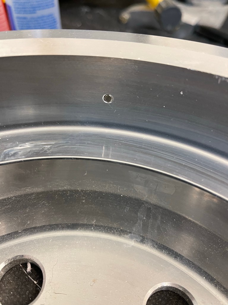
I mixed up some 5 minute epoxy, as specified, and also applied red loctite onto one of the grub screws, which was inserted into the hole from the outside. The magnet was inserted into the hole from the outside. The grub screw was screwed down until the magnet was basically flush with the inner surface of the flywheel.
Magnet flush with the inside
Once everything cured.. I decided to buy the Devcon Titanium putty recommended in the in the linked blog. It is expensive and you really need a very small amount compared to what is provided, but I didn’t want to skimp on this. I prepped the flywheel and applied the putty to each hole location as shown below.
Putty applied to one of the holes.
I let the putty cure for approx. 3 hours and then sanded it using a combo of files and sandpaper. It was a bunch of work, but the end result is what is shown below.
End result of the putty sanding
One other thing left was to size up the air intake into the left size heat muff. I mocked this up with some skeet tubing I has lying around. It seemed like it would work, stealing some air from the left side intake,.
I cut a 2″ hole in the left snorkel.
2″ Hole cut
I took a 2″ duct and flox’ed it in place over the hole that was drilled. Once cured, I re-test fit the skeet tube to the exhaust.
Test fit of the heat tube.
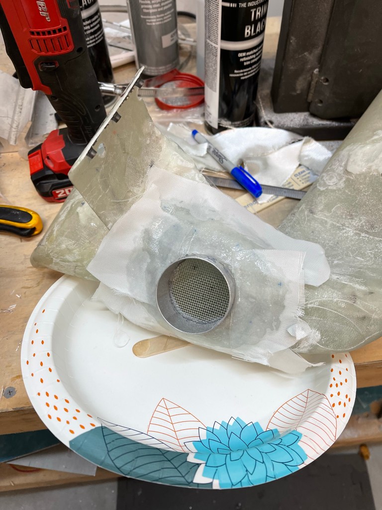
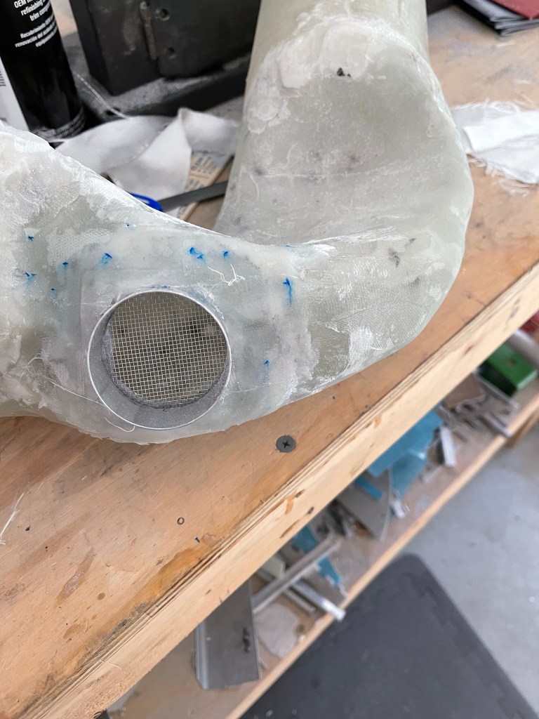
I then laid up some fiberglass cloth and some peel ply to glass over the flanges of the 2″ metal tube.
FiberglassCoth and peel ply curing. Finished product.
I was then able to get back to finishing up the condenser install of the Air conditioning. I utilized some scrap metal along with some construction paper to mark out the center lines of the connections on the aft side of the unit. I did decide to use some straight connectors that Airflow systems provided to put the connections in the first bay from the tunnel.
Marking the center lines of the aft connections.
I used some cardboard to enlarge the holes and make sure the holes were in the right position prior to drilling into the bottom fuselage. Everything seemed to be correct.
Cardboard template
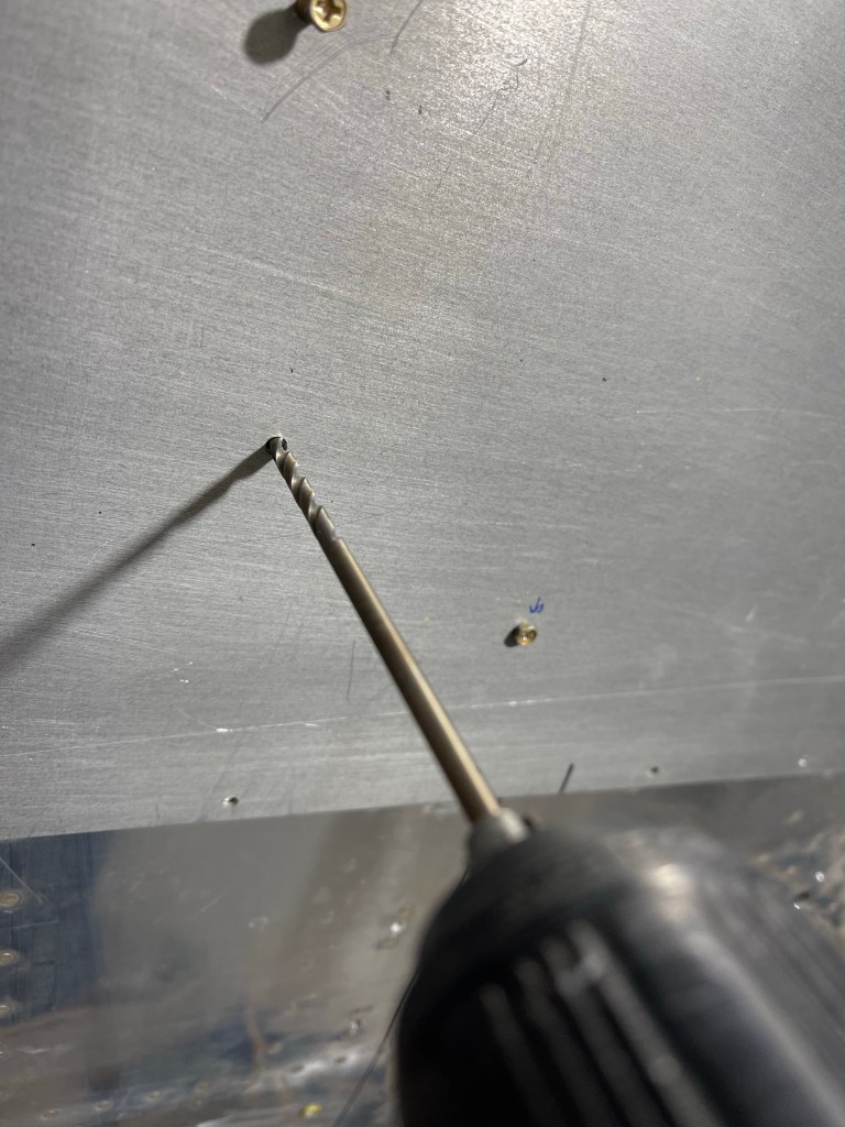
I then took the metal template and screwed it into position and prepared to drill the holes to mark out where the hoses are to be placed.
Metal template in position. Drilling the hole .Both holes drilled to final size.
Then I screwed the AC scoop into position and test fit the aft hoses that go up into the fuselage. Everything worked out well as shown below.
Holes drilled and connections inside in place.
I installed some grommets into the holes to seal them as much as possible.
Grommets in place
A view from the inside with the connections coming up through the fuselage skins.
In prep for installing the baffle material, I used my go-to method of using construction paper to make templates for each piece prior to cutting the actual material. I targeted 2.5″ above the metal baffle material based on what others have done. I did a few test fits with the upper cowling on to make sure that length seemed like it would work. I tied to make the pieces overlap around the split points in the metal in case I ever need to take the whole assembly apart at a later time.
Tempates for baffle materialWorking my way around the engine. Another viewAll done with templates.
I then marked the templates with a line along the metal baffles to mark their position for reinstallation later on. I also marked out a line with enough edge distance for drilling 1/8″ holes to pop rivet the baffling material to later.
Once that was done, I removed the templates and cut out the material one piece at a time. I tried to cut such that the natural curve from the material roll would be in the direction I wanted the material to lay.
Cutting the first piece. Test fitting it in placeInboard viewFirst couple of pieces done.
The method I found worked the best to punch holes in the baffle material was to first tape the template on the piece.
template taped in place
I then used the previously drawn line to place the template/piece assembly in place relative to the metal baffle making sure I had enough material for the overlap spots to the adjacent piece. I would use a drill to cut away the construction paper enough to mark the spot of the hole to be punched. I did the first 2 holes, then punched holes.. put the piece back into place with clecos and then drilled the remainder of the holes so I didn’t have to try to hold the assembly in position for the entire sequence.
Drilling away the construction paper at the hole locationAll holes marked with the drill.
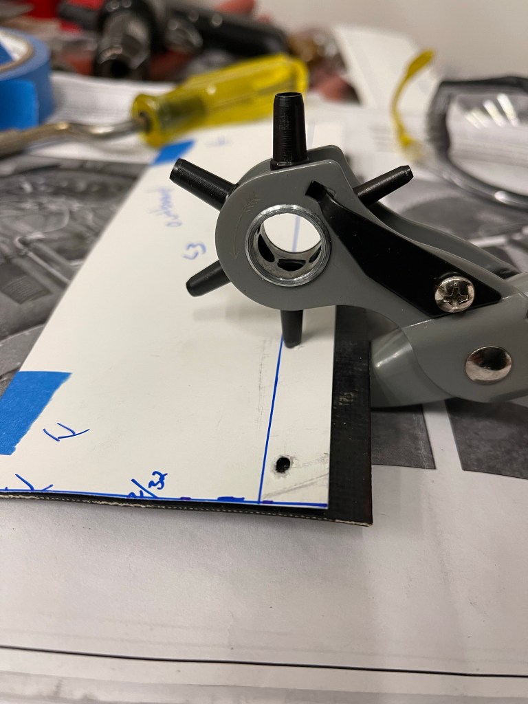
I then used a punch to make the hole in the proper spot in the silicone baffle material.
Punching the holes in the baffle material at the proper locations.
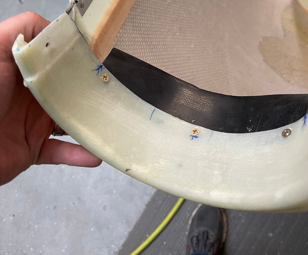
Below are some pics of the final install. I did have to take some of the curl out of these pieces as they tended to curl inwards a little too much. I rolled each piece by hand in the opposite direction and sat some weight on the pieces to take some of the curl out. I also used some duct tape to hold adjacent pieces somewhat together. This will simulate the eventual RTV that will be used to hold everything together.
Closeup of Prop Governor area.
I then did something similar to the plans for the stock cowl to bridge the gap between the air intake tubes and the cowl. I used the metal strip material provided and curved it to match the round intake shape of the cowling. I then matched drilled 3 holes for #6 screws to hold this to the cowl. I cut some additional baffle material and used contact cement to adhere to the metal strips.
Metal strips formed to cowl curve with baffle material adhered to it. View of lower cowl with baffle material added.
Below is a picture of the iniital test fit of this strip/baffle material fit. It seals up the small gap between the cowling and the intake tubes by resting on the inside of the air intake tube. I’ll likely trim this piece a little more for a better fit. Note also that I was sort of holding this in position to take a picture so the alignment is a little off, but you get the gist of what I am trying to accomplish here.
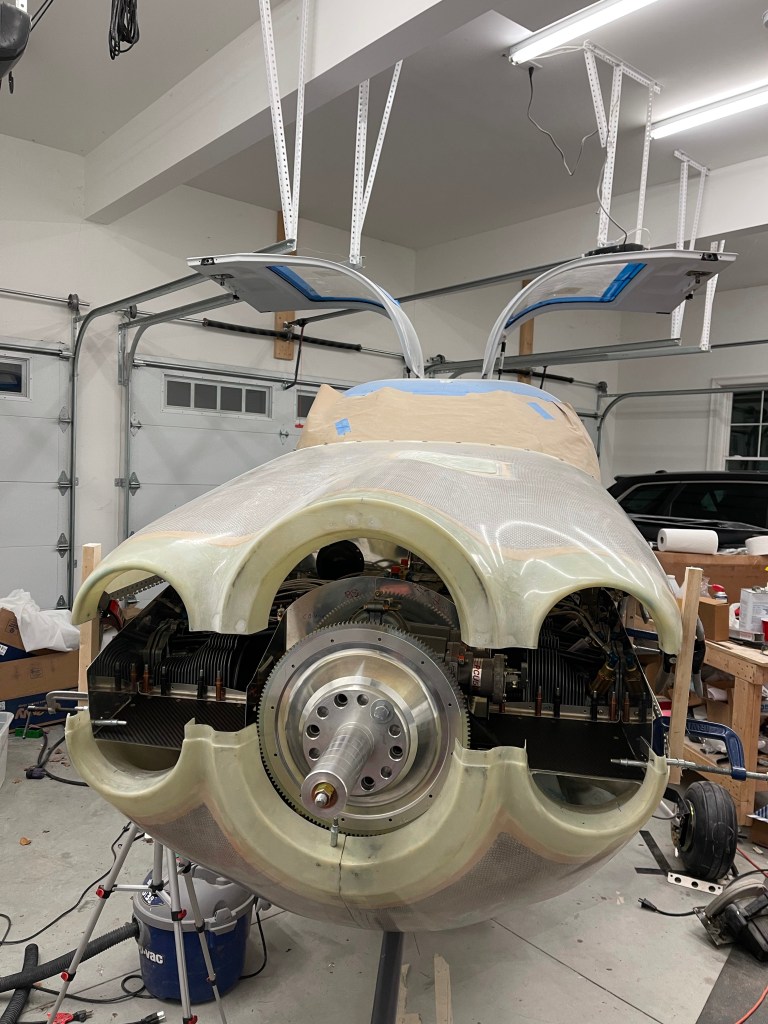
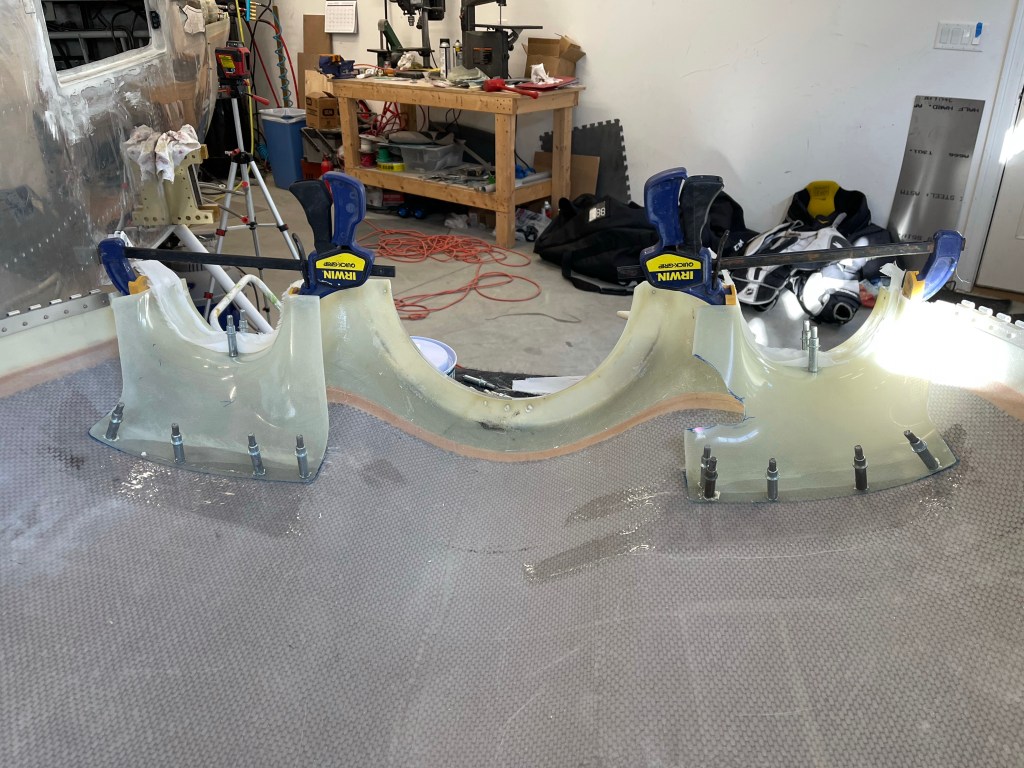
In order to get the top cowling back on, the baffle needed to be trimmed. I saw two ways to do this, and I ended up sort of using both. I started by elevating the top cowl 6″ above the lower cowl. Care was taken to make sure it was aligned both fore, aft, left, and right to the bottom cowl. I just used some pieces of scrap wood and clamps that I had lying around on each corner on the outside of the cowl. I measured in multiple locations along the horizontal split to be sure I was satisfied before moving on.
Cowl elevated 6″More of a front view.
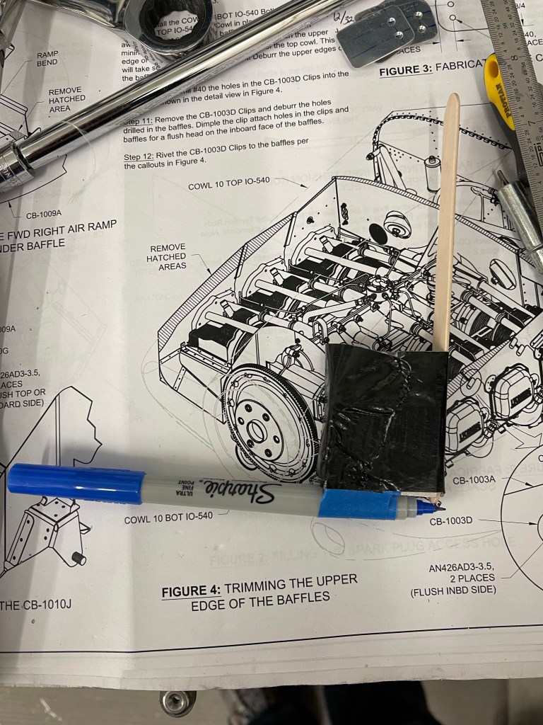
I then made a tool out of a tongue depressor and an aluminum block I had. I taped a sharpie to the bottom of the block and adjusted the stick to get exactly 6″ from pen to top of the stick. I didn’t take any pictures, but the idea here is that you have enough room (with the 6″ elevation) to get your hands/arms inside to hold the stick at a 90 degree angle with the sharpie along the inside of the baffle. Holding the stick on the inside of the upper cowl, you move it aft tracing the contour of the top cowl onto the baffle which will serve as a trim line.
I then trimmed to that line. That basically got me to flush. One could certainly add some extra to the length of the stick to get the the gap you’d like to achieve. Instead, once the initial trim was done, I utilized the 2nd method of paper clips all along the baffles. You barely stick them on and then place the top cowl into position. They slide downward and give you an exact indication of how much gap you have at that location to the top cowl.
Paperclips in position to measure gap
Below you can see the results of the first attempt. You’re shooting for somewhere between 12/32″ and 16/32″ gap per the plans. At each paperclip location, I wrote the number of 32’nds needed to get to 12/32″ by measuring how high each paperclip was above the edge of the baffle.
Measuring current gap
Those measurements basically were used to draw a new trim line.
Marking a more precise trim line.
I ended up doing this for a couple of cycles until I was completely satisfied with the gap all the way around. Making smaller adjustments in specific areas as I went. Below isn’t the best picture, but it was the results of the baffle trimming with a gap to the top cowl.
I fabricated the clips and drilled them into position per the plans. I’m holding off riveting most of this stuff until later.
Now that the baffles were trimmed, I decided it was time to affix the top cowl inlet ramps. I placed them into position with clecos and some scrap metal strip to hold them in place at the front.
I then test fit the cowl and had to trim the outer side baffles more to account for the curvature. I did get somewhat lucky due to my cowl being so far forward based on my prop/spinner setup compared to most. The ramps didn’t require trimming at the prop governor to at least test fit. I did end up trimming around to give some more clearance, which I’ll foam in later to provide a good backing for baffle material.
No initial trimming required for prop governor.
Once I was happy with their location, I epoxied them into place. Later I will layup some cloth, but for now just epoxy to hold them in position. I also did a single layer of cloth and some peel ply on the inlet circle just to hold that area into position.
Epoxy ramps into place. 1 temp layer of tape with peel ply on the outside.
I then laid up 3-4 layers of cloth for the underside of the circular inlet.. Placed that into position and let it cure. I sanded down the outside area and added micro. Once that was cured, I sanded to a smooth finish.
Right inlet ramp micro’edSame on left side. Cutout for prop governor
With the upper ramps completed enough for now, I moved on to customizing the center baffles. I started with the right side, seeing it’s the easier side without compressor interference to deal with. I cut the stock baffle leaving just enough flange to rivet a new piece that would angle toward the inboard side of the inlet. I first made a template from construction paper and got it as close as I could. I transferred to metal and worked on trimming to get a good gap to the upper inlet ramps.
Paper template of right side. Transfer template to metal and test fit.
I then spent some iterations trimming this custom piece to match the curvature of the upper inlet ramp with some gap for baffle material. Below are the results.
Right center baffle gap.
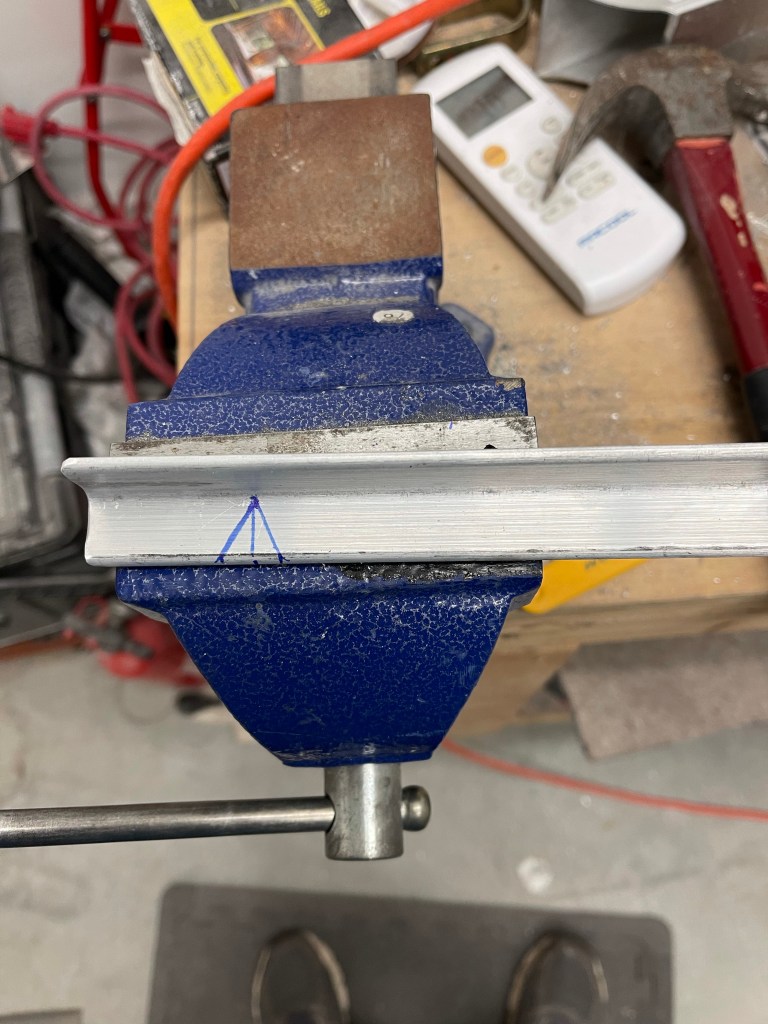
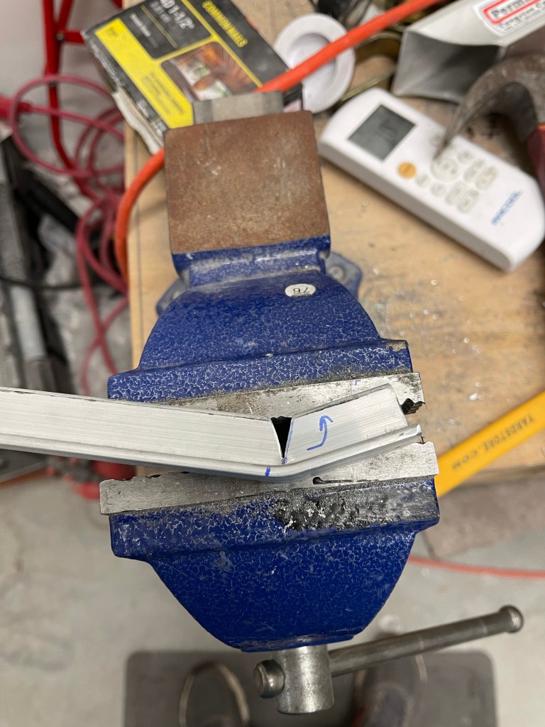
To hold the inboard side in place I fabricated up some 3/4″ x 0.125″ Angle. Seeing there was a slight bend in the baffle I just created near the inlet, I marked a cut to match that bend in the angle. I marked and cut out a “V”
Marking the cut to bend the angleCut made.Bending the angle to match the bend in the baffle.
Below is the end result after match drilling and cleco’ing the baffle to the angle.
I utilized 3 screws to tie the aft piece of metal holding the carbon fiber ramp to the front pieces, including the piece of metal that runs under the carbon fiber ramp. I trimmed the excess away on the inboard side of any carbon fiber and metal plate so it didn’t protrude past the angle.
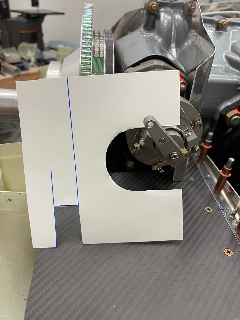
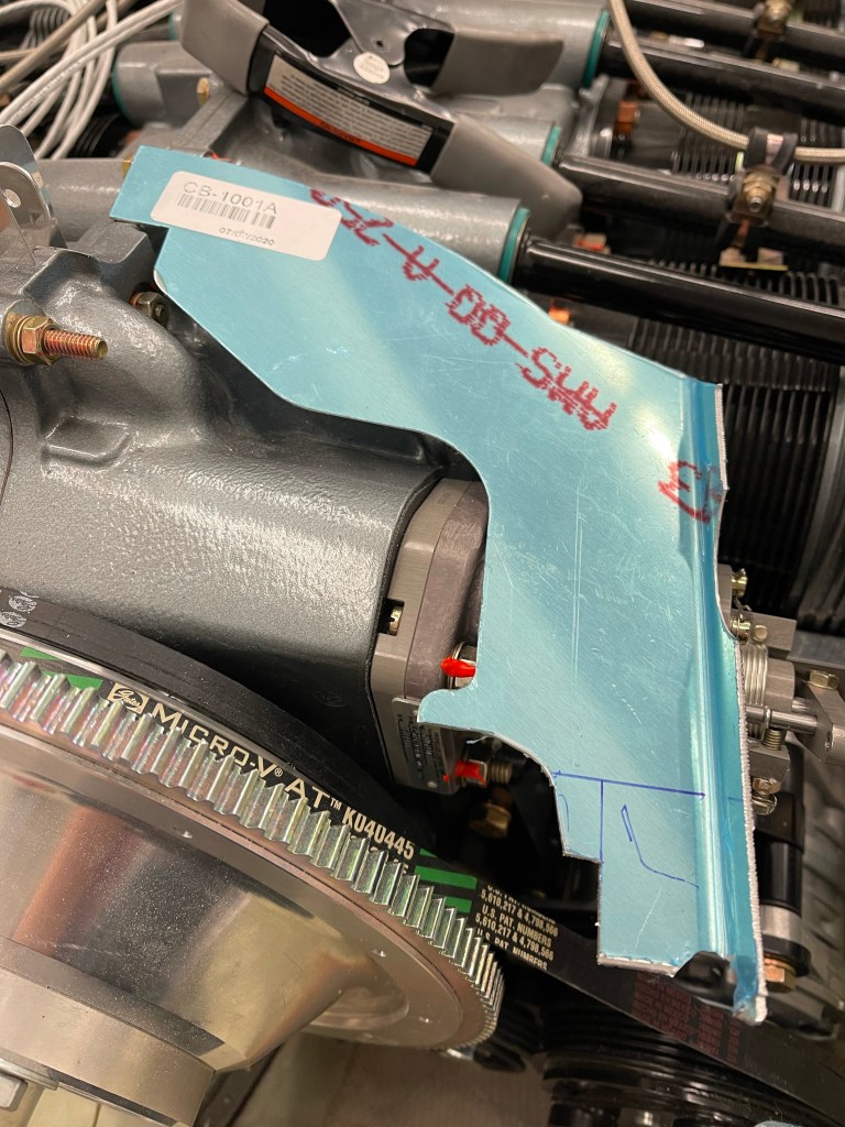
I then did a similar thing using a template on the left side. I decided to use one piece of metal to wrap around the governor and bend around the AC compressor belt to box it out of the inlet area.
Beginnings of a paper template
Once I was satisfied with the paper template, I transferred it onto metal, cut it out, and made the needed bends as shown below.
Initial trim of the custom left baffle. A front view.
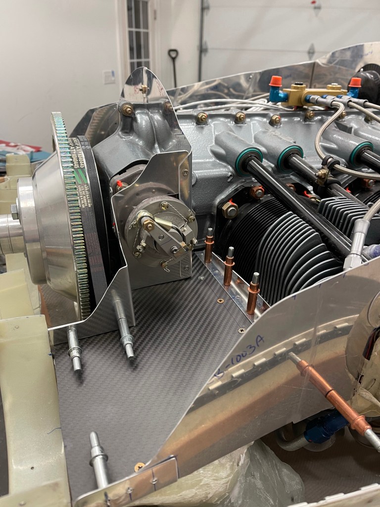
I then worked to fabricate another short piece of angle with a notch cut out for AC belt clearance to hold the inboard side in place. I drilled 2 holes for #6 screws to attach to the stock baffle that I had cut off and left a bit of a flange for connecting my custom piece to.
View of left ramp area with baffles screwed together and cleco’ed to the angleFront view showing the angle and 2 #8 screws holding it in position, allowing clearance for the AC belt. View of the finished up left ramp area. Both ramp areas complete (beside riveting everything). Final picture with top cowling in place.
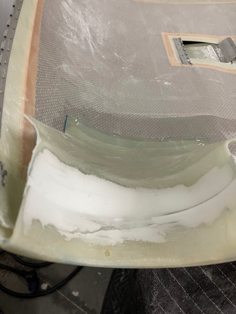
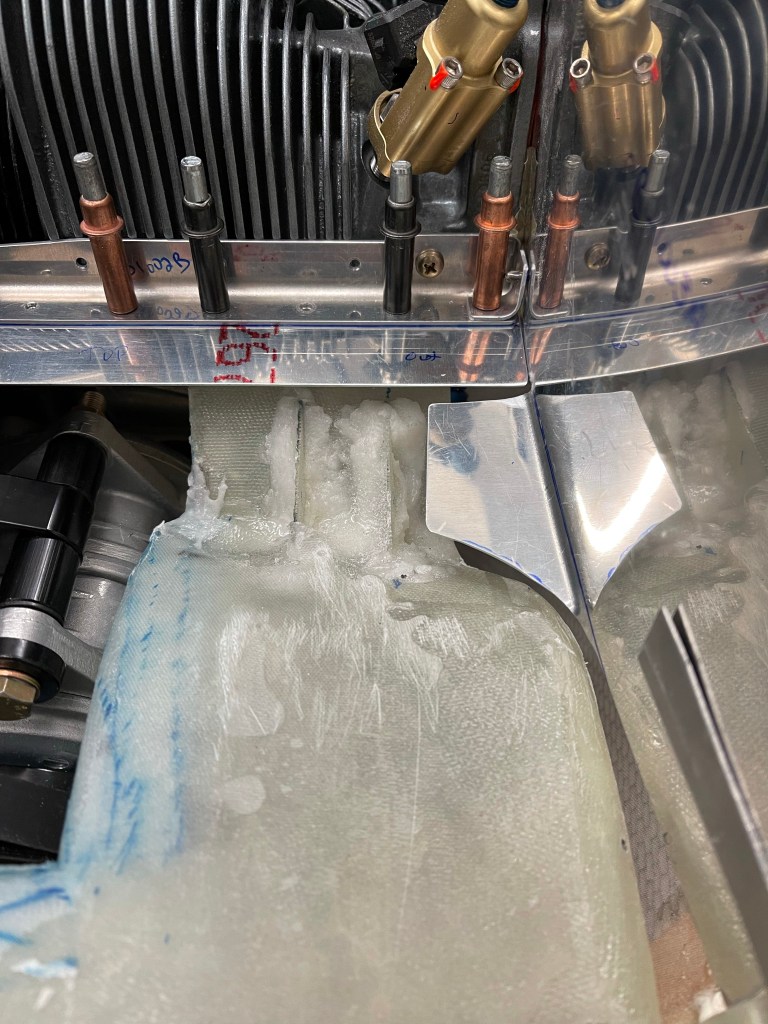
Now that the basic shape of the left intake tube was formed, it was time to sand it down to perfect shape. I used mostly the Permagrit sanding blocks for this task, and it was relatively easy. Of course, at some points I had to put the lower cowl on to make sure I had clearance to it. I also carved out a bit more in the back for the AC hose connections to the compressor.
Foam sanded to shape
I then laid up 4 layers of cloth and put some peel ply over the top and let the tube cure overnight.
Of course prior to doing this I covered the foam in packing tape as a release agent and also sprayed some silicone based release agent on that for good measure.
Once cured, I removed all the foam inside of the tube and test fit it.
I then cut some cloth to close out the top part of the tube where I had cut for clearance to the compressor. 4 layers again were laid up and peel ply placed over the top.
Closing out the top of the tube.
Once cured I test fit the tube once again to make sure things looked good. below you can see the blue sharpie lines that I used to mark the cloth for cutting pieces to shape.
Tube clearance to compressorAft view of bump in for AC hose connectionsCloser look at the bump-in.
Then it was time to wrap a single piece of cloth to span the gap between the two tubes to join them back together. You can see the black line I marked for alignment. I also used a jack to allow the tube to sit on vs. having gravity pull down on the tube while this was curing. I used a single layer on the outside, because clearance to the cowl is a bit tight. Once this cured, I placed a thick layer of flox on the inside of the tube to fill the gap and create more strength in this area.
re-joining the tubes. Complete except for some sanding.
One of the other tasks that needed to be done was to redesign the air ramps seeing I’m using the Showplane’s cowling and the stock metal ramps were cut out for this intake system. I fabricated a .032″ thick piece wide enough to go under the baffle angle and still protrude enough to serve as a flange for the new ramp. This will be bent downward somewhat depending on the angle between this and the from of the intake. It’ll provide a nice flat surface for attaching the ramp material to with screws.
I also bent up some of the side baffle material to provide 1 screw location. I also decided to fabricate up a metal piece that sits up front on top of the intake area. It has a bent flange that will rivet to the side baffle material. I’ve left everything to the inside (closest to the flywheel) long for now. Once I get the center baffles completely figured out this area will be trimmed and I suspect some aluminum angle will be used with some screws to connect the front metal piece to the aft piece I made with screws.
Picture of ramp area prep for screws and carbon fiber ramps.
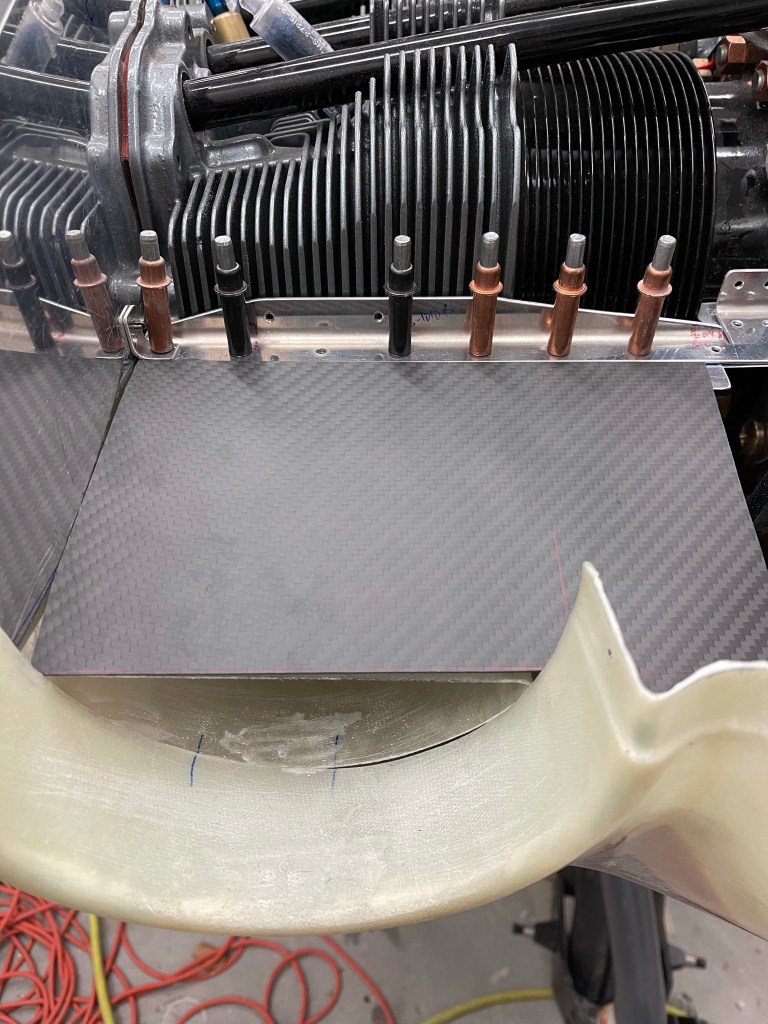
I then cut some carbon fiber material I bought for the ramps to fit in the ramp area. Again, leaving the inboard side long for now.
Test fit right ramp material
I then match drilled everything, added nut plates, and screws to hold everything down.
Right Ramp.
I put the center baffle material in place after cutting it somewhat. This will need to be angled back towards the intake opening. In fact, I may cut the piece coming out towards the flywheel and rivet in a new piece of my own at an angle to achieve this.
RightCenter baffle piece in place
I really had to trim away the left center baffle piece. It interferes with the AC compressor quite a bit. So I decided to cut the forward most section completely off, leaving enough material to rivet more metal to later, and also the notch for the aft part of the prop governor. Later, I’ll work on a custom piece to go over the prop governor and along the ramp to the intake area.
Working on the Left center baffle Match drilling the hole for the 2 center baffles.
The same process was repeated for the left, with the exception that the compressor complicates the ramp..
Metal flange for ramp added
I decided the best way was to use construction paper to create template prior to attempting to cut the carbon fiber piece.
Creating a templateTransferring template to carbon fiber. Ramp cut and in place. Another angleBending up the side baffle for a screw location. Ramp in place!Another view. Looks like a #6 nutplate made it into my #8 bin.. I’ll have to fix that at some point.. All finished up with the left center baffle in place.
Now that the main part of the cowl is fitted, it was time to move onto getting the baffling started.
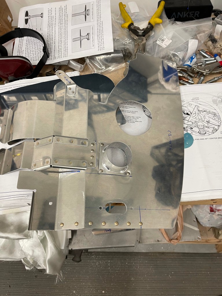
The start of section FF2 of the plans.
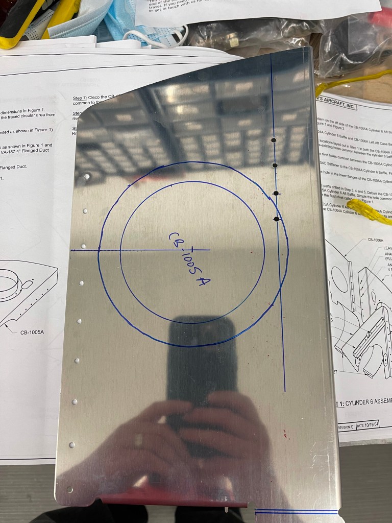
You start off by marking up the #6 cylinder baffle for the scat tube that’ll go to the oil cooler. Also some holes for the top spark plug wires to pass through. Below you see the flange located in place and some holes drilled per plans.
The inner and outer circles were marked. The inner circle was cut out to allow air to flow through to the oil cooler.
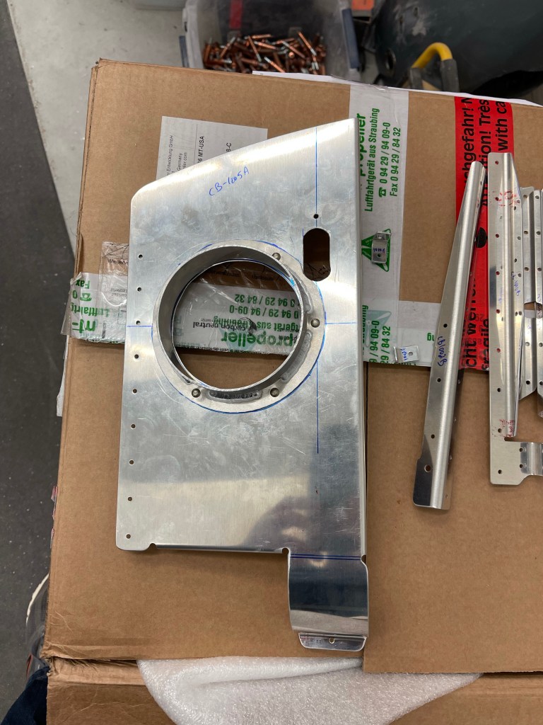
Holes for oil cooler and plug wires cut
The entire #6 assembly is then all riveted together.
A similar thing was done for the #5 baffle. The one thing I did different here was to utilize the RV-14 baffle modification. This provides more space between the aft-most cylinder fins and the baffling to get cooling air through and avoids doing “the washer trick” that several refer to.
It’s key to do this prior to cutting the 2” duct hole as it will need to move up.
I started by cutting off the existing piece of the baffle that wraps around the cylinder.
Cut off baffle piece
I then put the CB-00028, CB-00029, and CB-00030 pieces I ordered from Van’s in place of the wrap around piece that was cut off.
Below you can see that I relocated the 2” duct hole a little higher up on the baffle compared to the plans.
Baffle #5 complete
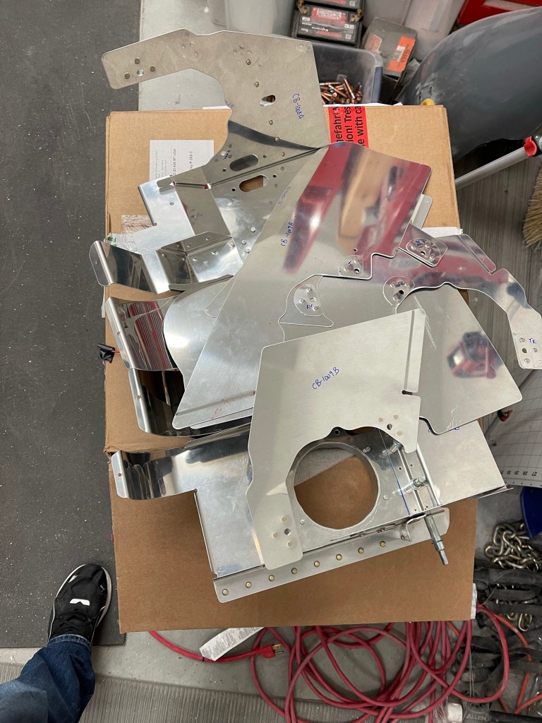
I worked on adding the doublers on the other baffle pieces only to end up with a pile of baffle parts ready to trim, as needed, to fit around my valve covers.
I worked on fitting the #5 and #6 cylinder baffles in place and putting on the Aerosport engine mount covers. 3 #6 screws were used with nut plates to attach making sure to not drill into the mounting ears.
Below the baffling is complete, yet to be trimmed.
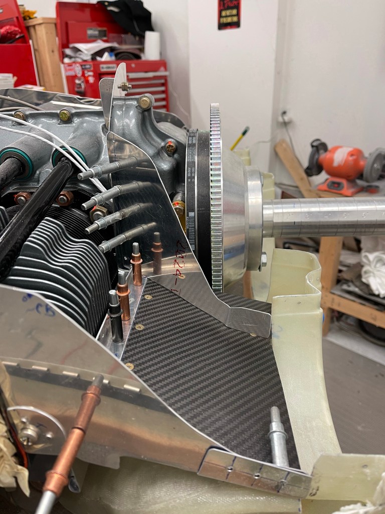
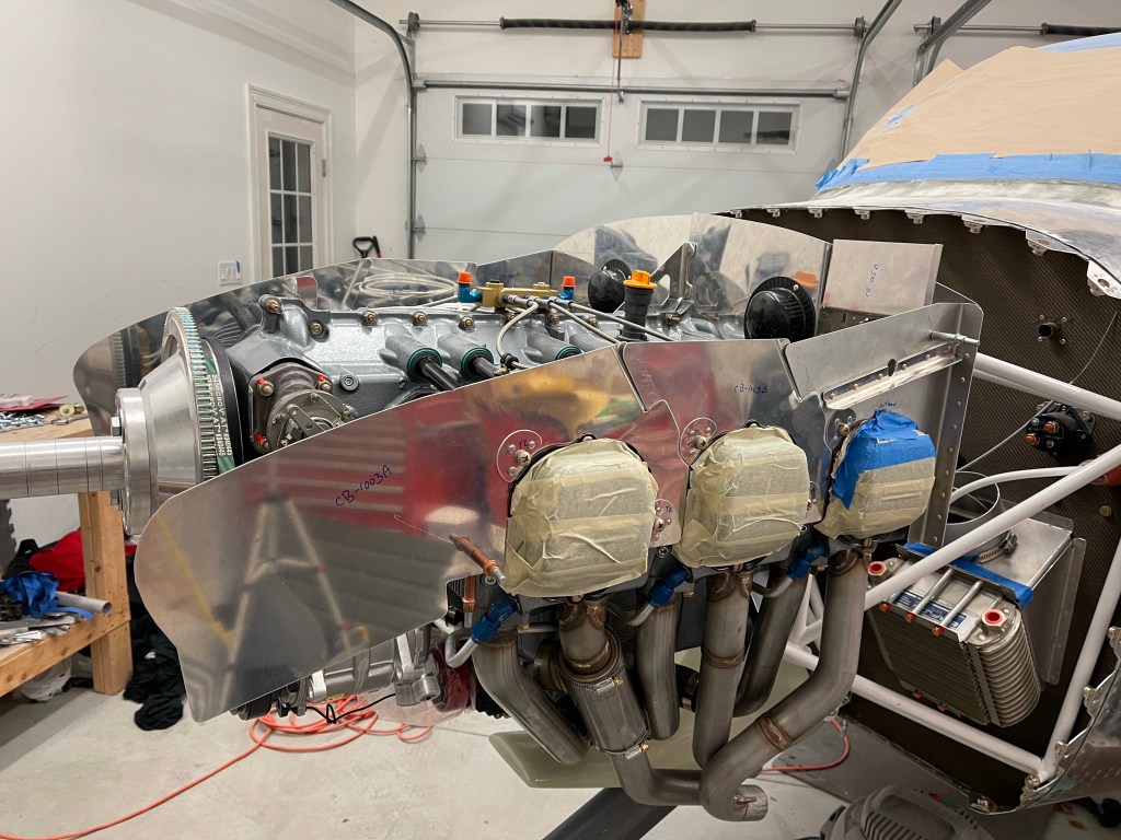
In anticipation of starting on the Showplanes intake I temporarily installed the exhaust pipes.
Right side exhaust pipes in placeLeft side pipes
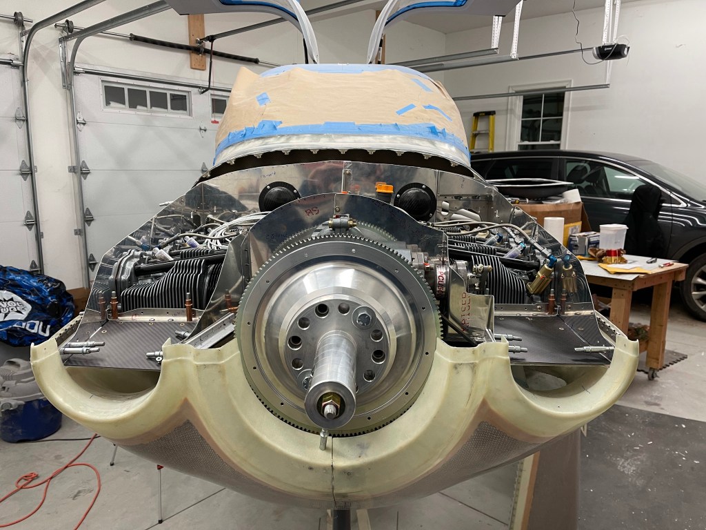
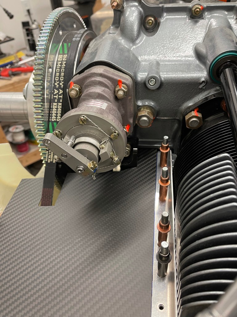
I also worked on making sure my AC compressor was as close to final position as possible. It’s a bunch of tweaking with a couple of different belt lengths, mounting spacers, and arm lengths, to get it all right. There is very little space between the belt tensioner and the starter.
AC compressor and prop governor in place Minimal spacing between tensioner and starter.