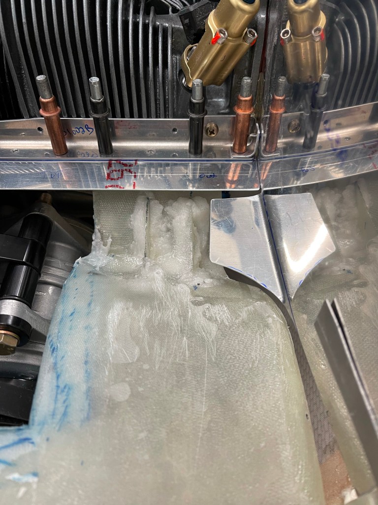
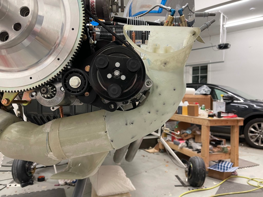
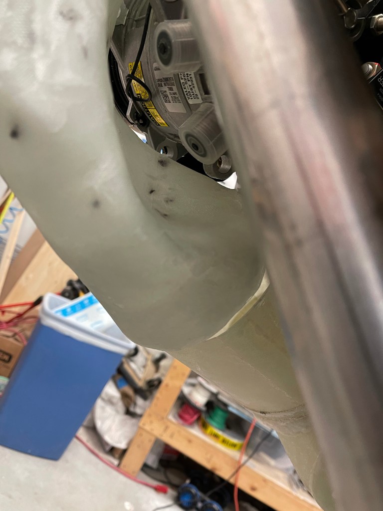
Now that the basic shape of the left intake tube was formed, it was time to sand it down to perfect shape. I used mostly the Permagrit sanding blocks for this task, and it was relatively easy. Of course, at some points I had to put the lower cowl on to make sure I had clearance to it. I also carved out a bit more in the back for the AC hose connections to the compressor.

I then laid up 4 layers of cloth and put some peel ply over the top and let the tube cure overnight.
Of course prior to doing this I covered the foam in packing tape as a release agent and also sprayed some silicone based release agent on that for good measure.

Once cured, I removed all the foam inside of the tube and test fit it.
I then cut some cloth to close out the top part of the tube where I had cut for clearance to the compressor. 4 layers again were laid up and peel ply placed over the top.

Once cured I test fit the tube once again to make sure things looked good. below you can see the blue sharpie lines that I used to mark the cloth for cutting pieces to shape.


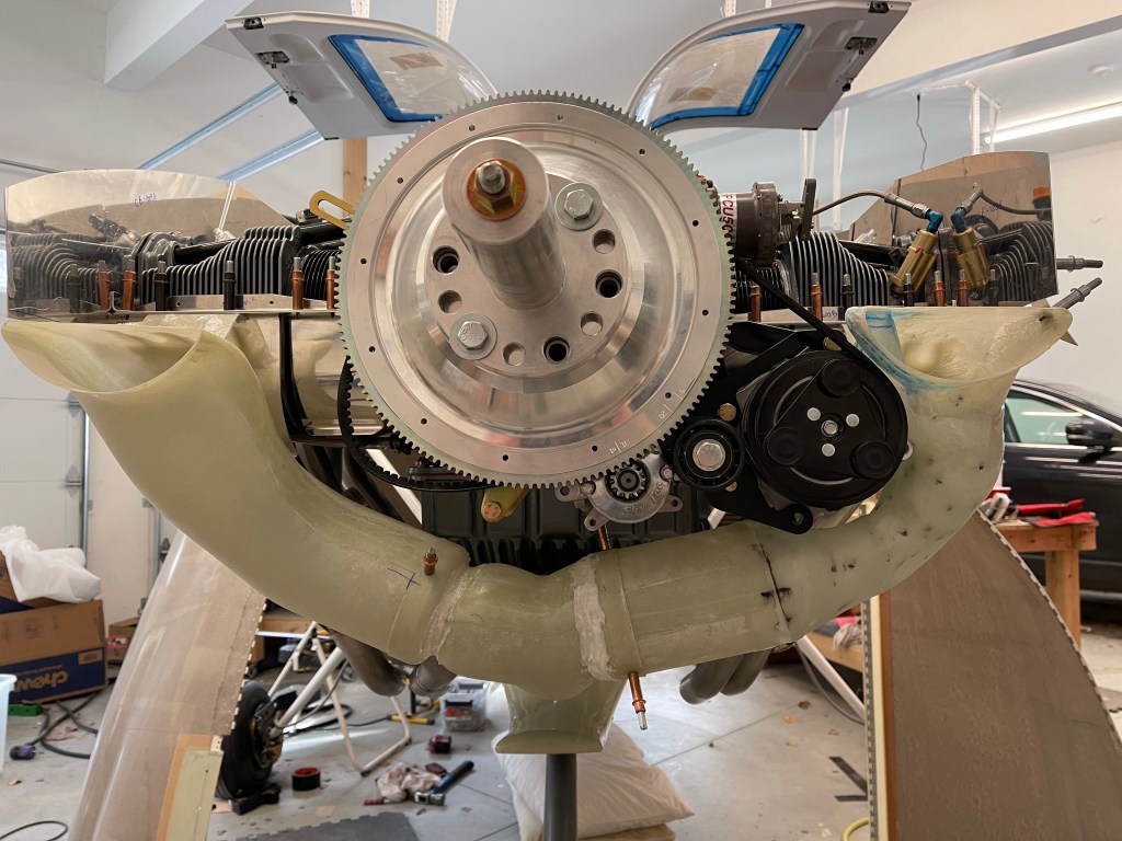
Then it was time to wrap a single piece of cloth to span the gap between the two tubes to join them back together. You can see the black line I marked for alignment. I also used a jack to allow the tube to sit on vs. having gravity pull down on the tube while this was curing. I used a single layer on the outside, because clearance to the cowl is a bit tight. Once this cured, I placed a thick layer of flox on the inside of the tube to fill the gap and create more strength in this area.

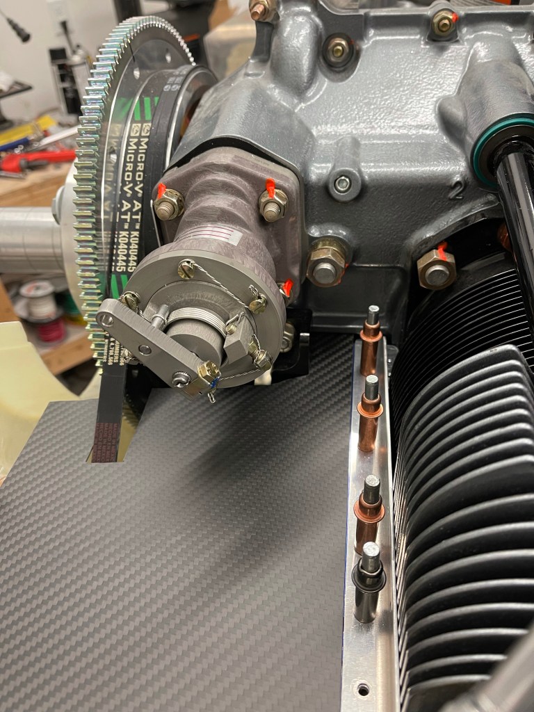
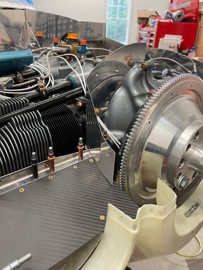
One of the other tasks that needed to be done was to redesign the air ramps seeing I’m using the Showplane’s cowling and the stock metal ramps were cut out for this intake system. I fabricated a .032″ thick piece wide enough to go under the baffle angle and still protrude enough to serve as a flange for the new ramp. This will be bent downward somewhat depending on the angle between this and the from of the intake. It’ll provide a nice flat surface for attaching the ramp material to with screws.
I also bent up some of the side baffle material to provide 1 screw location. I also decided to fabricate up a metal piece that sits up front on top of the intake area. It has a bent flange that will rivet to the side baffle material. I’ve left everything to the inside (closest to the flywheel) long for now. Once I get the center baffles completely figured out this area will be trimmed and I suspect some aluminum angle will be used with some screws to connect the front metal piece to the aft piece I made with screws.

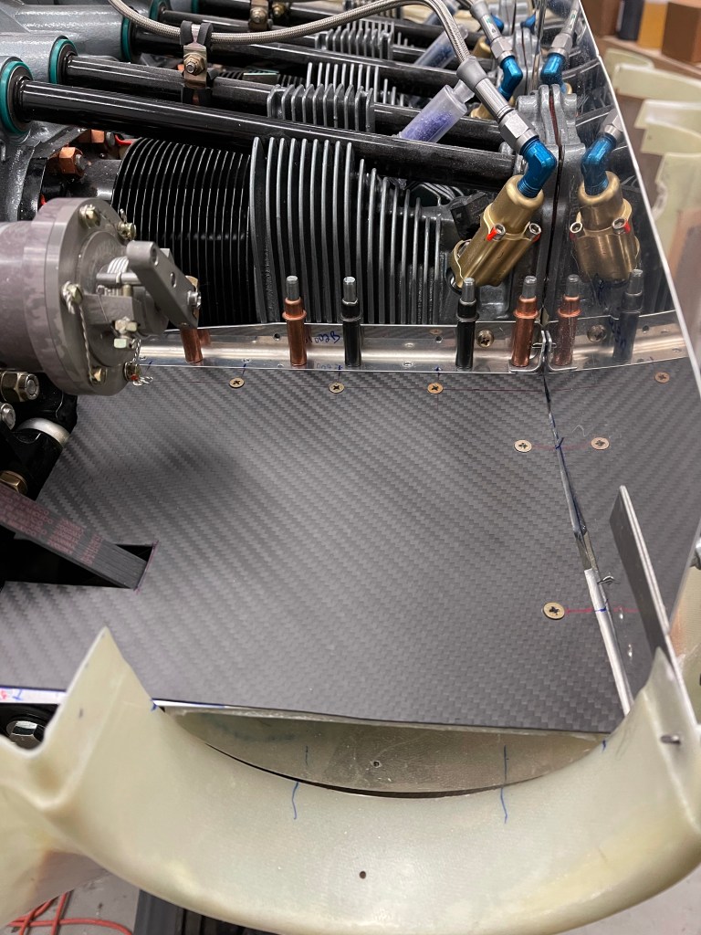
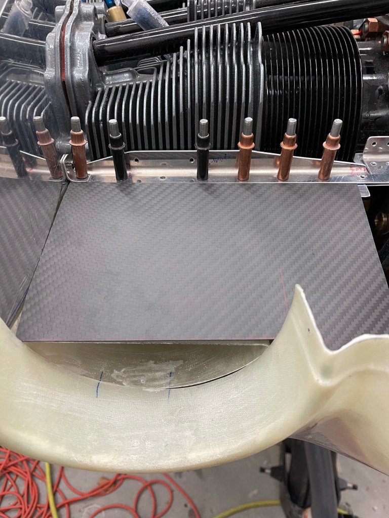
I then cut some carbon fiber material I bought for the ramps to fit in the ramp area. Again, leaving the inboard side long for now.
I then match drilled everything, added nut plates, and screws to hold everything down.

I put the center baffle material in place after cutting it somewhat. This will need to be angled back towards the intake opening. In fact, I may cut the piece coming out towards the flywheel and rivet in a new piece of my own at an angle to achieve this.
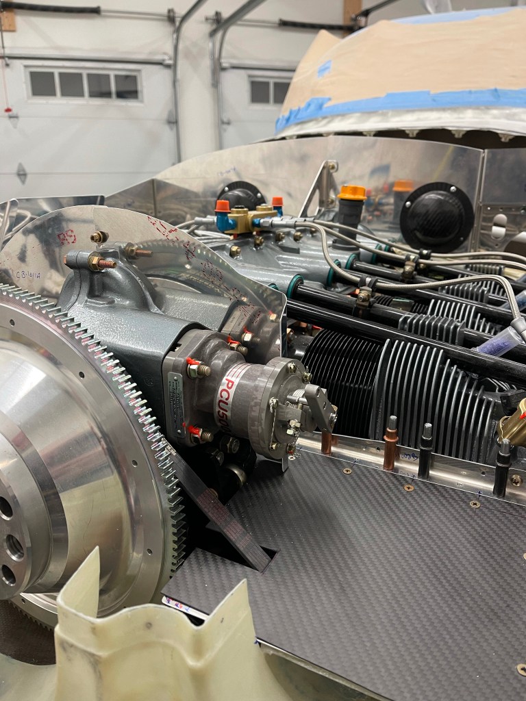
I really had to trim away the left center baffle piece. It interferes with the AC compressor quite a bit. So I decided to cut the forward most section completely off, leaving enough material to rivet more metal to later, and also the notch for the aft part of the prop governor. Later, I’ll work on a custom piece to go over the prop governor and along the ramp to the intake area.
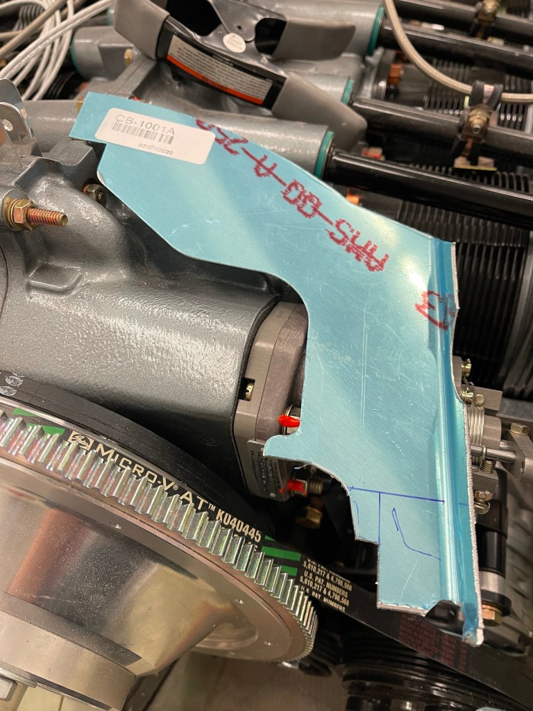

The same process was repeated for the left, with the exception that the compressor complicates the ramp..

I decided the best way was to use construction paper to create template prior to attempting to cut the carbon fiber piece.