Nose wheel and leg fairing

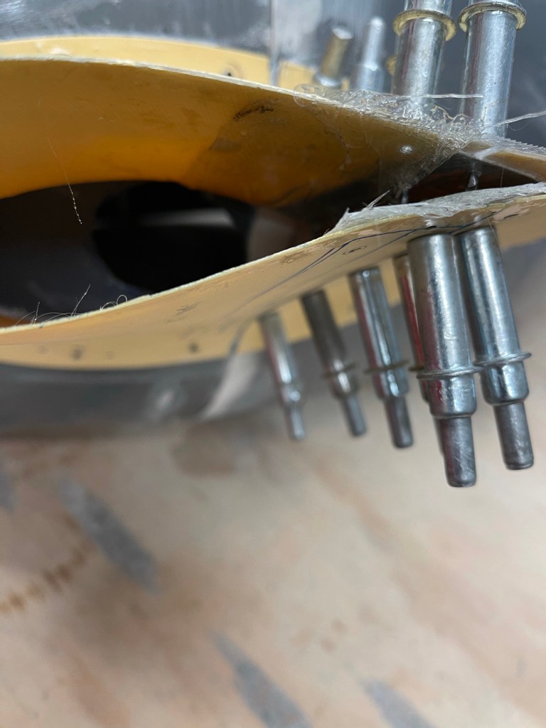
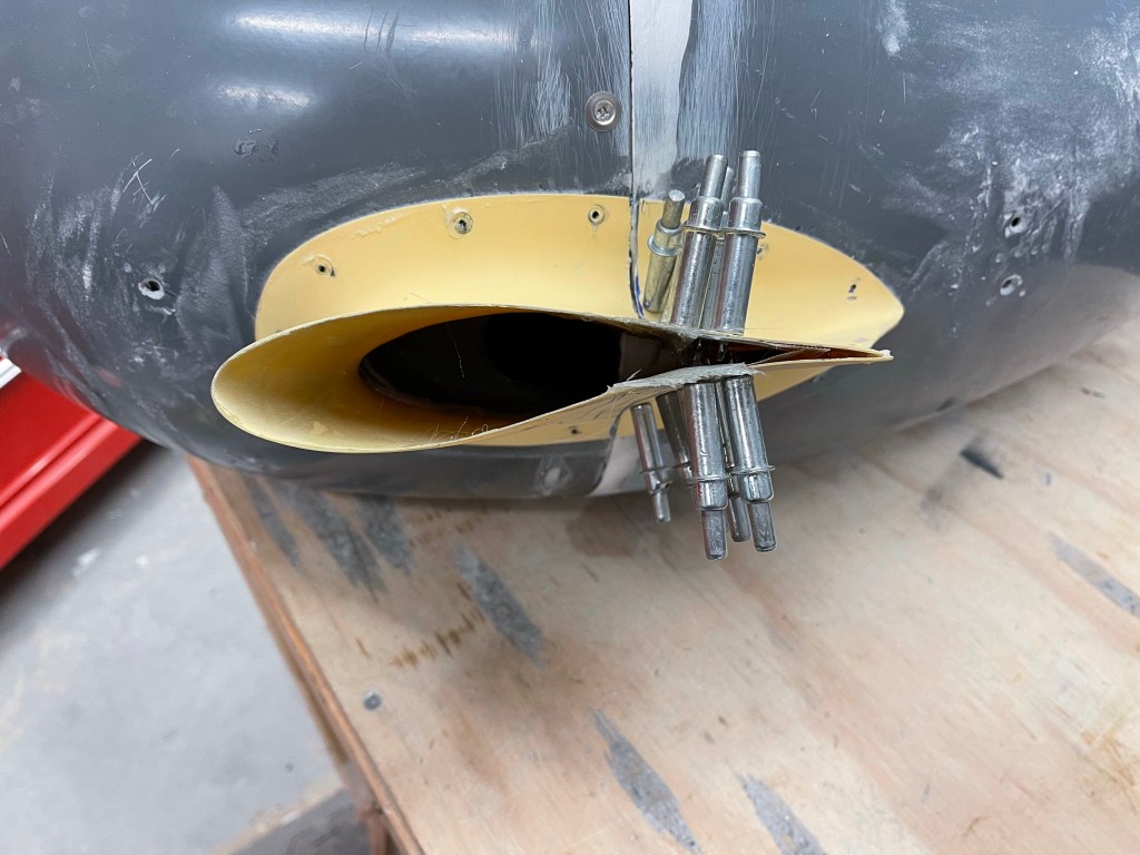
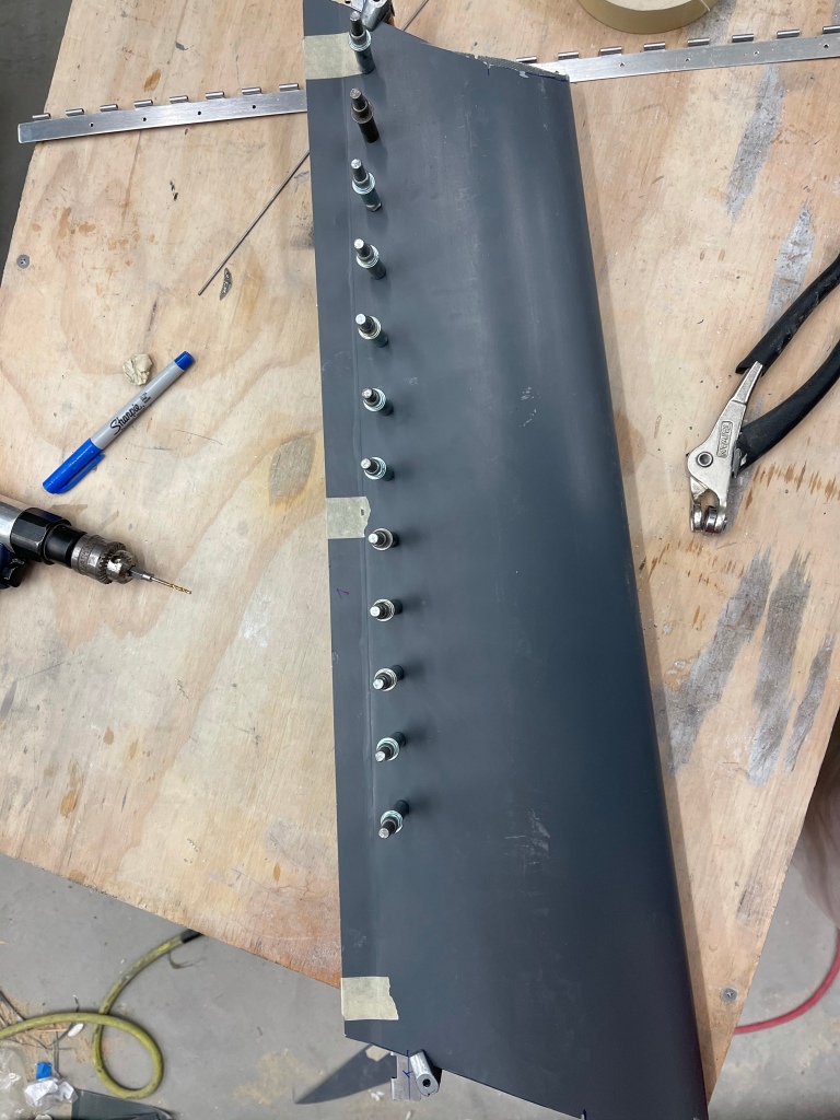
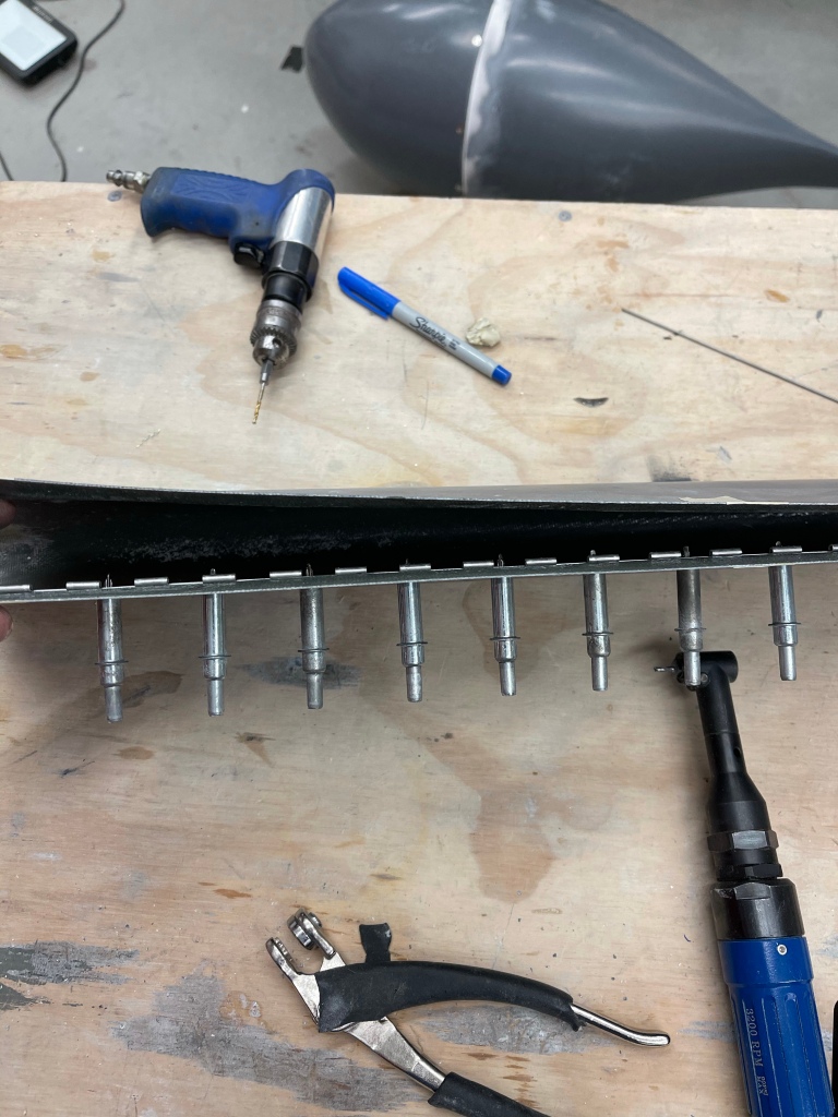
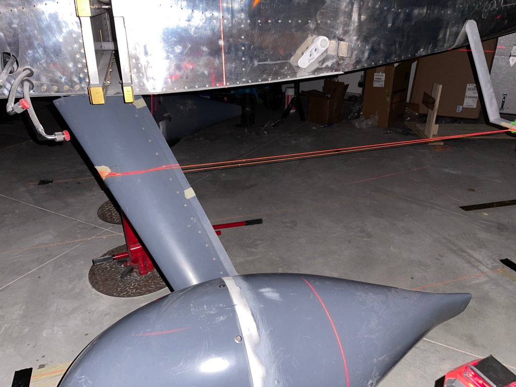
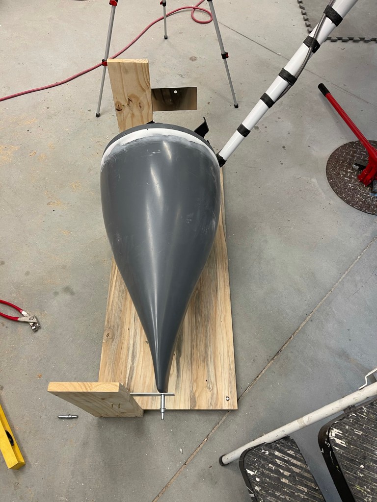
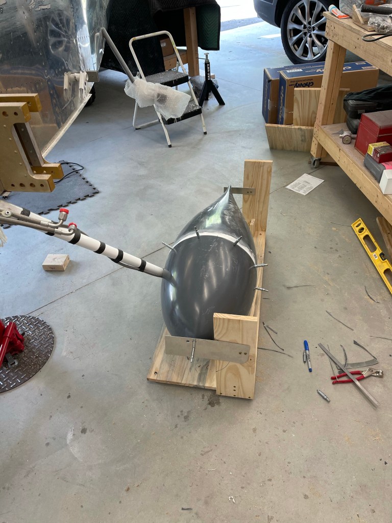
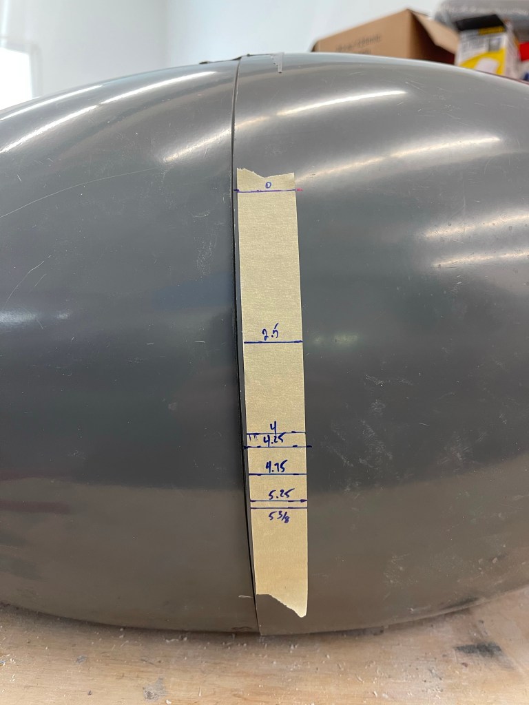
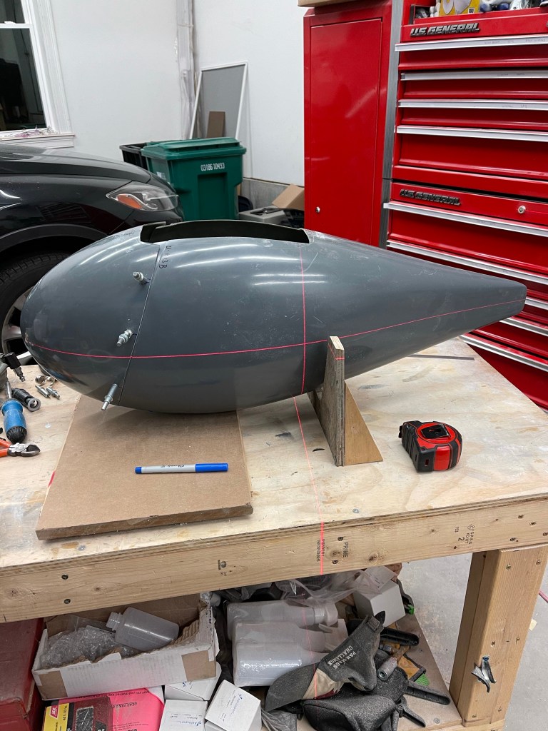
This section is very similar to the main gear fairings in that you find the center point of the aft point of the fairing, extend this centerline to the front of the rear pant, then put the 2 halves together and drill #40 holes along the flange at the specified distances. I used a piece of tape with the distances marked out and taped it along the fairings to mark the drill locations. You then use the same “V” wedge that was used on the main gear to help prop the fairing up so the height of the aft center point is a specific distance above the table. This measurement was then transfered to the front using a laser level and double checking with a square.

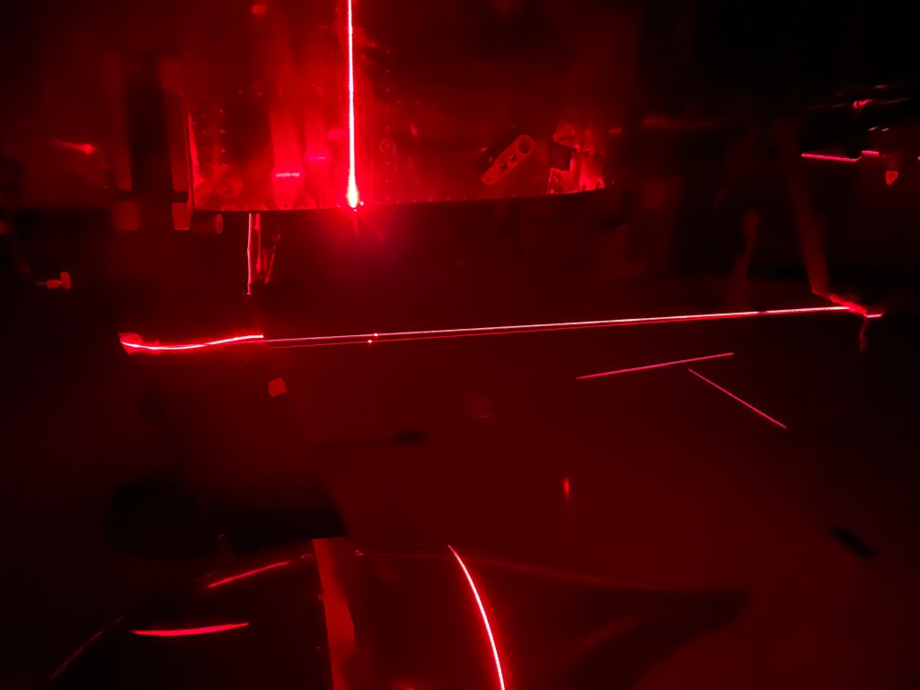
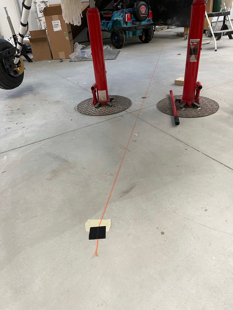
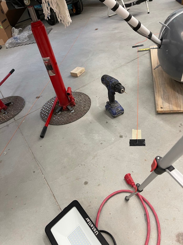
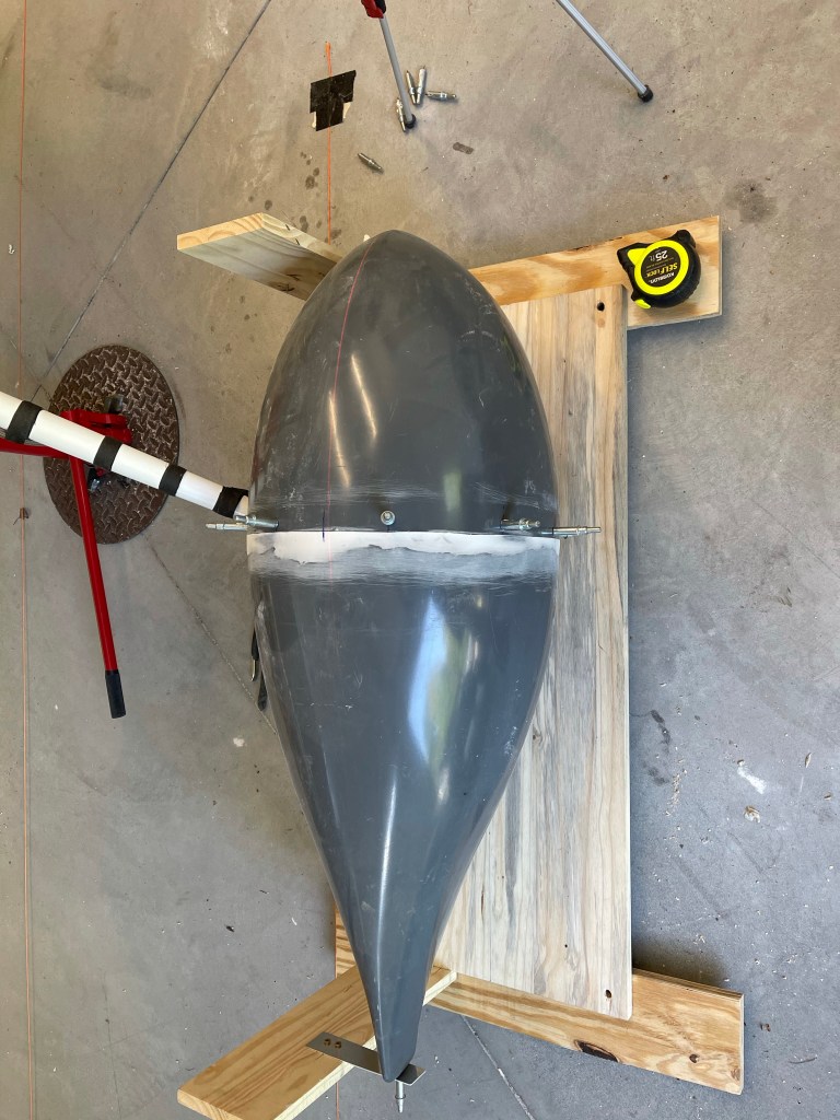
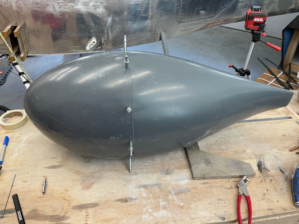
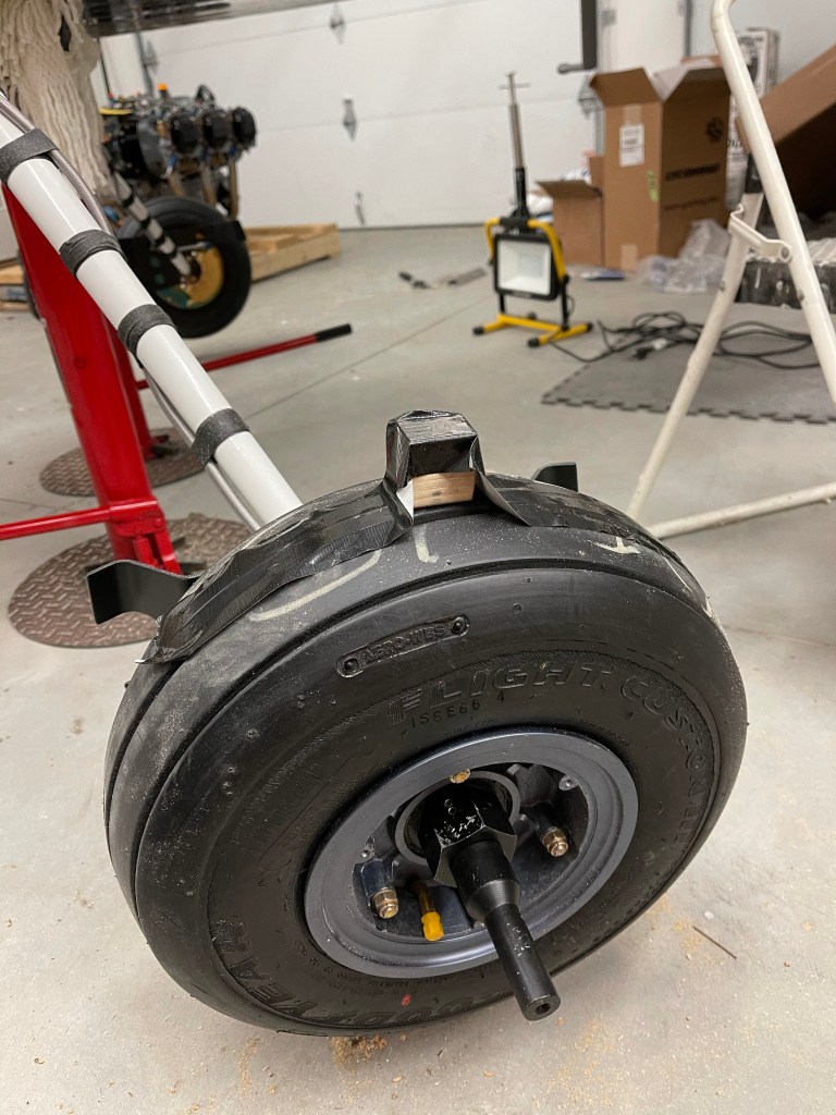
It’s then time to start working on fitting the faring to the nosewheel. One thing that I did that wasn’t outlined in the plans was to mark the location of the nose fork on both sides and extend those line rearward.. As you can tell by the tape and multiple lines, this did take a couple of iterations to get right. I ended up using a laser level to mark them after aligning the beam with the forks. A wooden spacer is also taped to the top of the tire.

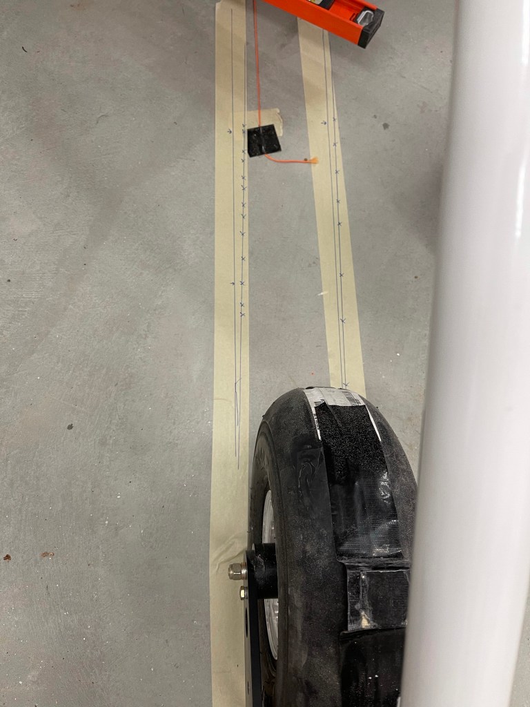
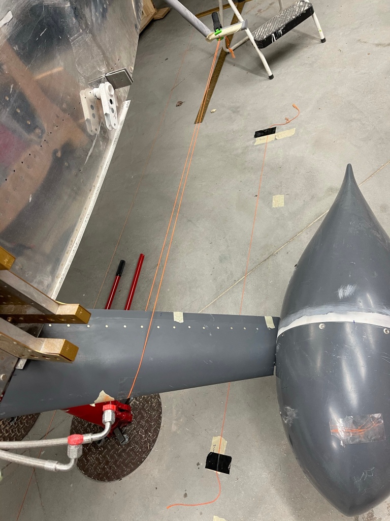
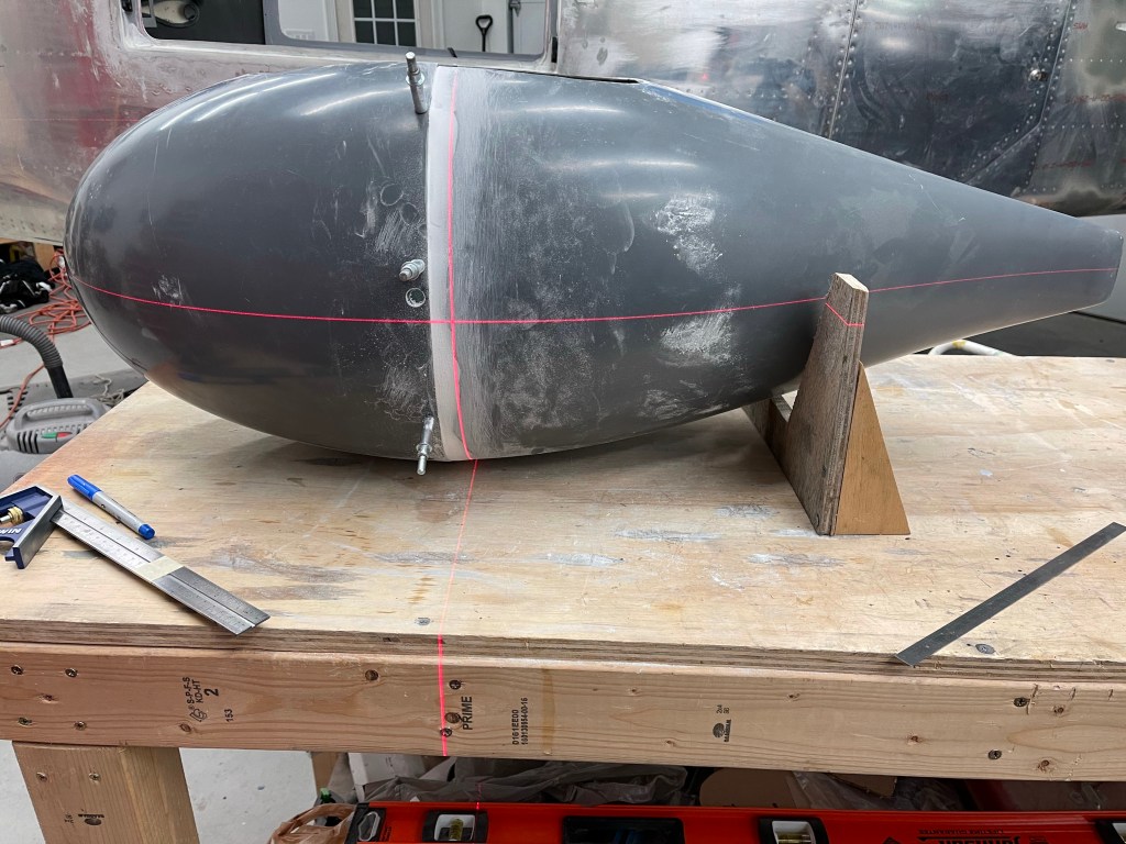
I then marked the center point between the 2 extended nose fork lines and used that location, along with my laser level to make sure that the fairing was always inline with the tire. I’ve still got the plane up on jacks and there is no weight on the front tire, but it’s on the ground enough to not allow it to swivel.. So this mark shouldn’t change as I proceed.

Aligning the faring to the centerline of the nose wheel.

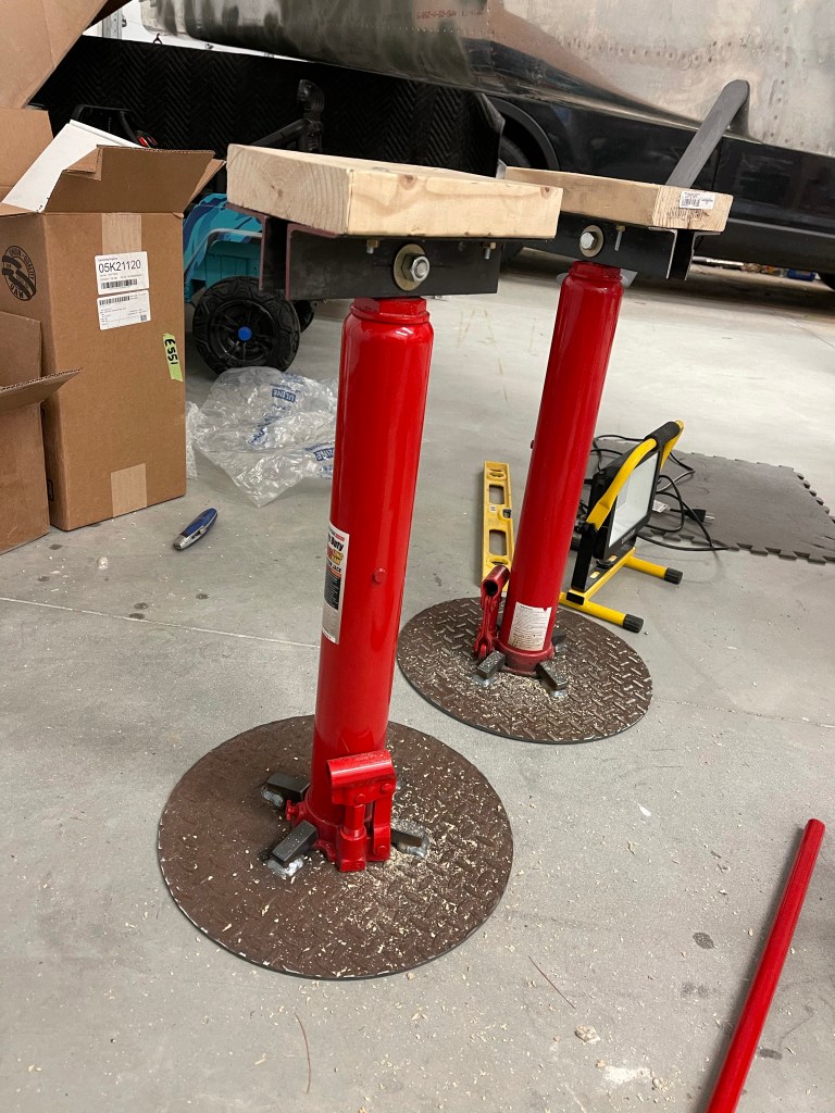
I reused the “V” wedge that I had made and repurposed it to hold the center point of the fairing at the proper height from the floor. Very similar to the jig I used for the main gear. Later, I will cut the V wedge in half and use it on both the front and aft holes of the fairing.

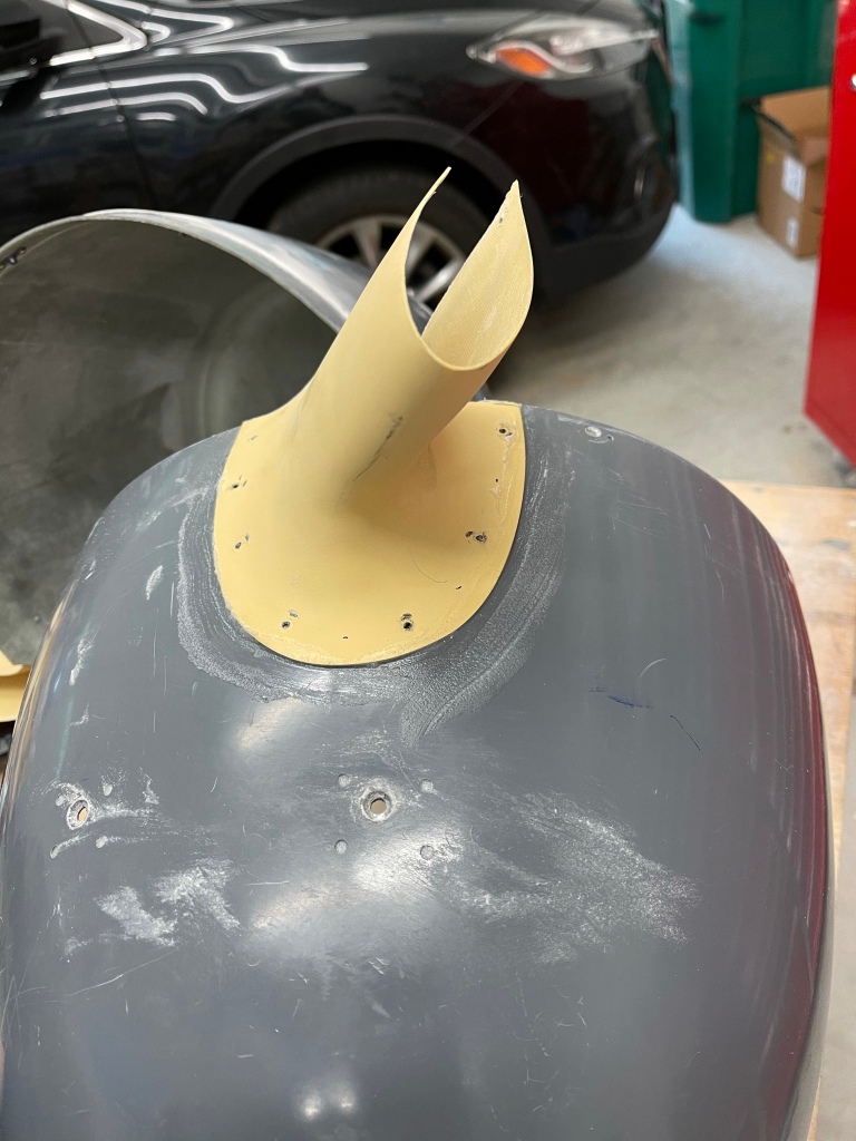
I then followed the plans to drill a 1.5″ hole into the front fairing and trim the tangent lines to allow clearance for the nose gear leg. Once that was done, I was able to file a little bit more along the edges and get the front re-cleco’ed to the rear.

Front fairing mated up with rear fairing

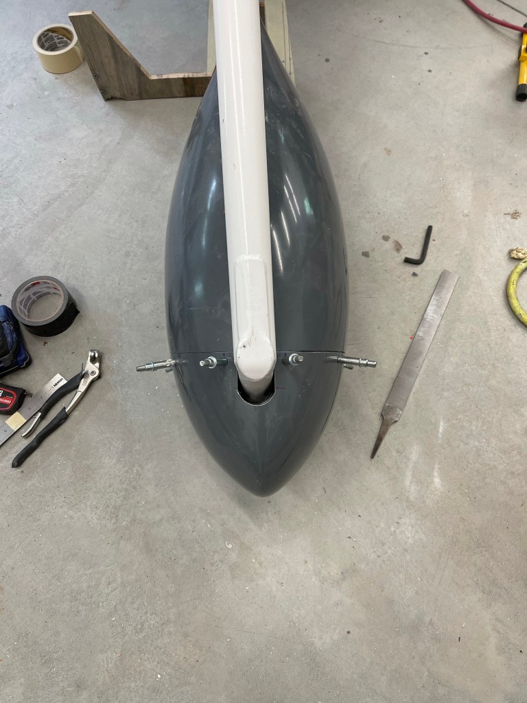
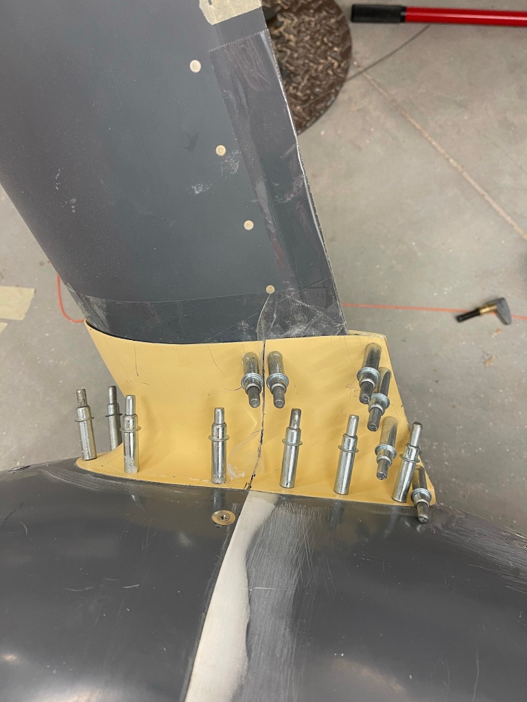
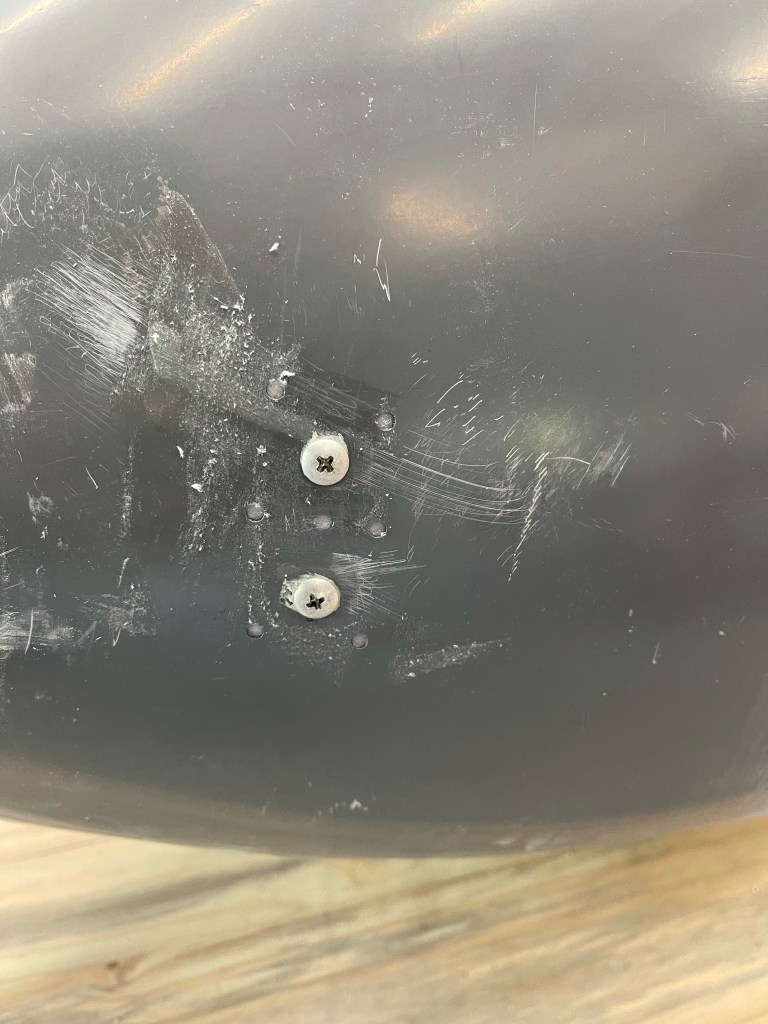
Then after making sure the front and aft locations of the fairing were at the proper height from the floor, you move on to drilling the screw holes into the fairings for the fairing brackets. These ones seemed to be more of a pain compared to the main gear as I had a hard time getting a light from the inside to cast a shadow that I could see on the opaque fairing.

Fairing bracket holes drilled (on left side)

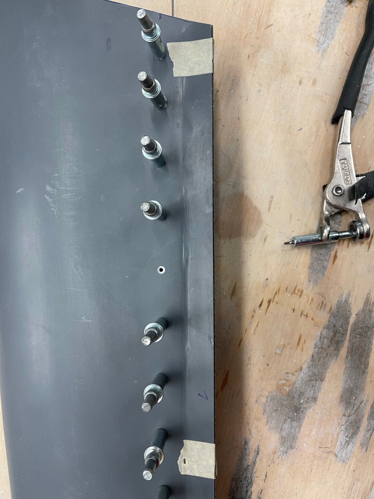
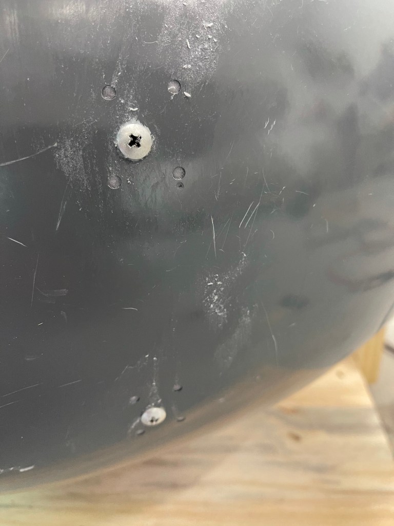
Once again you repeat the main gear procedures for squirting a flox/cabo mixture around the fairing brackets and screws to build up the area inside. I, once again, drilled small holes around the perimeter of the screw hole and used a syringe to squirt in the mixture. Below is a shot of the fairing bracket screwed into place and the hole drilled for a nose-wheel tug to connect onto the bolt location.

Fairing bracket screwed into place.
Outside look at the fairing.

The 2 halves are then joined using screws after final drilling, countersinking, and installing nutplates.

Nosewheel in place all screwed together
Closeup of the tug access hole to the nosewheel bolt.

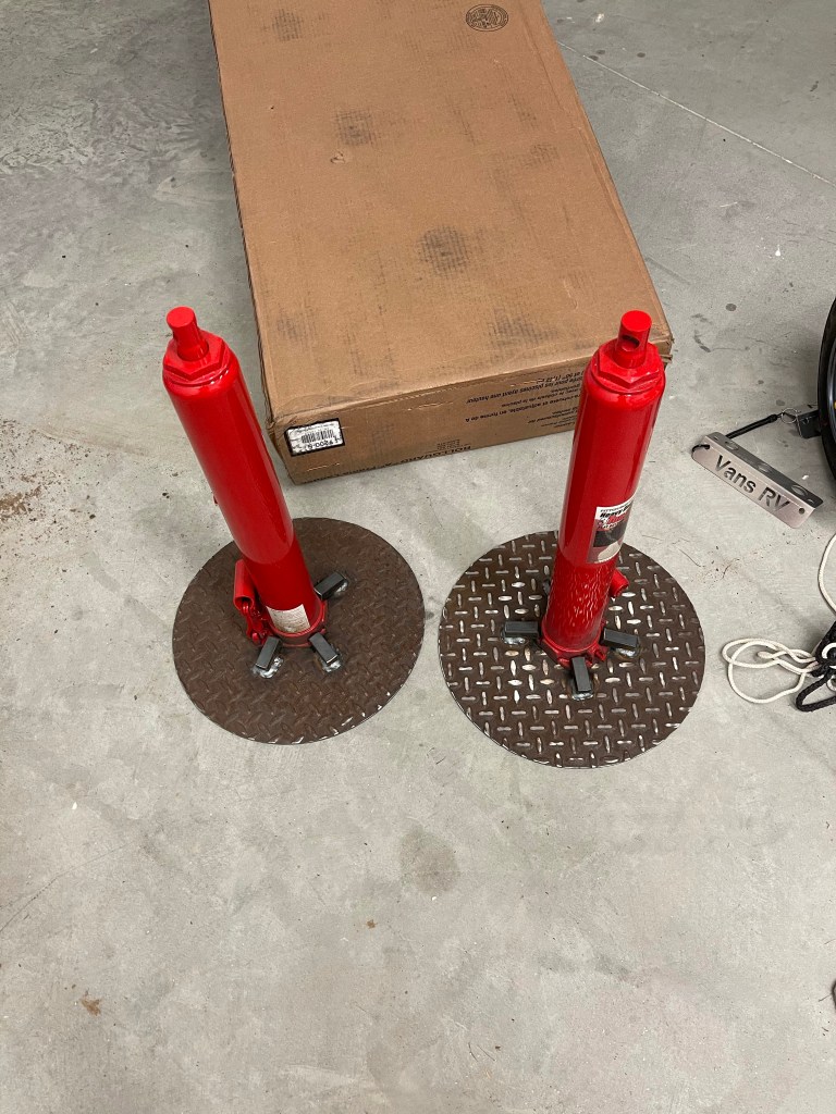
I also decided to use these metal tug guards https://www.flyboyaccessories.com/product-p/73301.htm I recently saw come up for sale. This will help protect the fiberglass fairing and the paint job from getting all dinged up when trying to connect and disconnect a tug/towbar. Might as well install them now while I’m working on these fairings. These were matched drilled to the supplied backing plate. All that’s left now is to countersink, spread some flox/cabo on the backing plate and rivet them in place.

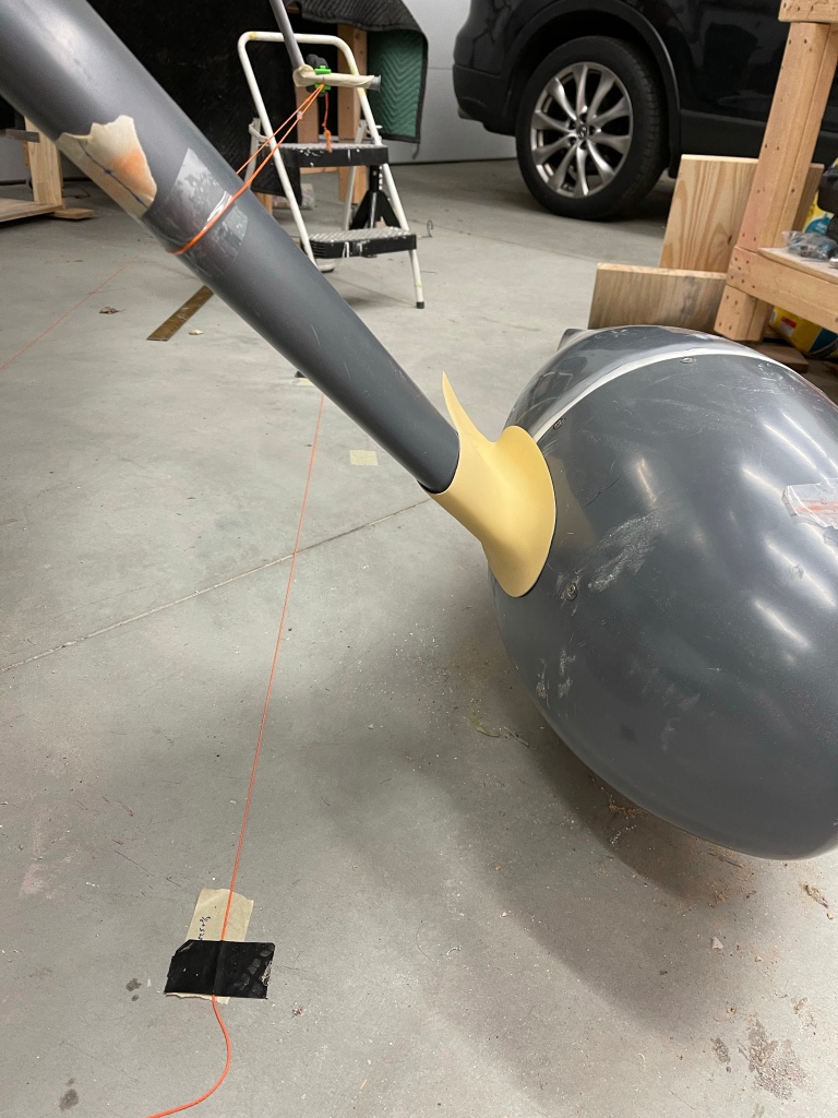
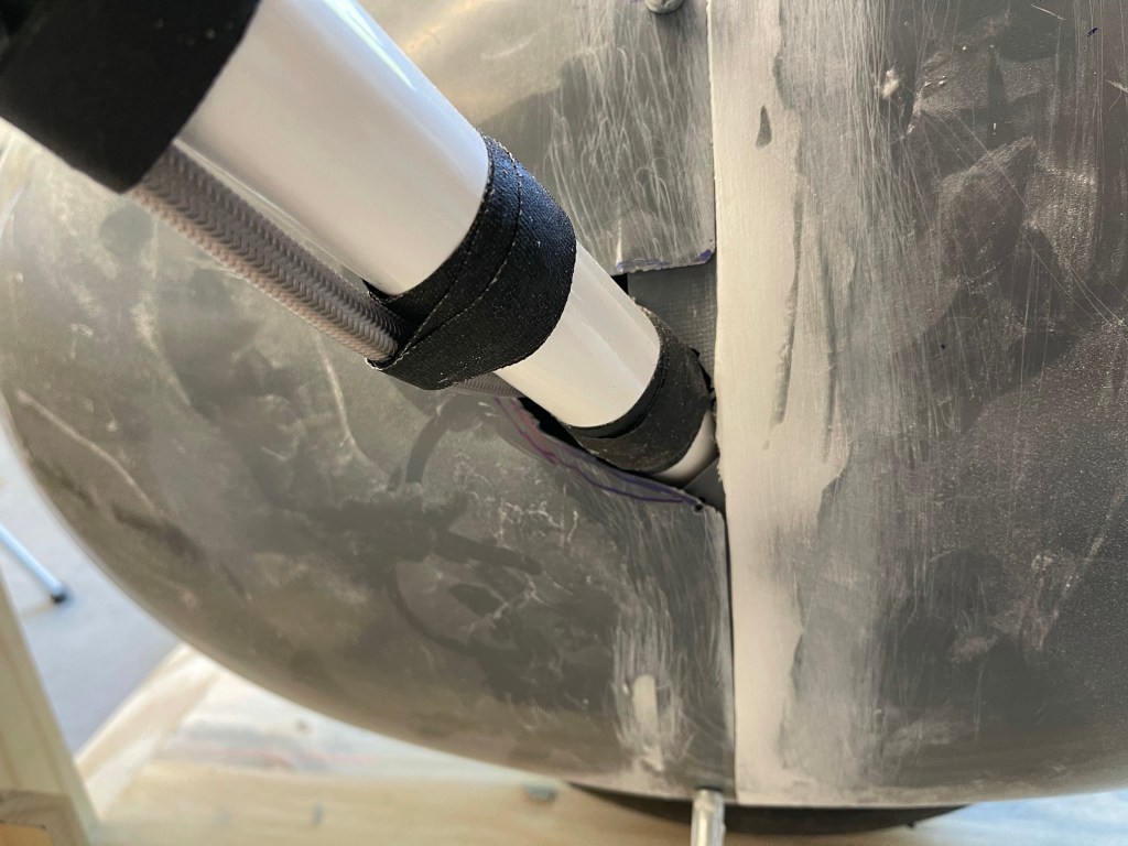
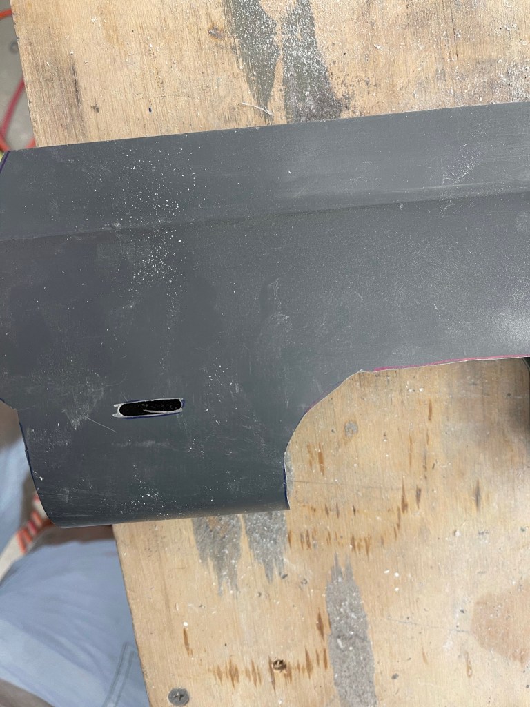
I then set out to get the nosewheel gear fairing going. These are also similar to the main gear leg fairings. A template is used to cut the fore and aft edges and also the U shaped cutout . Here you see me cutting away a slot for a hose clamp by first drilling 2 holes and then removing the material between the holes on the tangent lines.

Start by drilling holes at the ends.
Then remove the material between the holes.

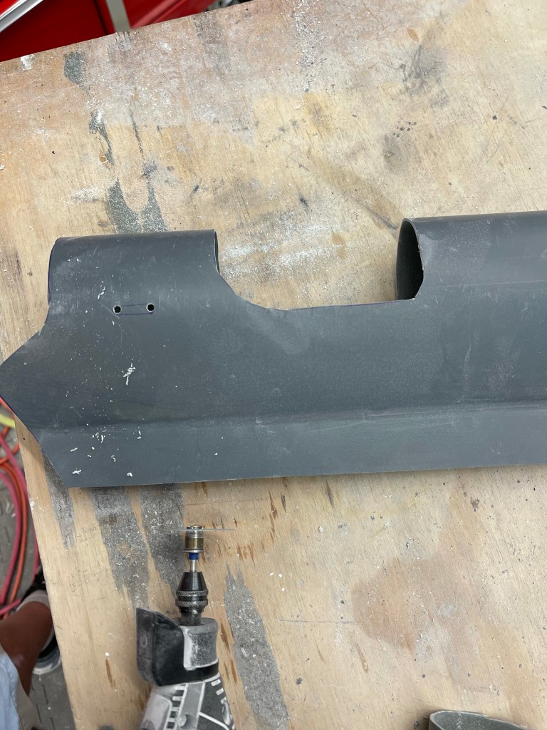
The fairing was then put into position. Some additional trimming was needed at the interface to the nosewheel fairing, and some more still needs to be done, but this is close enough to start on the hinge along the aft edge.

Test fit of leg fairing.
Pretty close trim.. still needs some more trimming/sanding to allow nosewheel to caster around it.

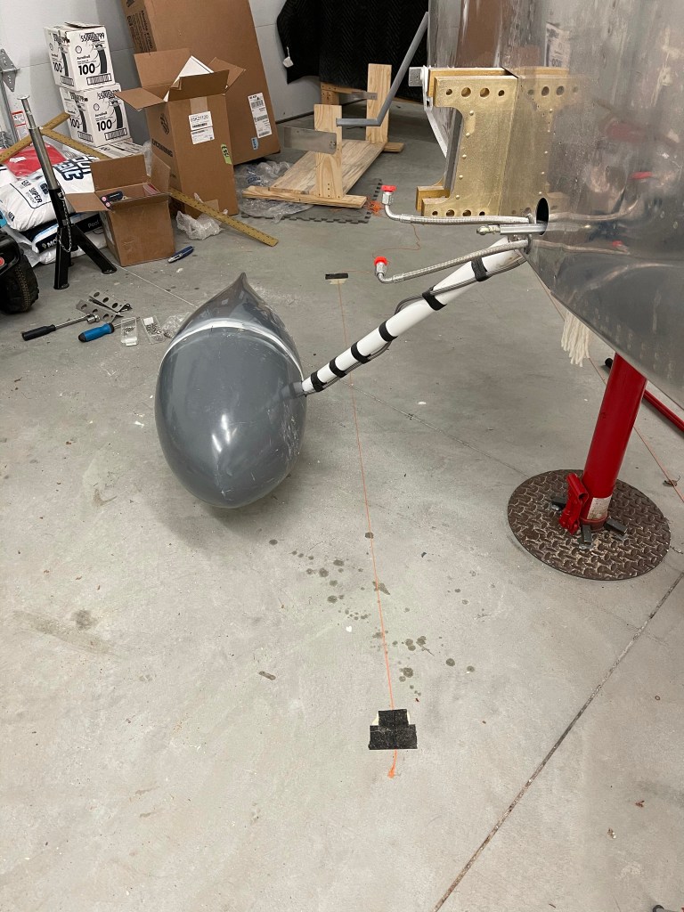
I’ll need to final trim this after I take the plane off of the jacks, as I’m not able to swivel the nosewheel just yet without worrying about the plane falling off the jacks.

Intersection Fairings

As I previously mentioned, a result of splitting the lower intersection fairings and bonding them to the wheel pants has some implications. It’s important to not allow airflow to get underneath the rear fairing half. If that were to happen, it would rip it right off the airplane. So I took some scrap material from cutting the gear leg fairings to use as a flange for the rear half. I cut about a 1″ piece and let approx. 3/8″ of a flange protrude. On a couple of the curved areas, I used a heat gun to contour it to the intersection fairing.

Flange in place

Below you can see both flanges in place and taped up so that no epoxy sticks to them.

I then laid up several layers of fiberglass cloth over the flange and attaching to the forward intersection fairing. This essentially will create a :”tab” for the flange to mate to and keep both the forward and aft sections together.

Another angle of the fiberglass layup.
Curing.

Once that was cured, I separated the two halves and permanently bonded the flanges in place with flox and cabo.

Flanges bonded in place.

A couple of shots of the resultant tab that the flange sits in (prior to any trimming.)

This should provide a solid interface between the forward and aft intersection fairings at the split.

Leg and Intersection Fairings

I didn’t take any pictures of the start of this process, but you basically cut a paper template out of the plans and tape it to the fairings as instructed to mark and make the top and bottom cuts that align to the bottom of the fuselage and the wheel pant. I then placed them on the gear legs to test the fit.

Pretty good initial cut against the wheel pant.

You then cut the piano hinge to length and start marking where it will go to hold the trailing edge together. One slight deviation from the plans was to mark out the drill holes on the hinge and actually drill them with a 3/32″ drill ahead of time. The plans want you to drill through from the outside, but that goes back to the times when these fairings weren’t gel coated and were transparent. I then used the undersized holes in the hinge to match drill #40 into the fairing from the inside with a right angle drill.

First hinge mostly match drilled
Right angle drill used from the inside to match drill the hinge
Countersinking for flush rivets

You then re-install the leg fairings and insert the hinge pin, which is sort of a PITA. Once that task was over, the plans walk you through how to align the fairings properly. Getting this wrong can cause yaw, so you want them as perfectly aligned as you can. The plans have you wrap a string around the leg faring and clamp it to the step. I also feel that that plans walk you through placing a displaced centerline mark at a random location.. I basically reused the string I already had on the floor from the wheel pant install. The issue I ran into was my location.. and just some random location, as mentioned in the plans, isn’t the correct location when the string is perfectly level. So my advice would be to level the string, then use a plumb bob to mark the forward location of the string on the floor. Then duplicate the measurement from the airplane center line behind the step. Place the string that is the displaced centerline of the aircraft and use a plum bob to transfer the location to the step. You then move the aft part of the string to this mark on the step so the string ends up both level and parallel to the aircraft centerline.

Getting the string in place
Using a laser level to verify the string is perfectly level.
End result of the string level and parallel to the Center Line

You then adjust the rotation of the fairing until there is an equal distance between the trailing edge of the fairing and each side of the string.

Proper alignment.

To lock this positioning in place, you move on to install the intersection fairings. I used the intersection fairings from RVBits instead of the stock ones, which need lots more work. The lower left fairing was slid on using care to not change the alignment, which of course was re-checked multiple times.

Lower intersection fairing in place.
Front view.

I’ve decided to bond the lower intersection fairings directly to the wheel pant instead of using more screws to hold them in place. Doing this will require cutting these intersection fairings where the wheel pants separate from each other. It will also require me to add a flange onto the rear pieces so they stay locked in place under the front pieces with no way to get airflow under them.

I drilled a bunch of holes in prep to bond the 2 surfaces together.

The below picture was taken after I started taking clecos out, but I used a laser level to mark the fairing at the wheel pant split. I also decided to add a couple of additional clecos up at the top of the intersection fairing on either side of the cut. I did the same thing for the inside line as well (not visible here).

Cut line marked.

I then took things apart, cut the intersection fairing taped up the leg fairing so things wouldn’t stick together, and mixed up an epoxy/flox/cabo mixture putting things back together and letting them cure overnight.

All put back together and curing overnight.

The next morning I took the wheel pants off and the separation of the intersection fairings worked out well as shown below..

Rear fairing.
Front fairing.

A couple of pictures of the wheel pant put back together.

I then placed and drilled a small hole for clecos (for now) and placed the upper intersection fairing into position. This will later also attach to the wing root area.

Wheel Pants Part 2

With the jig leveled off and touching the bottom of the tire, the rear of the gear pant was put into place to trim a small amount to accommodate the gear leg. You continue trimming until the gear fairing extension hole is coincident with the aft “step” of the flange on the pant. then just make sure that you have some small gap all the way around the gear leg.

Rear pant in place

Then the same thing is done with the front pant. Trimming until you can fit it on the rear and have a small gap around the gear leg itself. One thing I did a little different on the right side (the 2nd one I worked on) was to mark out the extended centerline sooner and have the alignment of the pant at least close to where it needs to end up. On the left, I was slightly off and ended up trimming more than I should have. Nothing that the intersection fairing won’t cover up, but still a little too much. The plans don’t really have you aligning things to the centerline until after the trimming is done..

Front joined to rear to start the alignment.

I then dropped a plumb bob on the centerline of the plane and marked it with a string.

Aircraft centerline

I then took a square and measured a random distance over that would provide a good displaced centerline reference closer to the pant/jig itself. I also used a string to mark this on the floor.

Displaced centerline reference

The jig and pant combo was then aligned to the centerline by marking the centerline of the pant in the jig and making sure the measurements from the displaced centerline to the jig centerline matched as perfectly as possible front to back. It’s then that you drill the holes through the pants lining up with the holes in the fairing brackets. This is done by shining a light on the inside so you can see the outline of the hole against the gel-coated fiberglass surface. Once those holes are done and oblonged as needed to align things perfectly.. The area on the inside of the pant, where the screw goes through and mates with the fairing bracket needs to be beefed up with flox. This was done by drilling several small holes around the screw and squirting the epoxy/flox/cabo mixture into them with a syringe.

Closeup of rear screw locations while flox was curing
Closeup of front locations of the screws into the wheel fairing brackets.
Everything all aligned.

You then also beef up the area where the gear extension is with a flox/cabo mixture. After that cures, you take the pants apart and place nut plates for #6 screws where the cleco holes were.

Most of the screws are in place here.

All of the same things were repeated on the right side. Below are some better pics of the trimming reliefs for the gear leg.

Right pant all aligned.
Right pant done too.
Both main wheel pants done!

Wheel Pants Part 1

Another task to do before the engine arrives and gets hung is to install the wheel pants and leg fairings. This step requires you to jack the plane up to get the weight off the wheels. I’d like to get this step done now before the plane bulks up another approx. 400lbs. Otherwise I’d likely end up waiting until the wings are on and jacking it up by the tiedown locations, which means I’d probably procrastinate and have to do this after I’m flying.

You start the wheel pants by sanding the two halves of the pants where they are built up to make them fit together well. The plans then have you trim/sand the front flange as required to get a square fit. This was accomplished by running a sharpie around the circumference of the pant on a flat table. I then trimmed to that line.

Marking the trim line

The next steps have you find the vertical and horizontal center of the aft end of the pant. The use of a laser level helps here.

You then mark the locations to drill holes to mate the two parts as called out in the plans. I used a piece of tape with the various measurements needed to accomplish this paying attention to left vs right as the dimension are different on each side and are mirror images of each other.

Tape with measurements to mark hole locations
All holes drilled and held together with clecos

The next task is to mark the equivalent horizontal mid point on the front of the wheel pant. You use a wooden fixture to help hold the pant into position while making sure the aft end is at the plans specified height. Also making sure to make sure everything is plumb and square.

Aft end at proper height

Again a laser level makes easy work to transcribe this line to the front of the pant. I used the square with the tape mark on it to double check that is was correct.

Now comes the point where you need to jack up the plane. The plan is to place jacks under the main wing spar on either side of the plane and jack up the plane. Then you must make sure that the plane is in flight level attitude as described in the plans. Levels were used to confirm this. I had some adjustable screw-style jacks that I had planned to use for this, but what I found out is that the adjustable height nature of them made for too much wobble side to side, which made me very uncomfortable. The one thing you do need to make sure of is that you’re careful when jacking this thing up entirely off the ground. It can easily fall off the jacks and cause damage or worse injury… So I decided to go buy better jacks that I’ve seen many people use from Harbor Freight and have a local guy weld some bases on so they won’t tip over. I will most likely be using these on at least an annual basis during condition inspections to lift the plane up, so the investment is not wasted.

Jacks with welded bases on.

I then used some steel angle I picked up at the hardware store and a length of 2×6. I make 1/2″ holes on one side to go through the large hole at the top of the jack and a couple of holes to attach the 2×6 to the angle with a couple of bolts per side. I then added padding to the 2×6’s and the end result was much more stable.

Finished Jacks minus padding
Plane up on jacks in flight level attitude. Also note the wooden jig in place for test fitting

I then worked on making a jig to hold the pants into position for me as I’ve seen others do. This will help hold the pant perfectly in place the correct distance to the “floor”, which becomes the top surface of the jig. In each corner there are adjustable feet so I can get things perfectly level.

1 1/4″ spacer taped to the top of the wheel
Setting the proper height above the floor (jig) for each end of the pant.

Up next is to start drilling holes and getting the pants properly lined up on the wheel assembly itself.