In prep for installing the baffle material, I used my go-to method of using construction paper to make templates for each piece prior to cutting the actual material. I targeted 2.5″ above the metal baffle material based on what others have done. I did a few test fits with the upper cowling on to make sure that length seemed like it would work. I tied to make the pieces overlap around the split points in the metal in case I ever need to take the whole assembly apart at a later time.


I then marked the templates with a line along the metal baffles to mark their position for reinstallation later on. I also marked out a line with enough edge distance for drilling 1/8″ holes to pop rivet the baffling material to later.
Once that was done, I removed the templates and cut out the material one piece at a time. I tried to cut such that the natural curve from the material roll would be in the direction I wanted the material to lay.


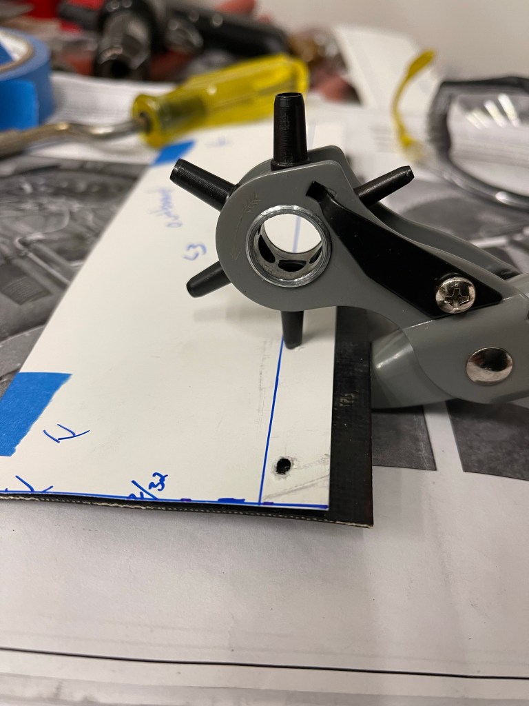
The method I found worked the best to punch holes in the baffle material was to first tape the template on the piece.

I then used the previously drawn line to place the template/piece assembly in place relative to the metal baffle making sure I had enough material for the overlap spots to the adjacent piece. I would use a drill to cut away the construction paper enough to mark the spot of the hole to be punched. I did the first 2 holes, then punched holes.. put the piece back into place with clecos and then drilled the remainder of the holes so I didn’t have to try to hold the assembly in position for the entire sequence.
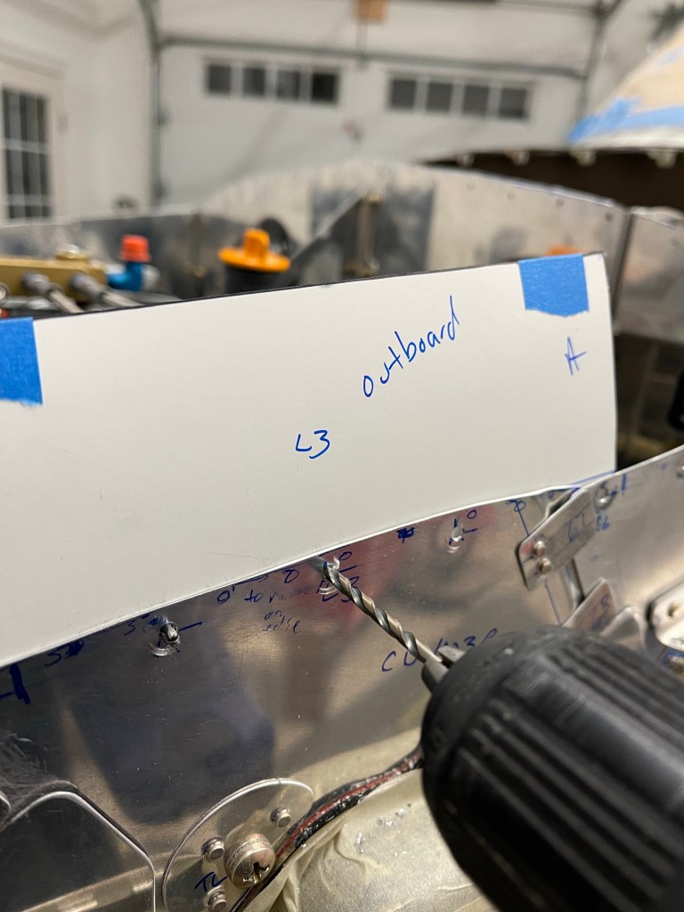

I then used a punch to make the hole in the proper spot in the silicone baffle material.
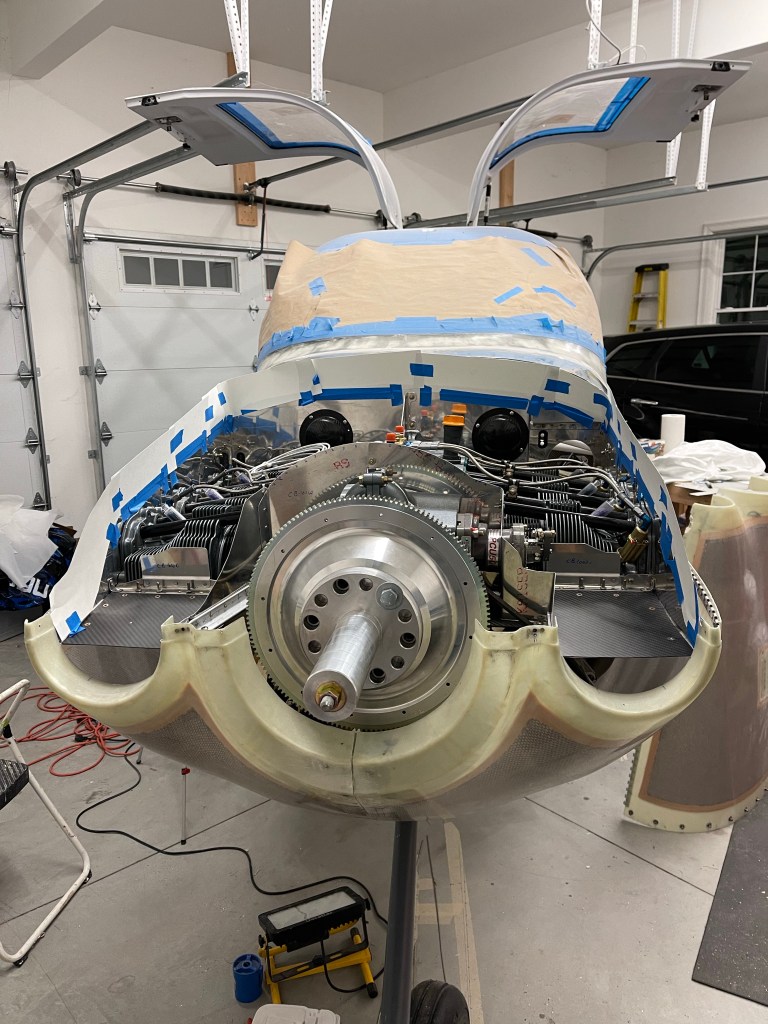
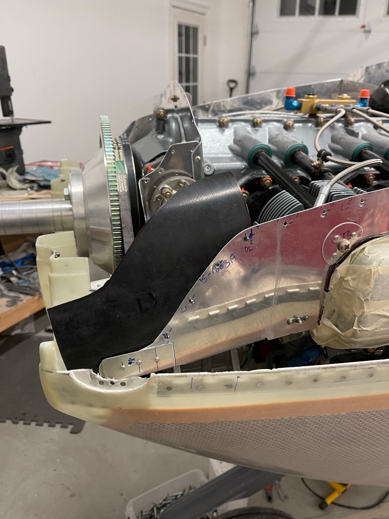
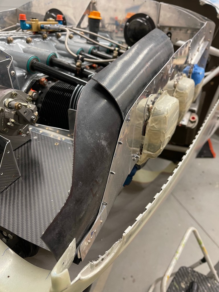
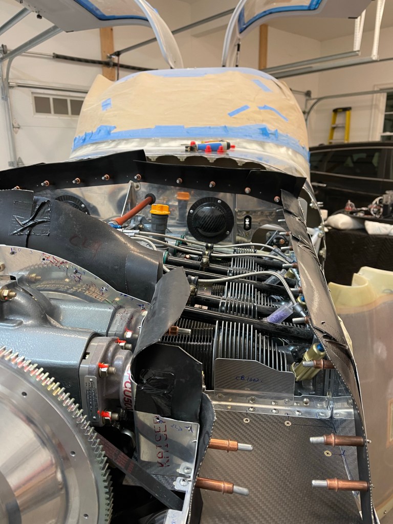
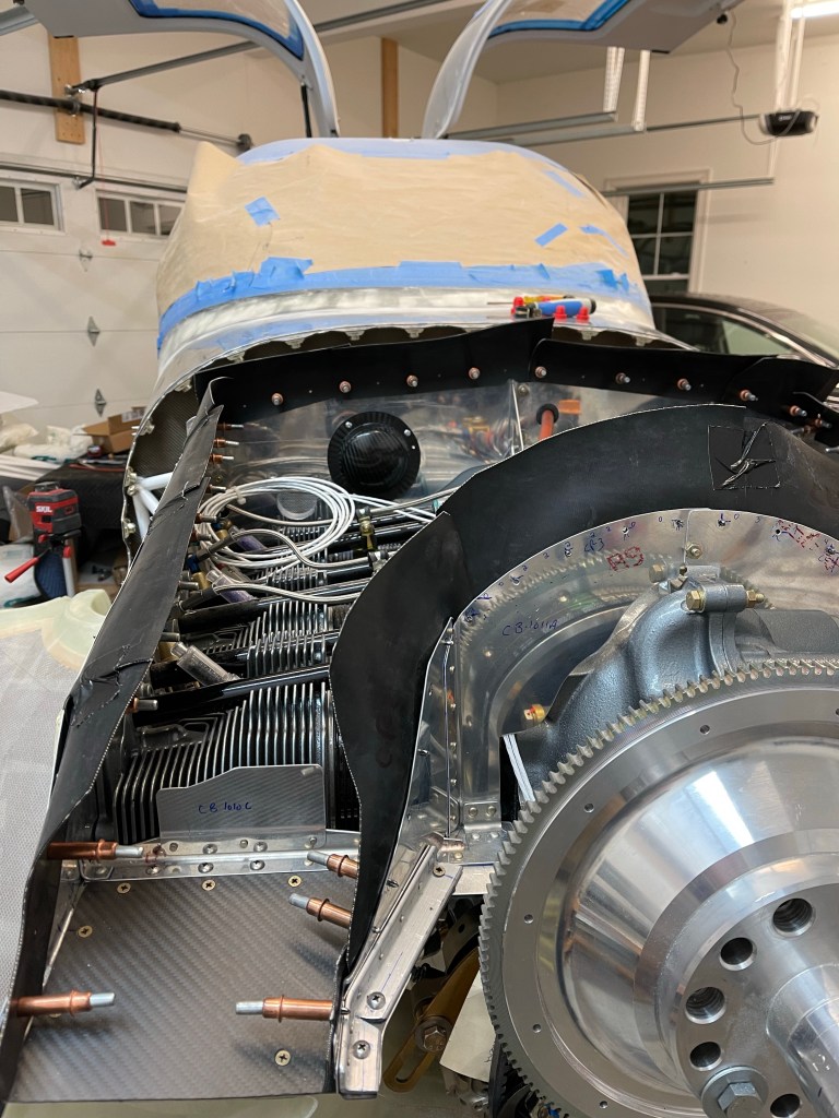
Below are some pics of the final install. I did have to take some of the curl out of these pieces as they tended to curl inwards a little too much. I rolled each piece by hand in the opposite direction and sat some weight on the pieces to take some of the curl out. I also used some duct tape to hold adjacent pieces somewhat together. This will simulate the eventual RTV that will be used to hold everything together.


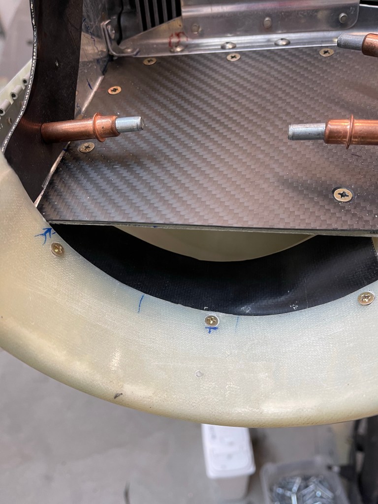
I then did something similar to the plans for the stock cowl to bridge the gap between the air intake tubes and the cowl. I used the metal strip material provided and curved it to match the round intake shape of the cowling. I then matched drilled 3 holes for #6 screws to hold this to the cowl. I cut some additional baffle material and used contact cement to adhere to the metal strips.

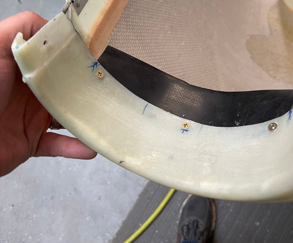
Below is a picture of the iniital test fit of this strip/baffle material fit. It seals up the small gap between the cowling and the intake tubes by resting on the inside of the air intake tube. I’ll likely trim this piece a little more for a better fit. Note also that I was sort of holding this in position to take a picture so the alignment is a little off, but you get the gist of what I am trying to accomplish here.