A quick pic of the ANL bases installed on the firewall as I finished up placement of most items. There will still be a few others, but I’ve got the bulk of them done prior to installing the Firewall insulation and engine mount.

I also got my oil separator from Anti Splat Aero and the first batch of Air Conditioning parts arriving.


That allowed me to place the 2 pass throughs for the AC hoses in the firewall prior to continuing. After a bunch of debate, I decided to route them down the right side of the aircraft. A lot of people route them down the tunnel, but it gets pretty crowded in there, especially up in the front, and you’re also competing against rudder cables and elevator push rods. So I decided to do the right side. The fittings are placed closer to the right side of the firewall.

Now that the bulk of the items were placed on the firewall, I made a template for the Lavashield insulation material. I really had planned on using fiberfrax with stainless foil over the top, but I was fighting lots of competing priorities that led me to use this instead. On this template you can see I cut out an area for the recess. I also made another template for the recess so it would be one piece.

Below is the one piece lava shield for the recess area. The larger piece will go over this making the end result look nice.

The larger piece of Lava shield mostly stuck onto the firewall with some major holes cut out. I left the backing on the upper part so that I can rivet the upper forward fuse prior to sticking it down.


I then started placing the major components back on the firewall now that the insulation is in place. Later, I cut out spots around the engine mount locations, as there should be nothing between the mount and the frame. Other things go right over the insulation.

Engine mount held in place for a quick check.

Another thing I tested out is my control servo for the oil cooler. This will allow me to control the amount of air going into the oil cooler with a knob on the panel. This will come in handy in the winter months where I can close it down a bunch and keep the oil temp right at 180 degrees.
Here’s a shot of the entirety of the plans.. followed by where I currently am in the plans. While I’m quite far along, I think I’ve reached the 90 percent done, 90% to go milestone.


After putting all the pieces back on the firewall, I decided to re-pressure test my brake and fuel lines seeing I took the connections apart. While this area isn’t a place I disassembled, I was glad I did as I found a minor leak at the post filter.

Another task prior to riveting the upper forward fuselage in place is to start routing the Air conditioning hoses from the firewall. It’s a lot easier to do it now while I have better access. Below is an overview of the hoses (2 of them) that go between the compressor in the engine compartment, through the firewall, and to the condenser on the belly of the plane as well as the evaporator in the tailcone.

Some pics of the AC hose (black hose) routing down the right side.


One implication of going down the right side is getting the hoses all the way to the back. This required me to drill out the right baggage and rear seat pans to re-gain access.. Probably took 1.5 hours to get that all done.. Stinks to have to do this after it was all closed up, but such are decisions to add AC later in the game.

I’ve settled on running the hoses as shown below. The red line depicts the hose that goes from the compressor to the evaporator. The green line depicts the hose from the compressor to the condenser on the belly. For that one, I’ve decided to go across the rear seat front where the hose will be hidden by the flap tube cover, then go into the bay under the rear seat closest to the tunnel, and pop through the rib where the connection comes up from the condenser. I will be adding access panels to the baggage and seat pans to allow access in the future.

I also have received a curved bar for my engine mount to accommodate the Barrett Cold Air Induction sump. Its pictured below in place of the straight bar it will replace. This will provide some additional clearance needed for that sump. I’ve found a local welder to cut the existing bar out and replace with this curved bar. I’ll be picking that up from him in the next day or so, as it is all done and ready.

My ugly mug taking a pic of the battery area to see how good I’ve scraped the primer off of the metal where a battery ground cable will be locally connected to the structure.. 🙂

I then used the crimper to crimp the 2 AC hoses at the firewall connections and tightened them up.


A separate package arrived a few days later containing the shelf for the evaporator along with the scoop and condenser unit for the belly of the plane.


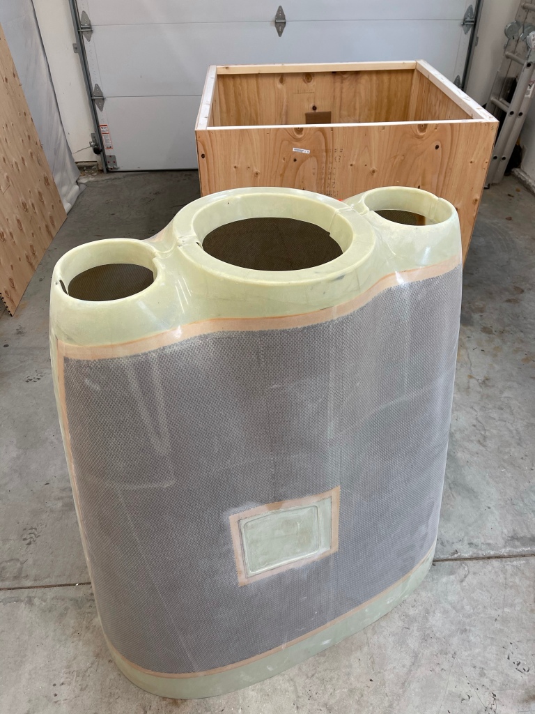
Part of the choice to use the Barrett Cold Air induction sump, involves using a different cowling from Show Planes. It recently arrived and is stored away for early next year after my engine arrives.


After as much up-front planning as I could do, I was ready to rivet the upper forward fuselage in place permanently. Sometimes you just have to get some of these steps done and move on to allow me to continue to make progress. This might mean that I need to be upside down a little bit more as I finish some things up front, but so be it. My wife, along with a friend both helped me rivet the upper forward fuse in place. It was definitely a 2 person job with one person using the rivet gun and the other manning the bucking bar. Below is a pic of my helper today after finishing up getting the riveting done.

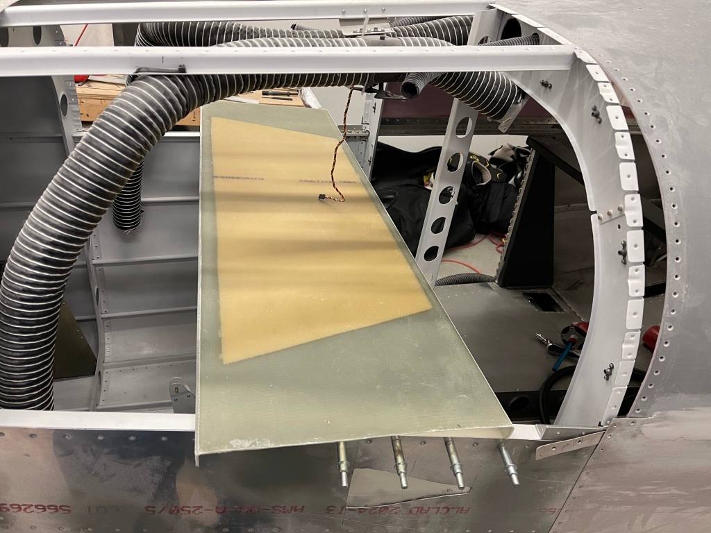
I then continued on to install the center support bar. Prior to doing so, I cut out the center support piece in the overhead switch pod. This isn’t really needed as my switch pod is bonded in and built up all around the perimeter holding it in place. This will allow better access for the nuts as well as the electrical switches etc.. that are planned for up there. It only took 10-15 minutes to get that cut done.

The culmination of the day was bolting the center support bar, which I’ve painted black, into place so I can finish up the fiberglass and interior painting prior to moving to installing the windows and putting the plane up on the gear.

