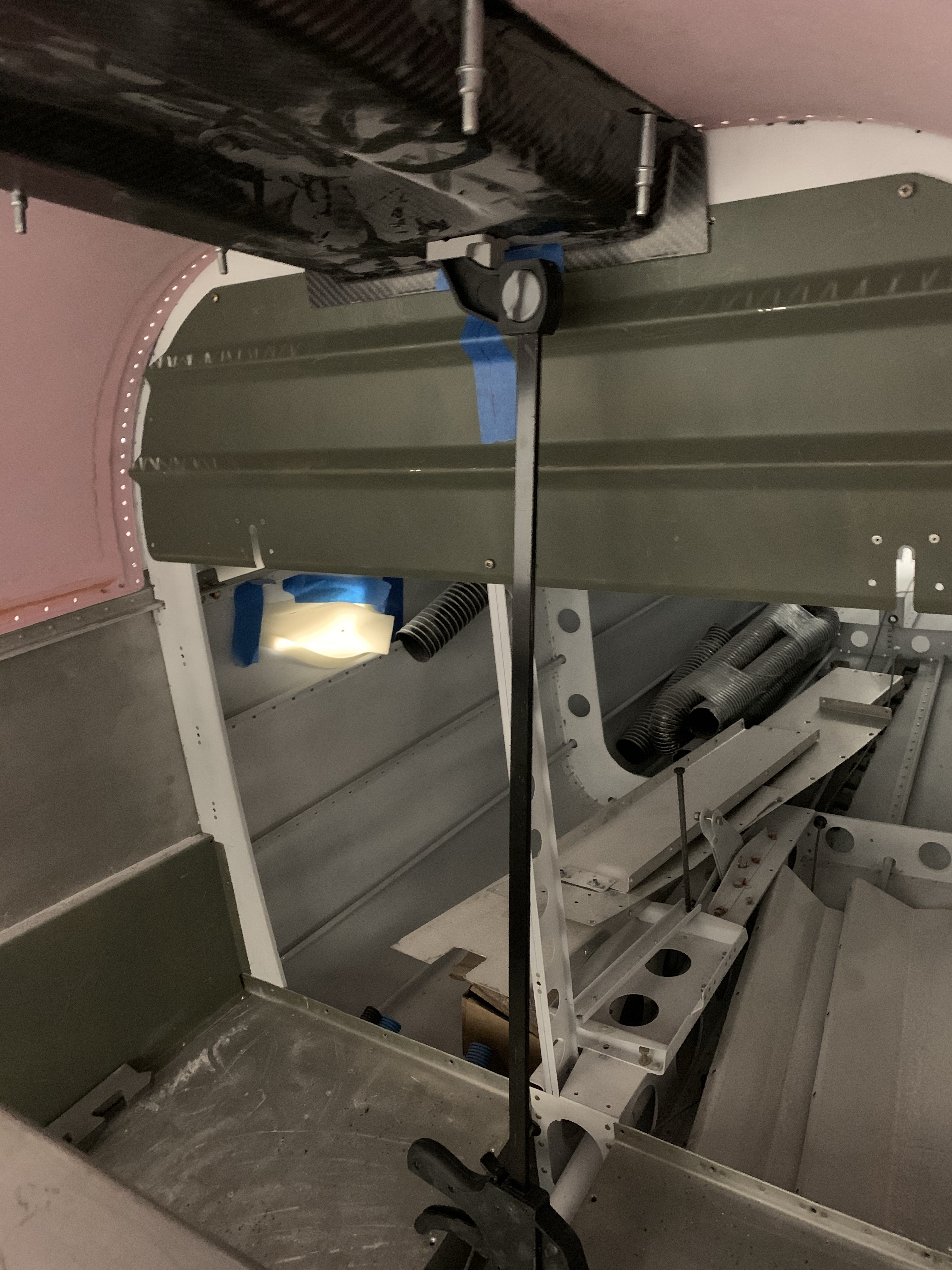
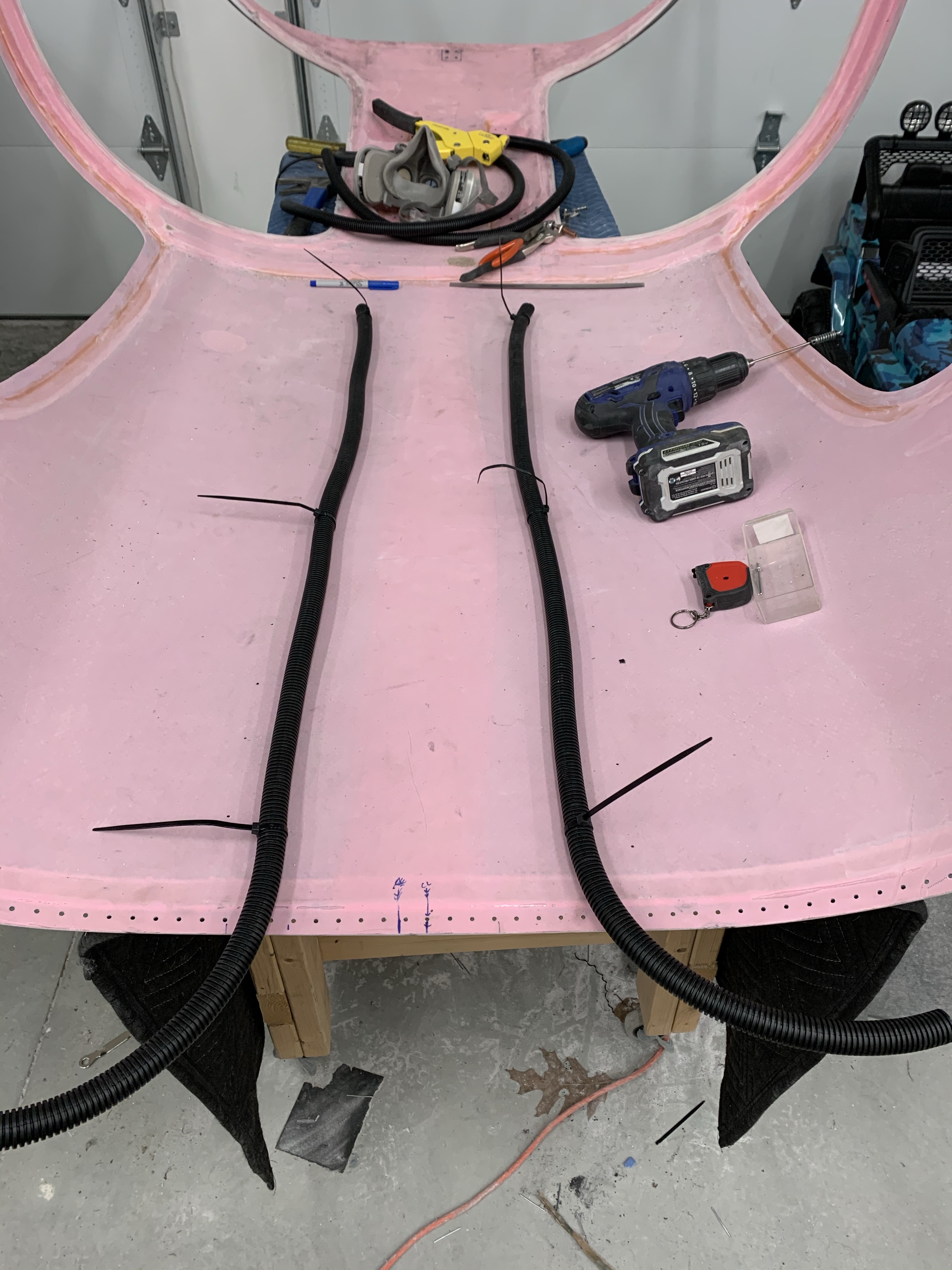
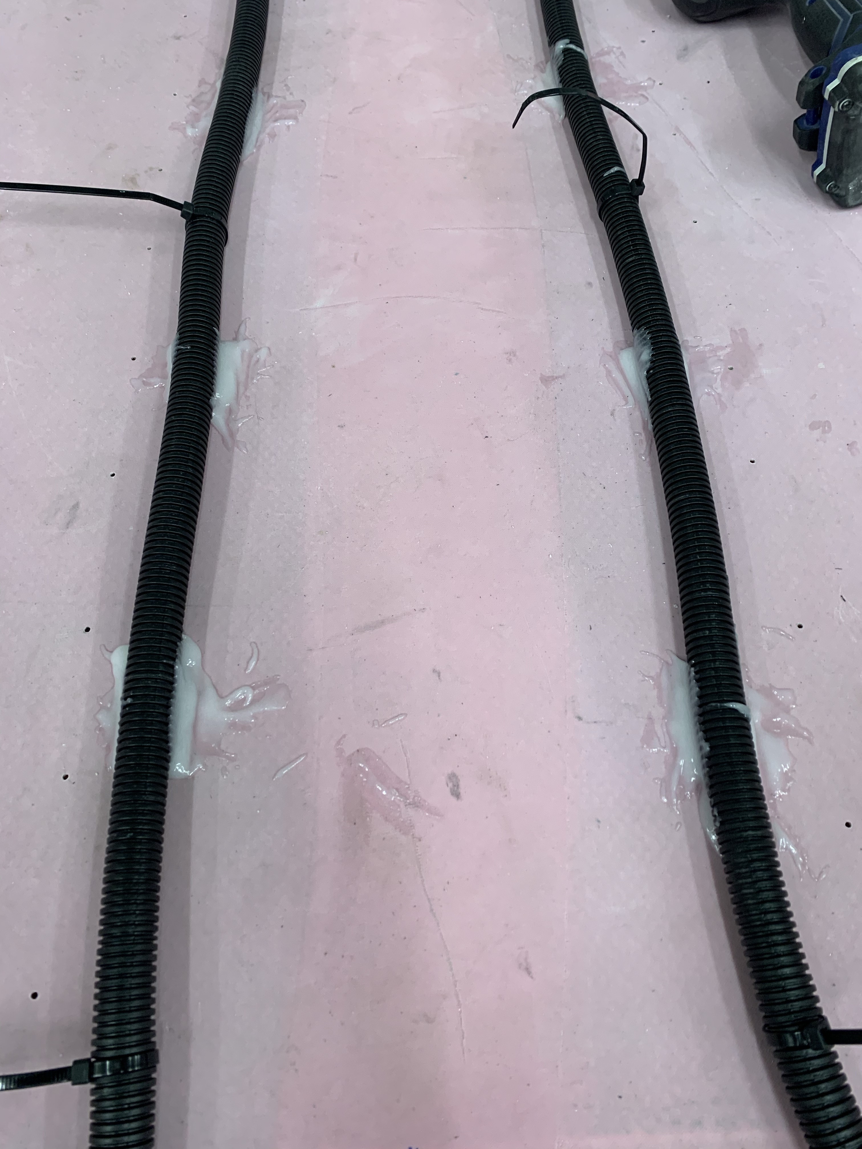
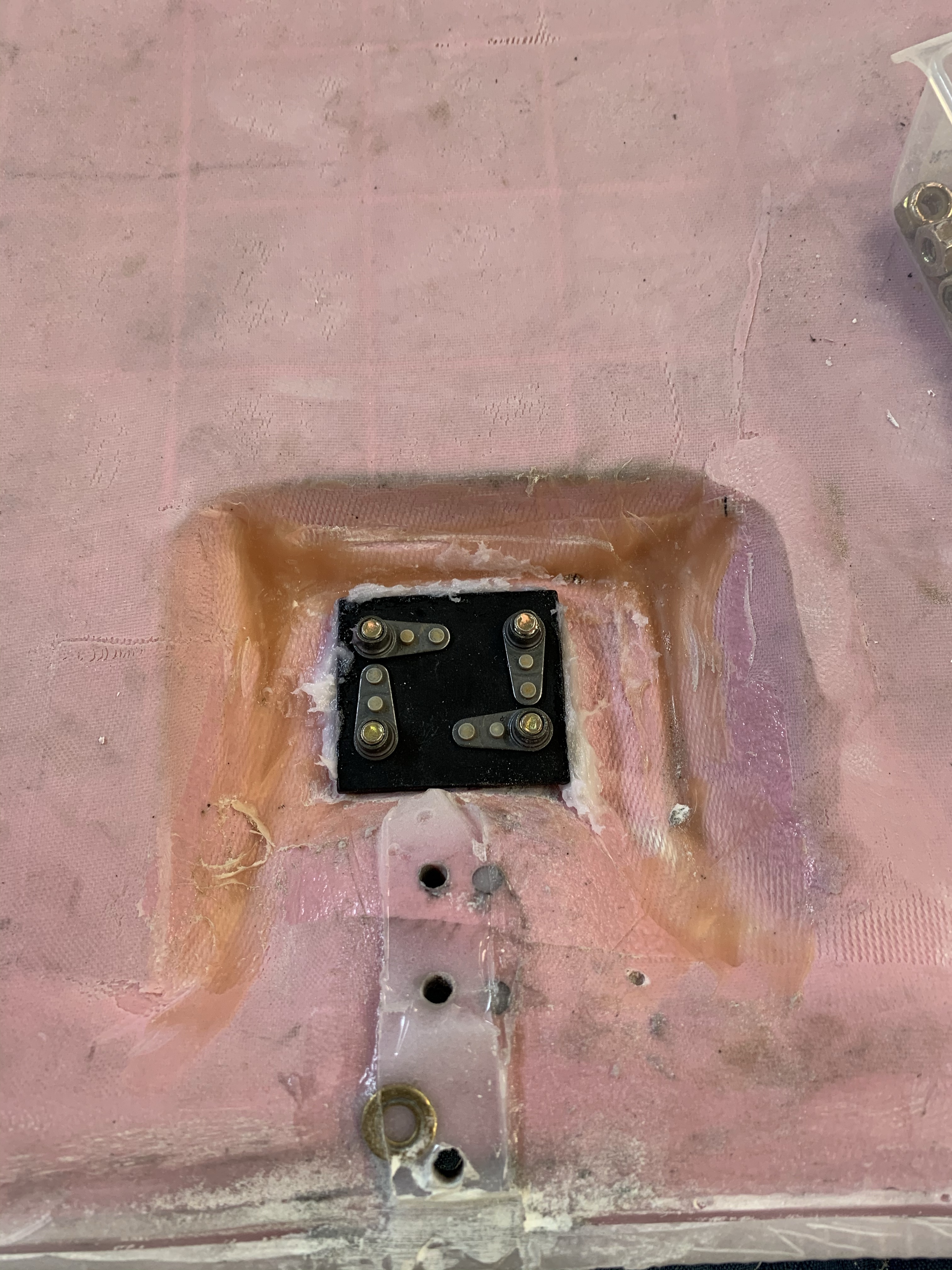
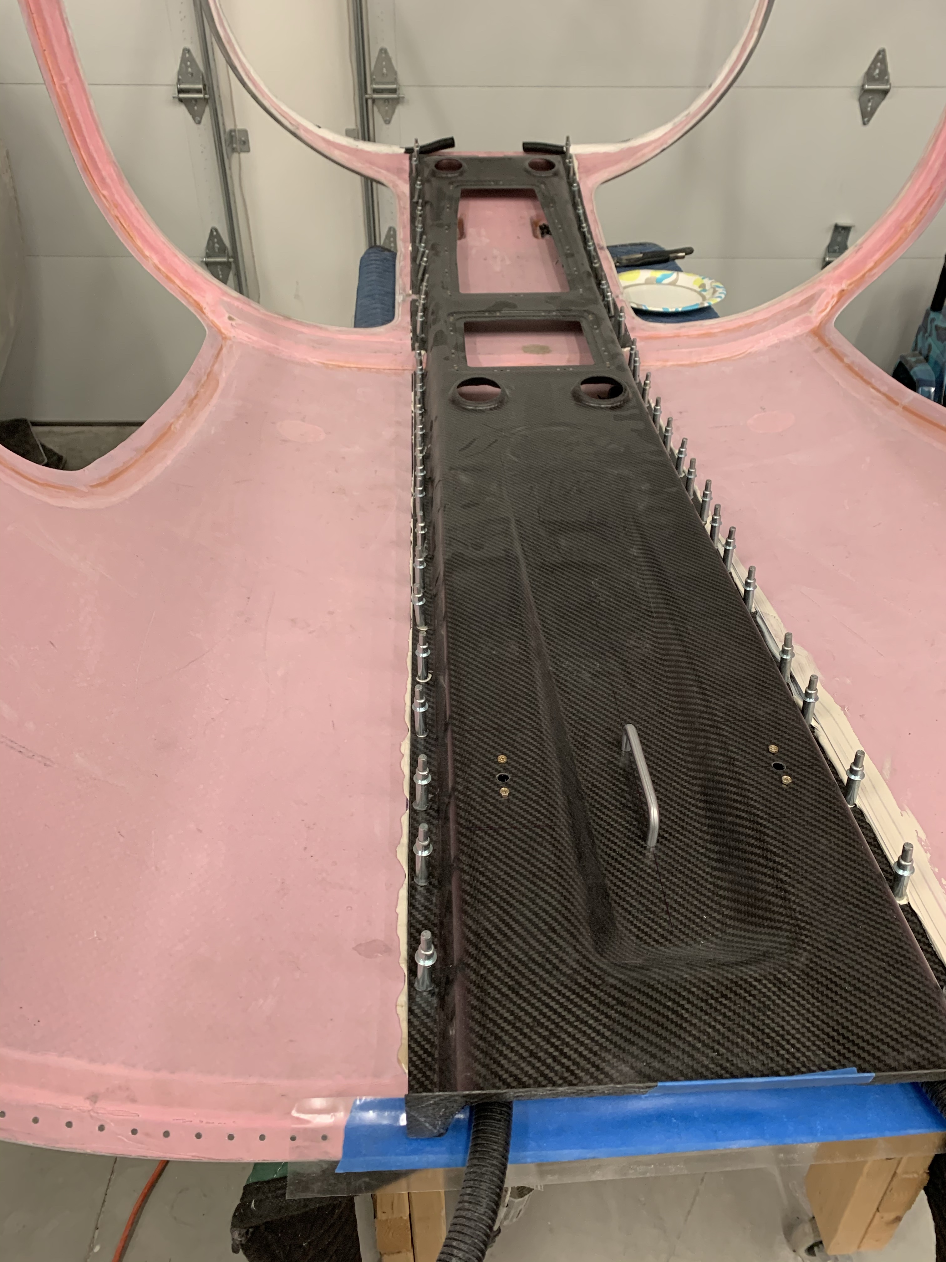
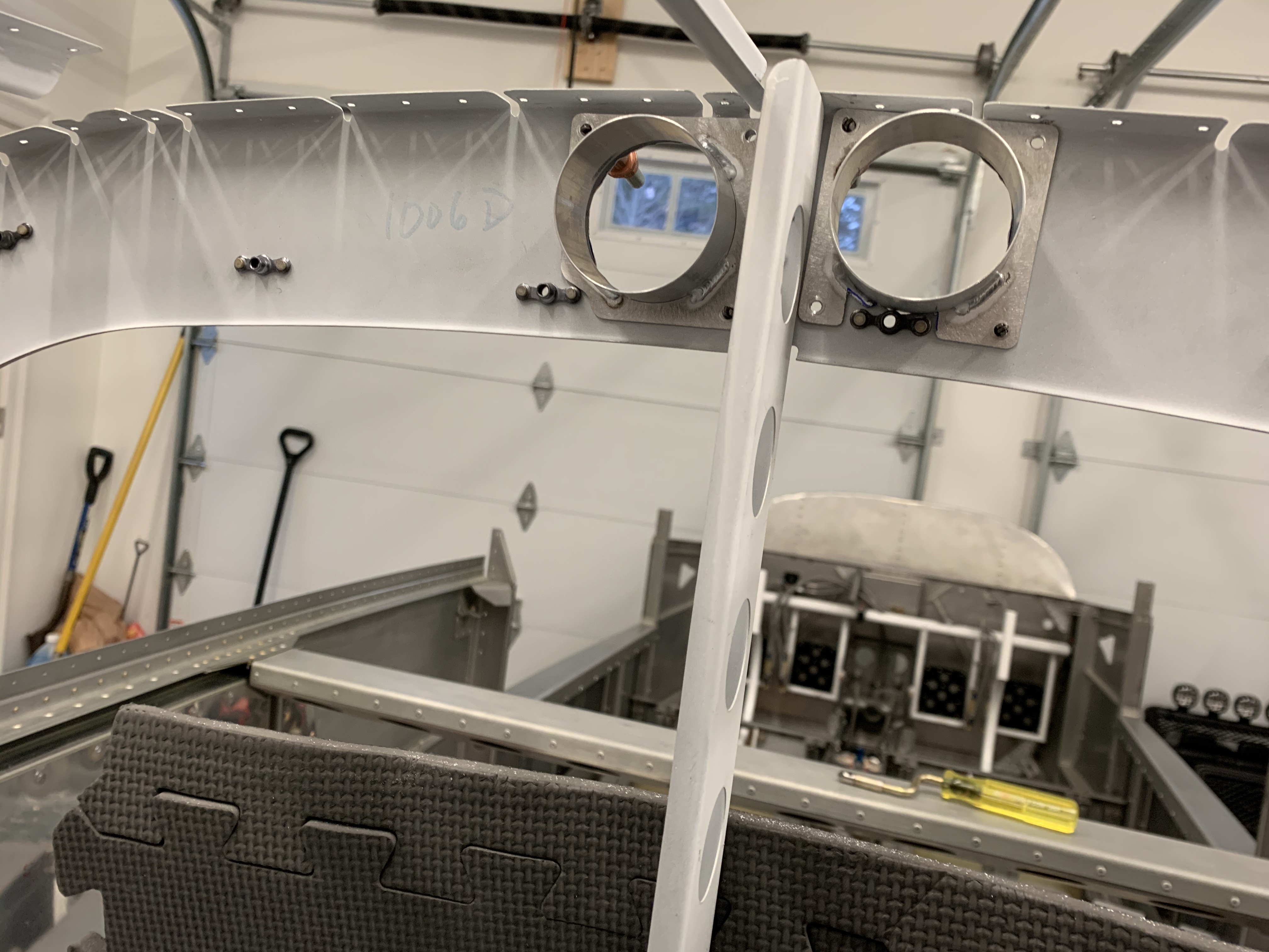
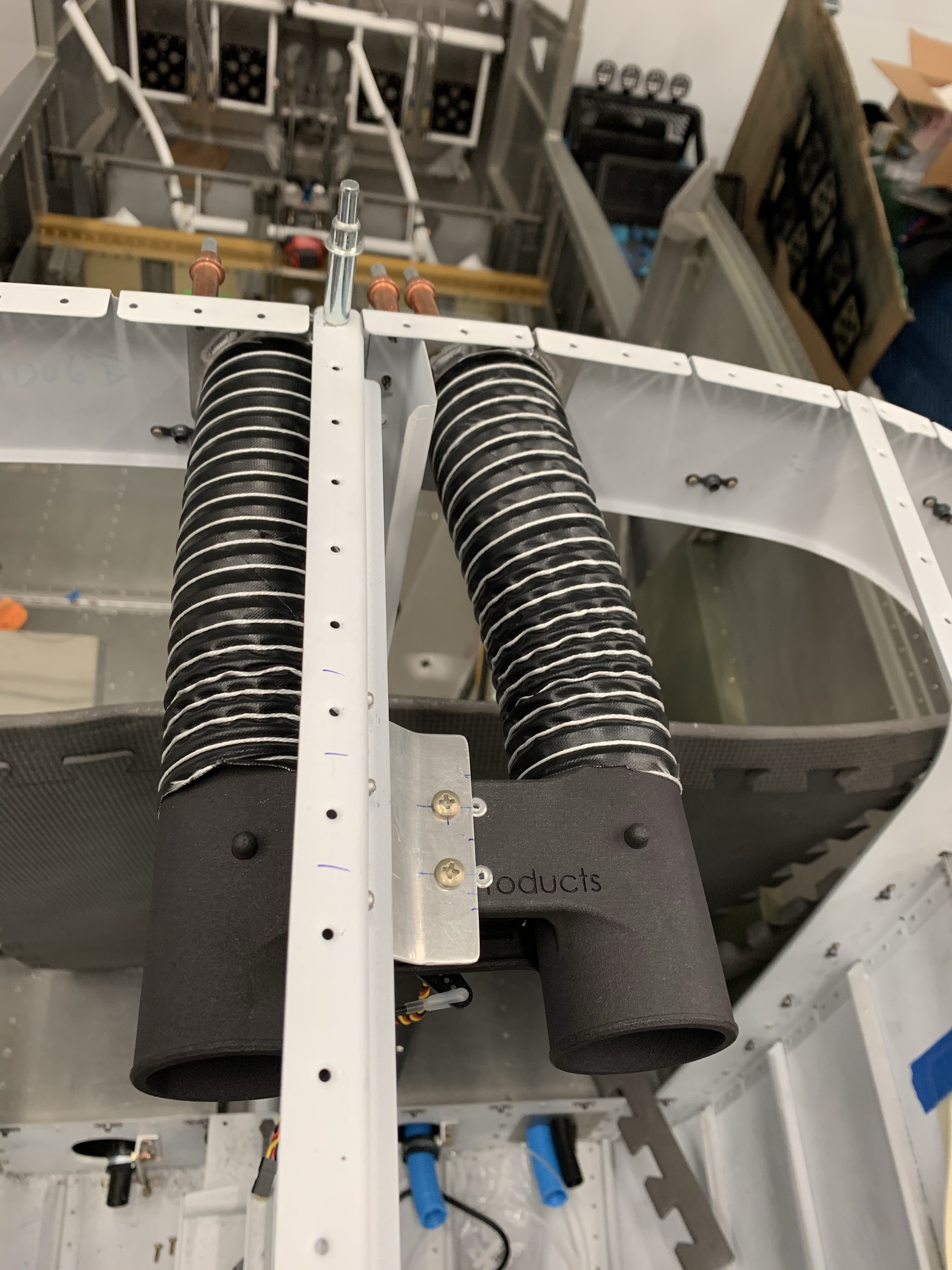
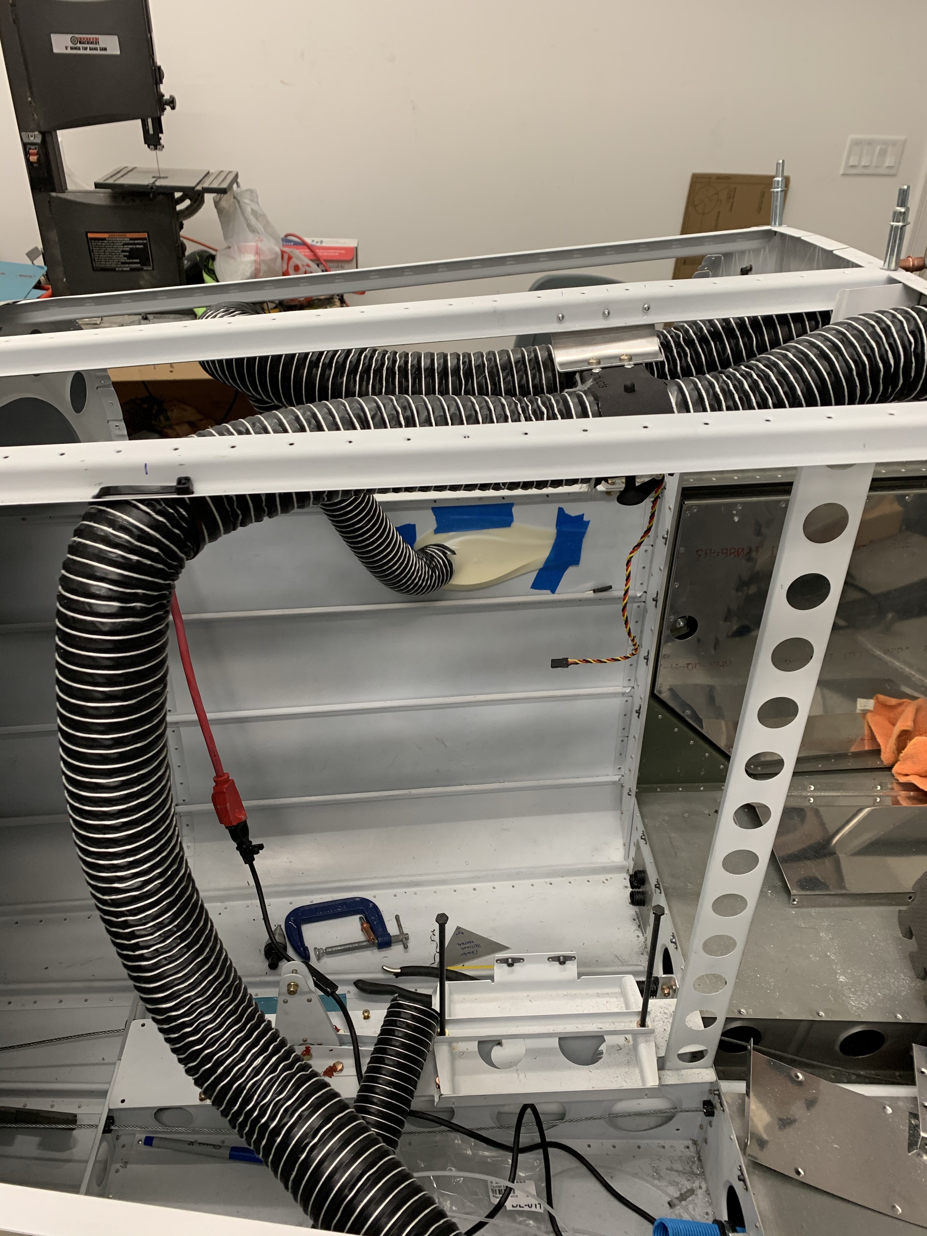
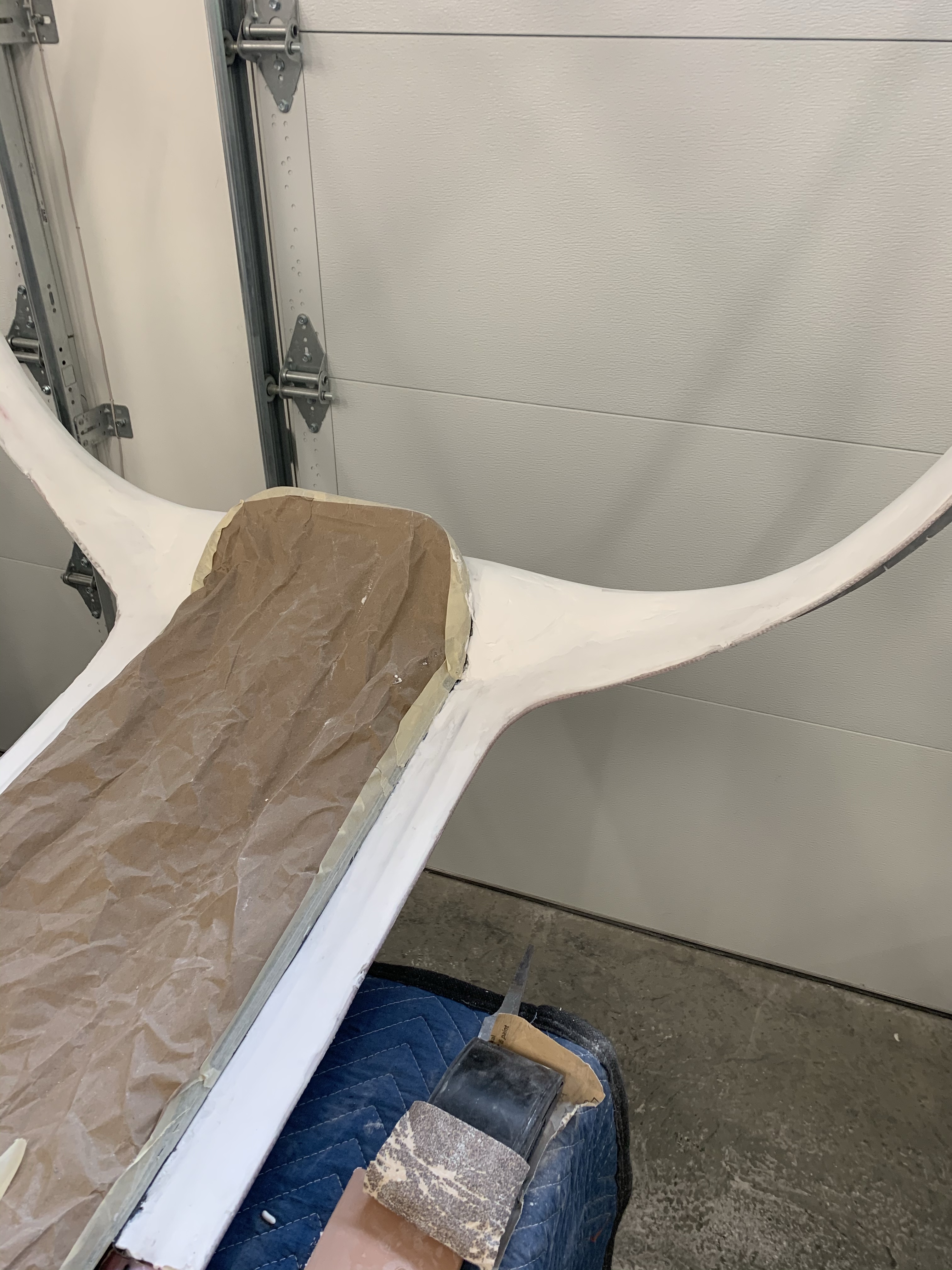
Continuing from last time, I shaped the foam build ups that house the conduits into the switch pod with a long knife and sandpaper. Here you can see the basic shape I was after. There were some imperfections, so in the end I put a layer of epoxy flox over this whole structure to harden it up and provide a good base for filler on top. I’m leaving a gap for the support bar to go into place and get bolted down. I’ll then glass over this front area later once the cabin top is attached to the plane and make it look nicer.

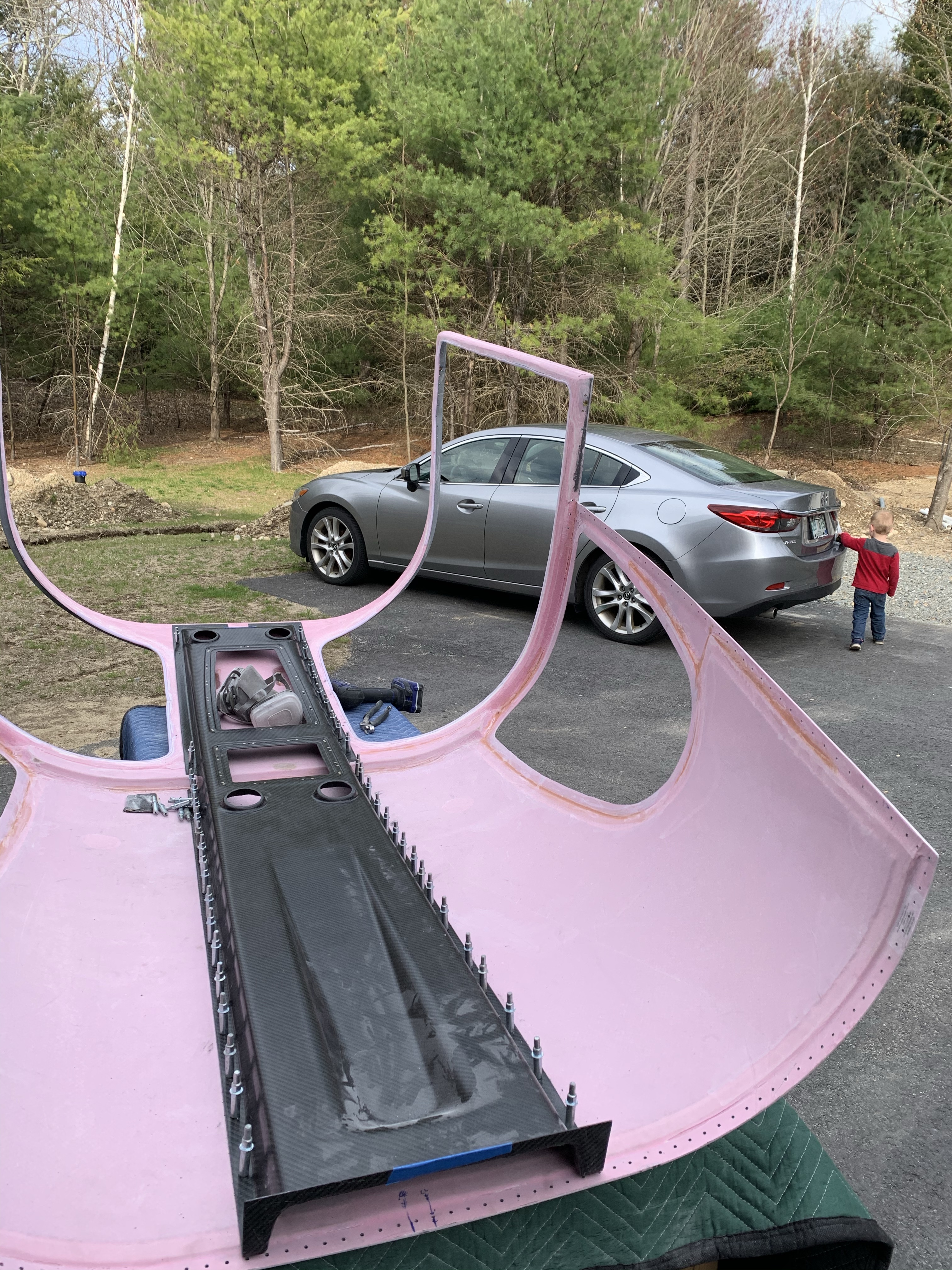
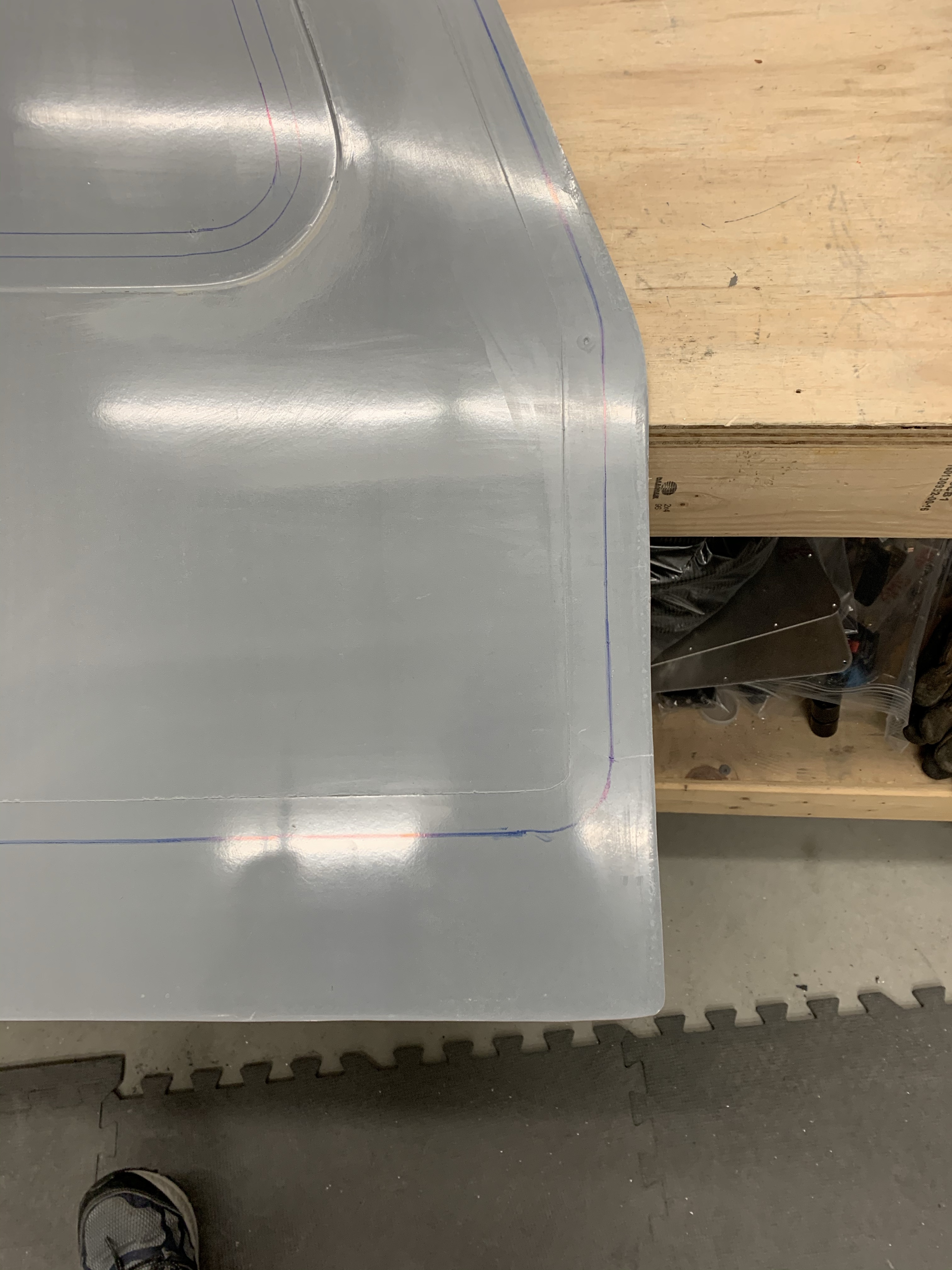
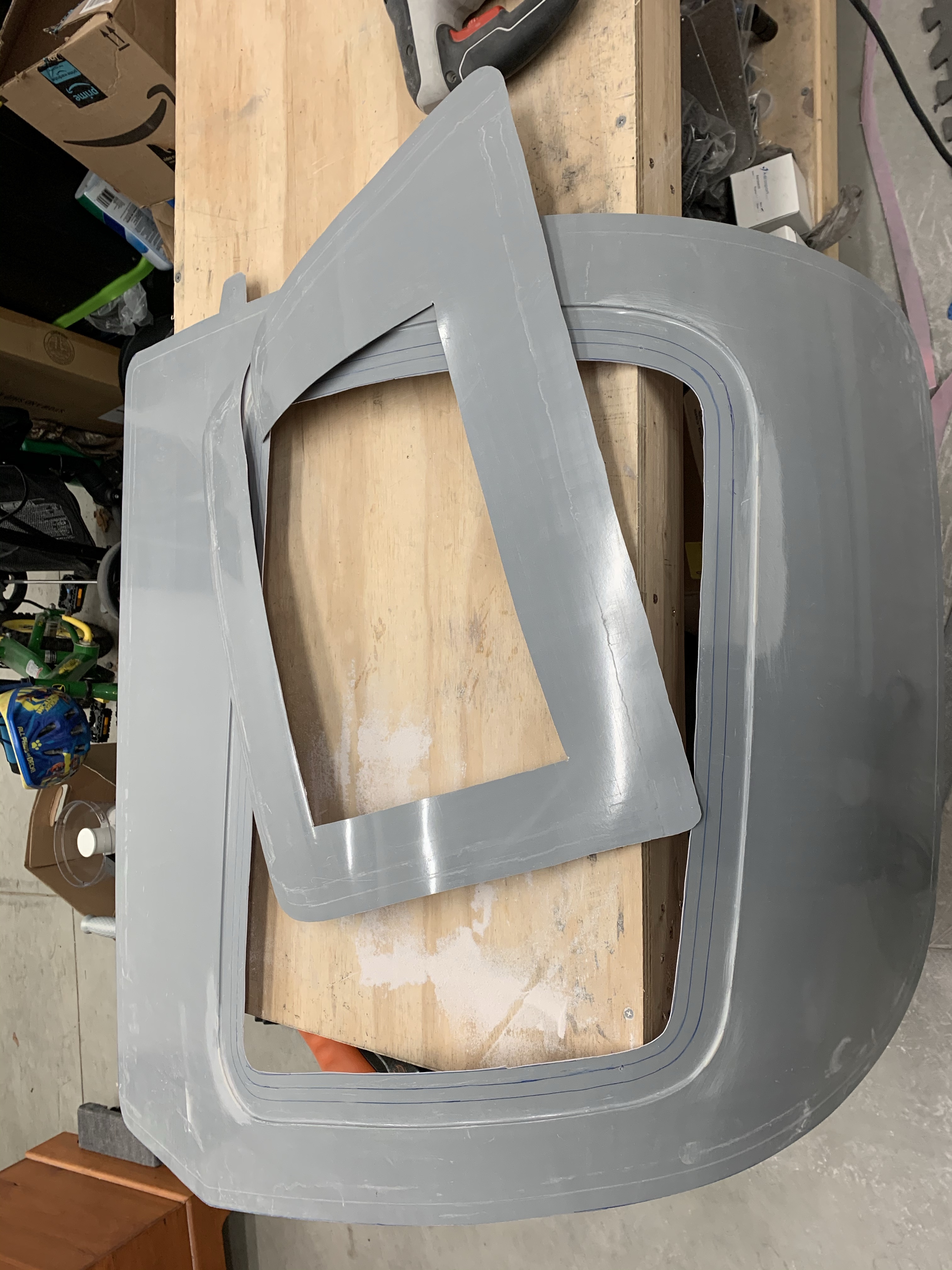
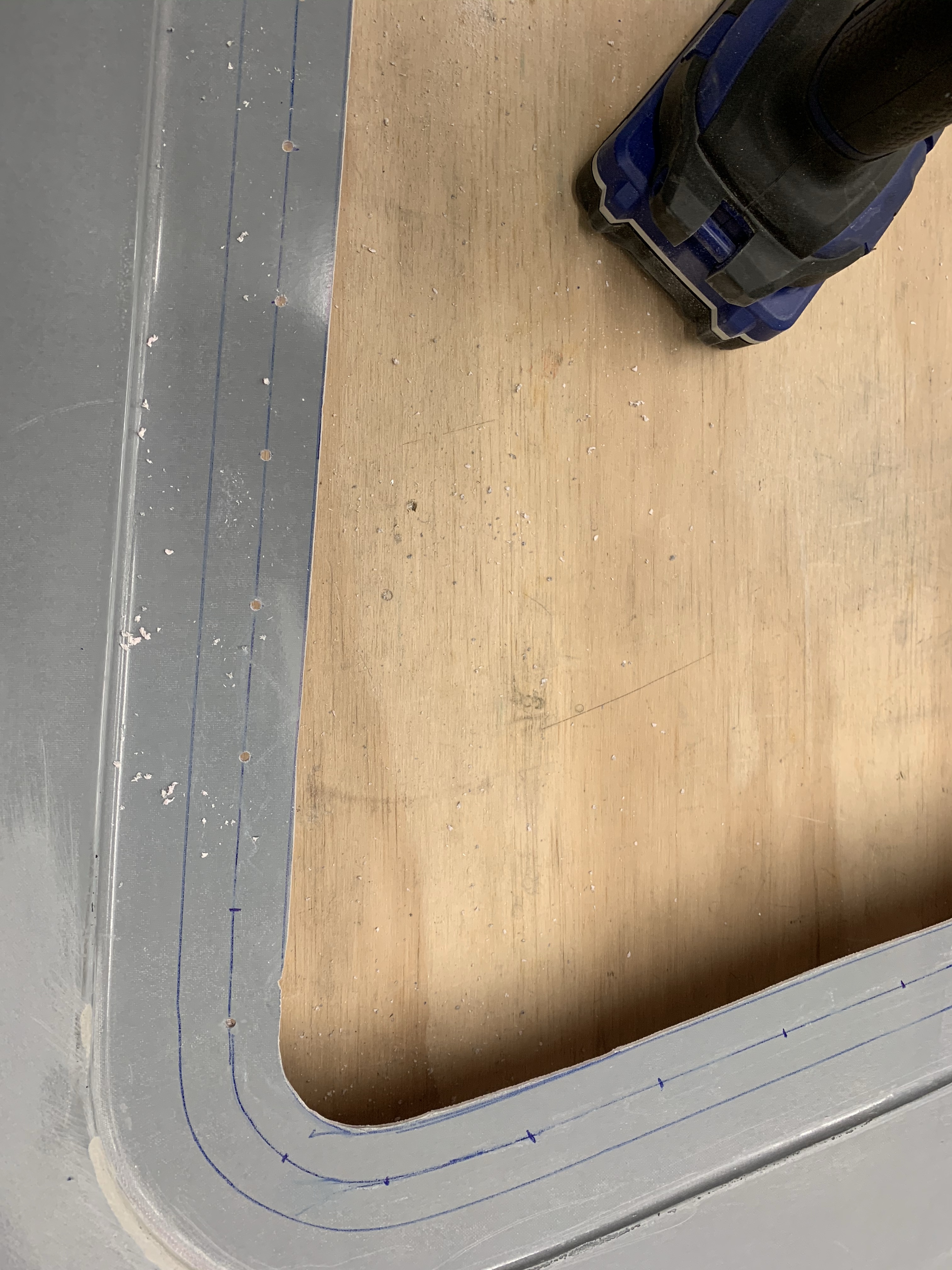
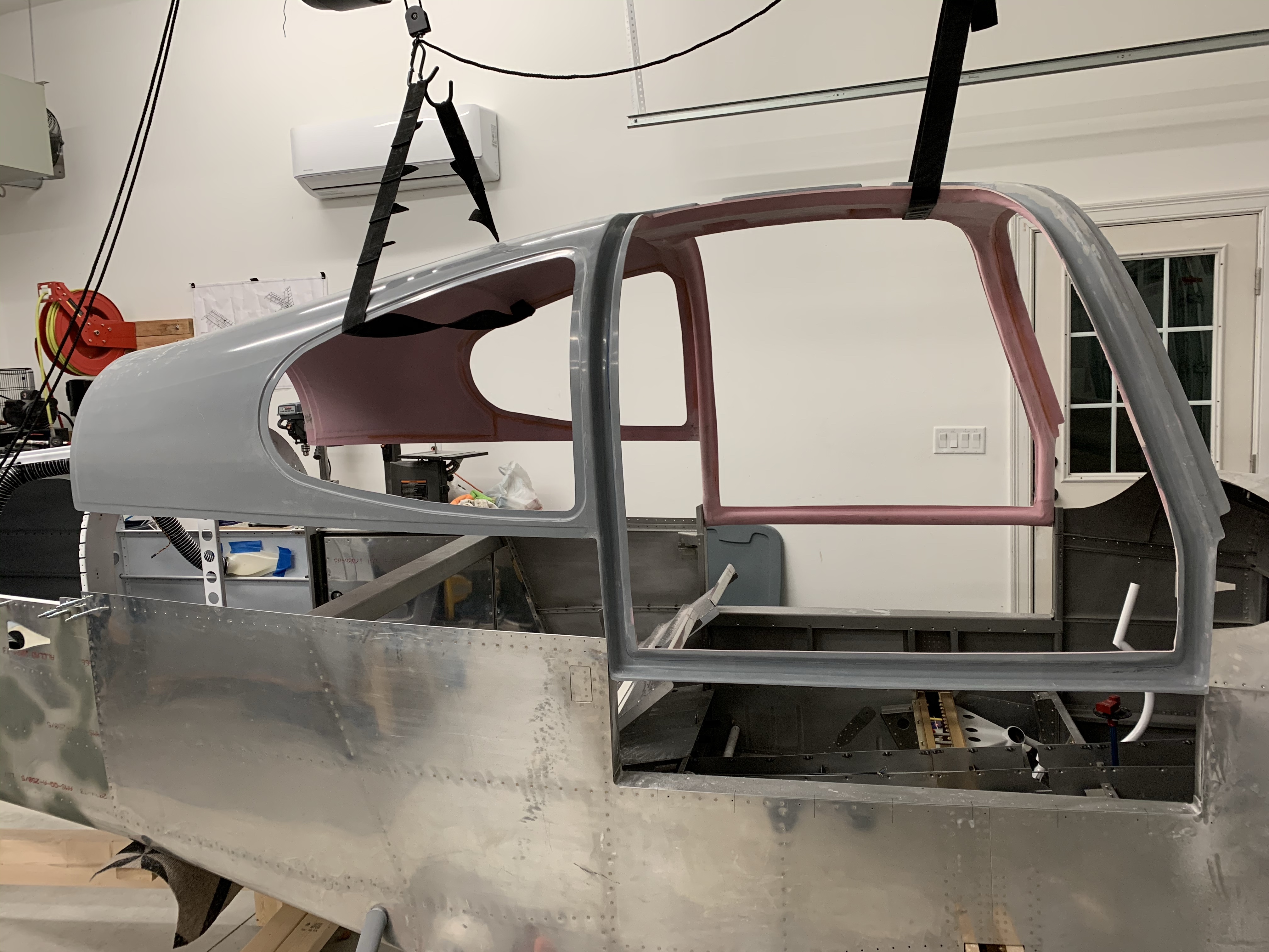
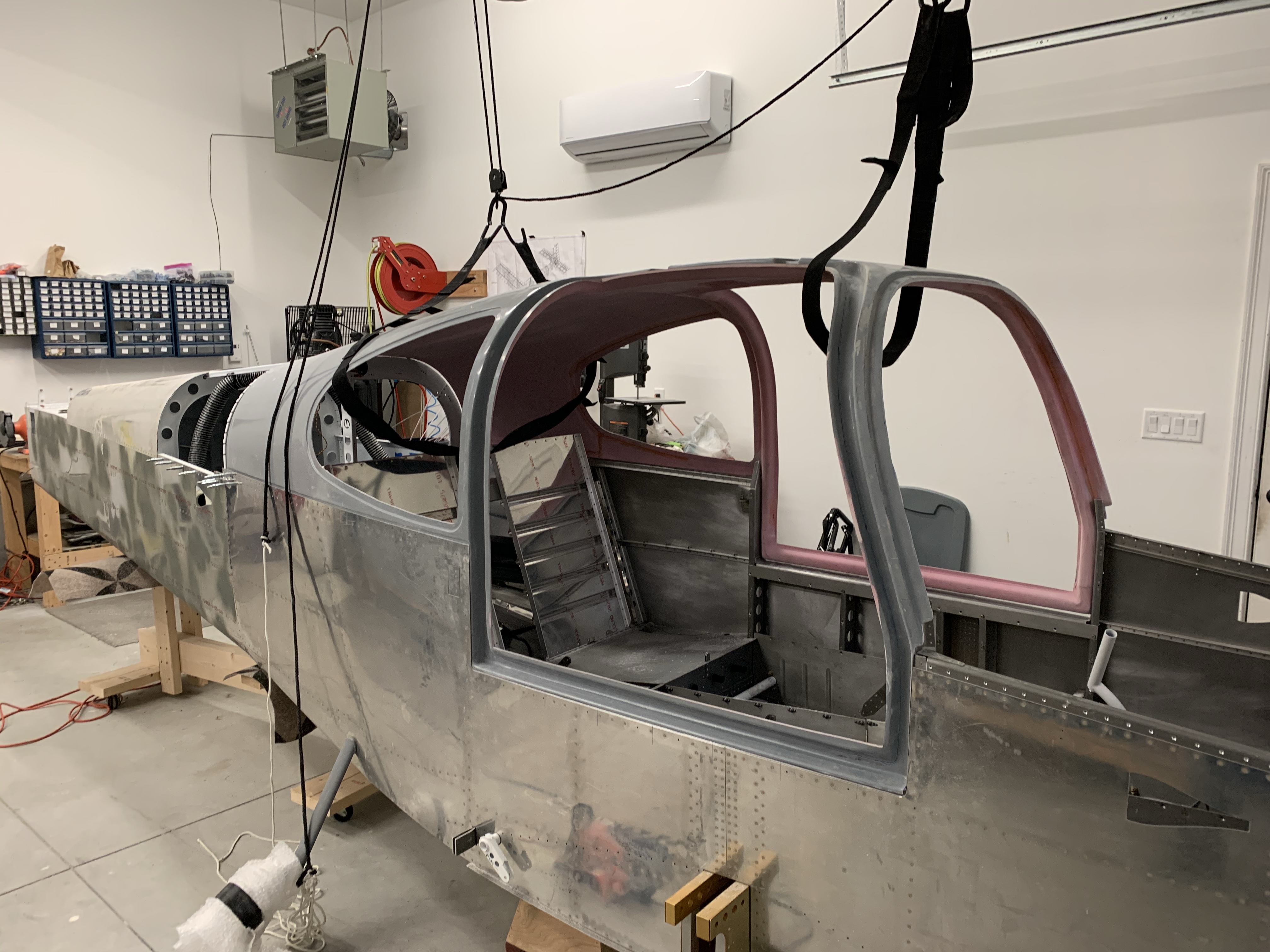
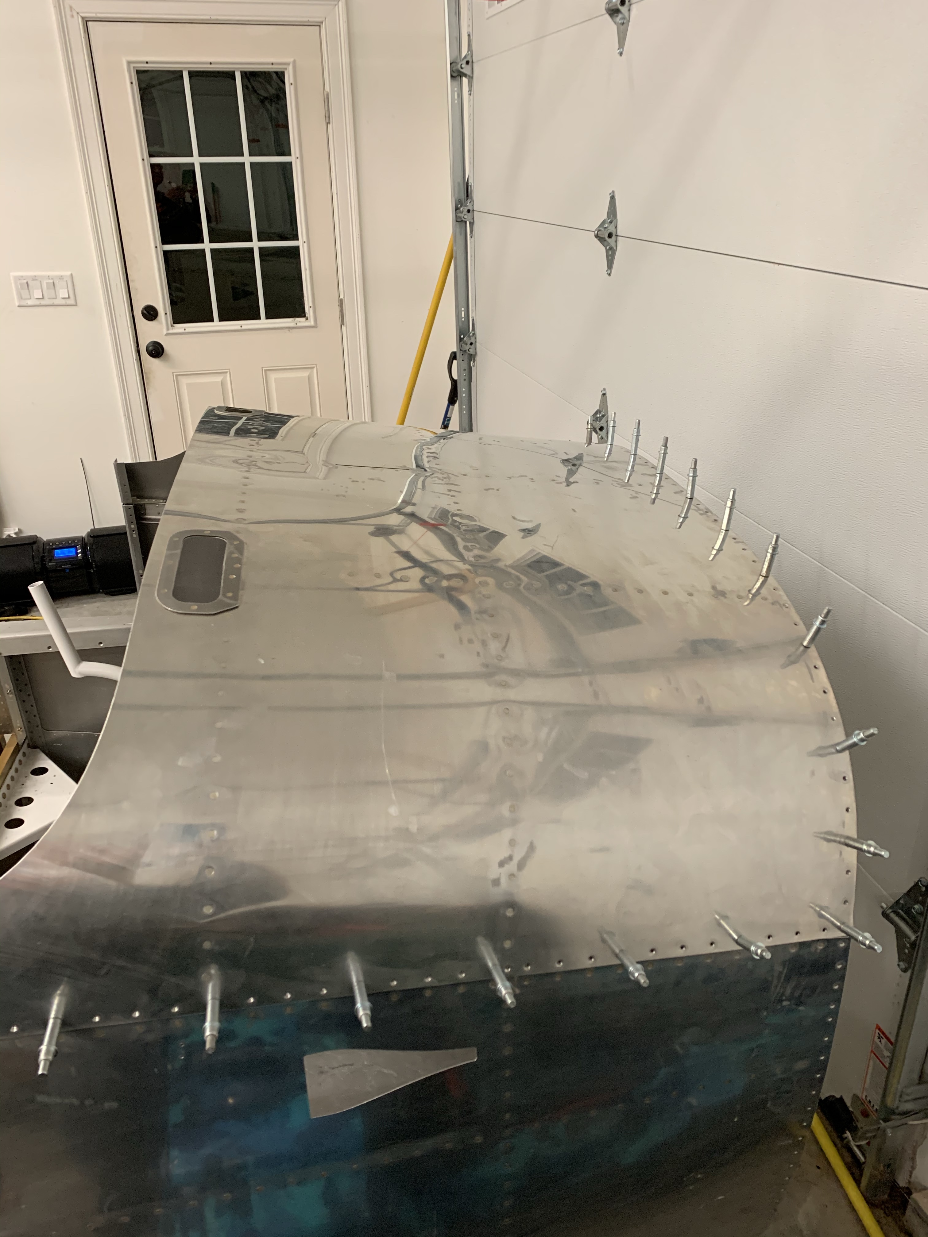
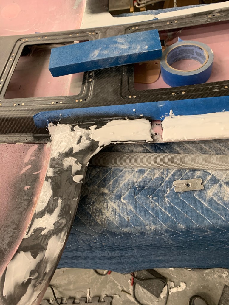
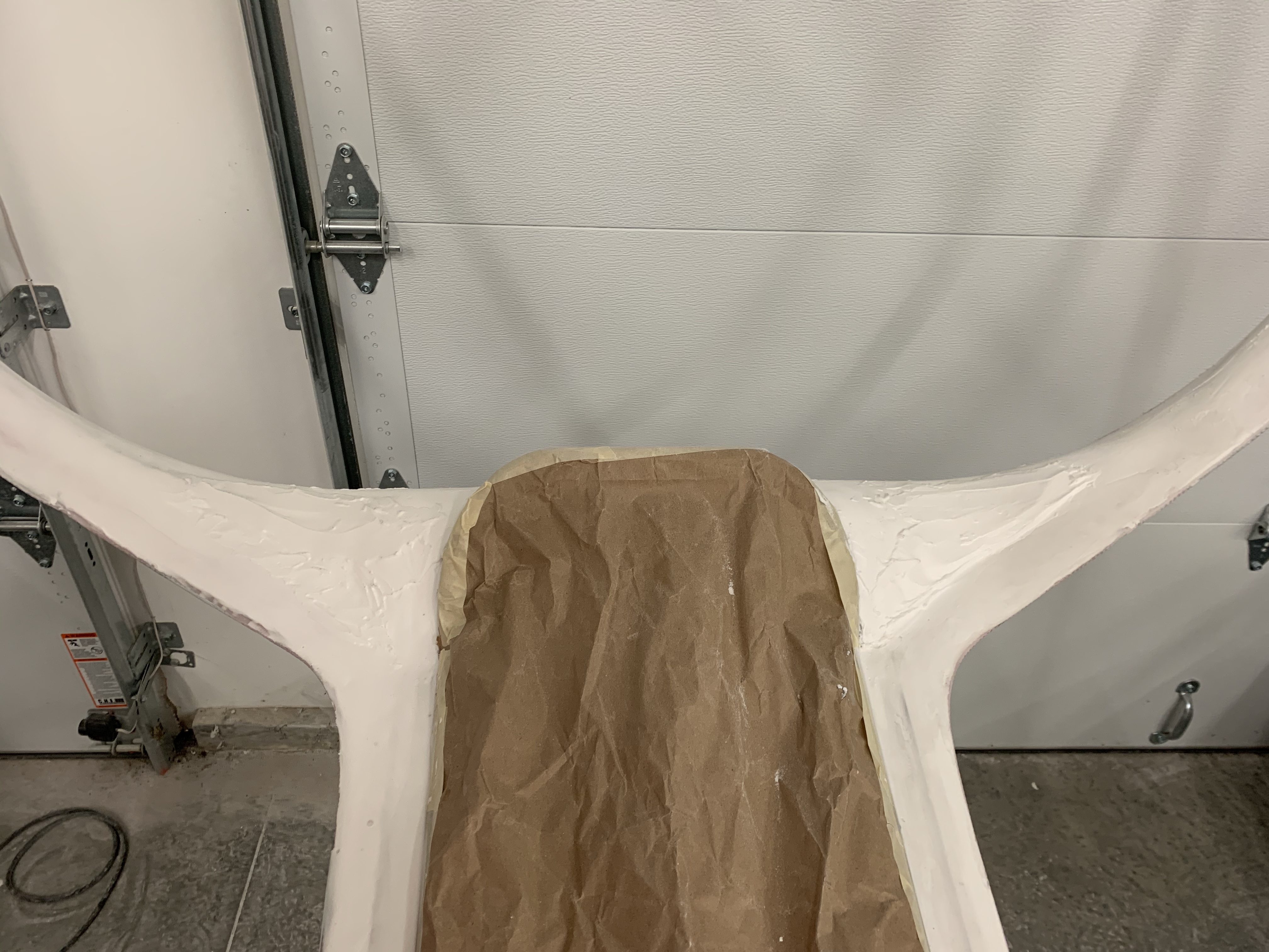
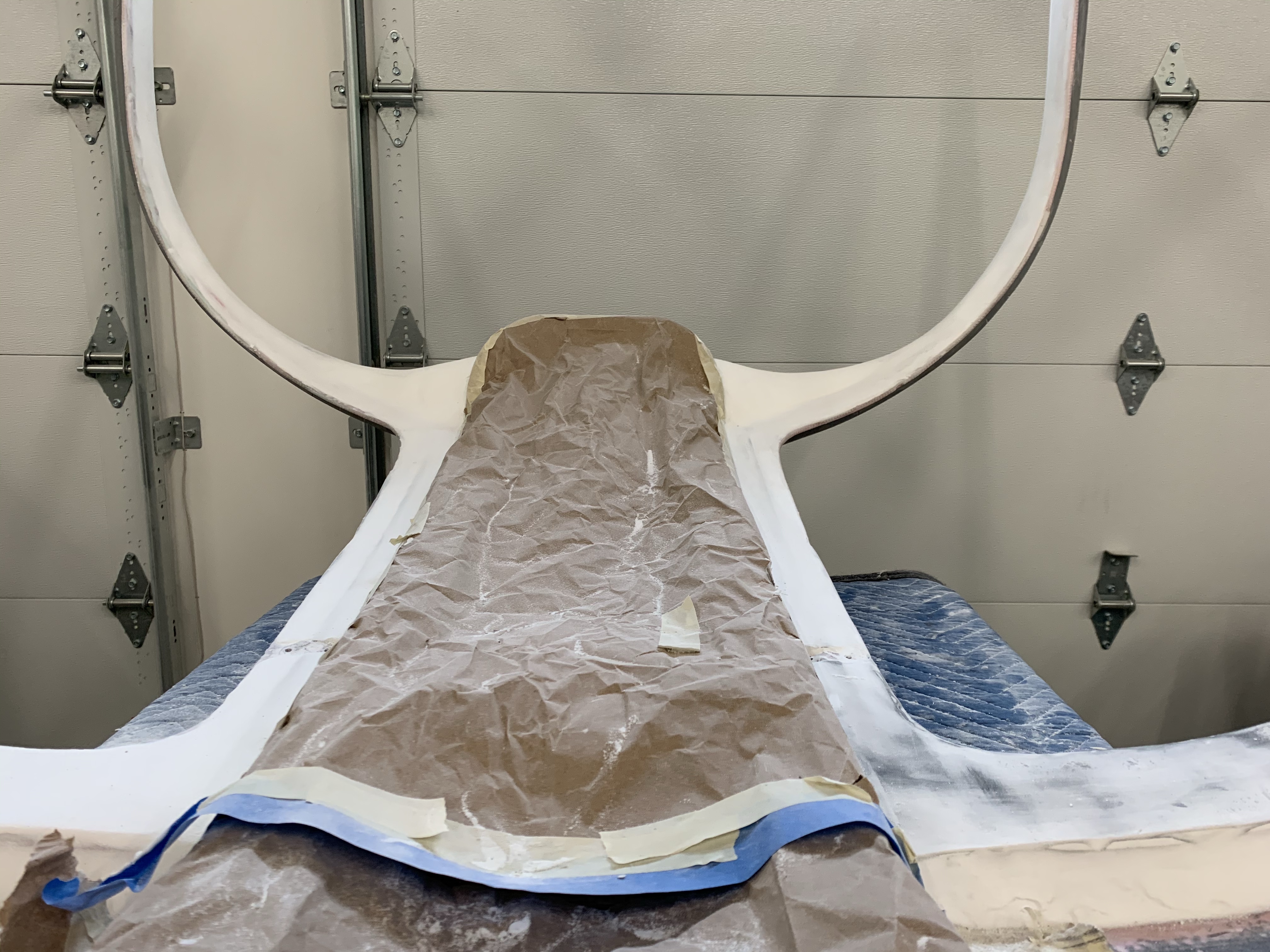
Then it was time to start filling in the surfaces that will be exposed and painted with filler. Initially I chose to use a polyester bondo material called Evercoat Rage Ultra. I did the vast majority of the right side with this.. I wasn’t really happy with it in the end. I found it difficult to mix properly and it did really stink the garage up really badly. I then tried using the more generally accepted epoxy and microballons as a filler on the left side. This seemed to go much better. I felt like I could mix it up properly and fairly consistently each time and it was easier to spread. I also doesn’t smell at all.. I’m sure most of my struggle with the bondo was inexperience and sticking with it probably would have gotten better, but I decided to forge ahead just using the micro. I spent the better part of 2-3 hours sanding off the bondo that I had put on the right side until I was down to pink again.. . I then spent several sessions of filling and sanding.. filling and sanding the micro over all the exposed areas. Through this process, I learned that it’s ideal to mix up enough for the whole job and spread more than you’ll need rather than doing multiple fill and sand sessions. The thought here is that you’ll never mix the epoxy and micro to the same ratio between batches and the 2 different mixtures have different densities making it hard to sand well. So far I haven’t found it to be too much of a problem, but I’ve also not painted it yet.. so maybe time will tell. The below pictures are various stages of slathering on micro around the door pillars and flat areas in the door entries.
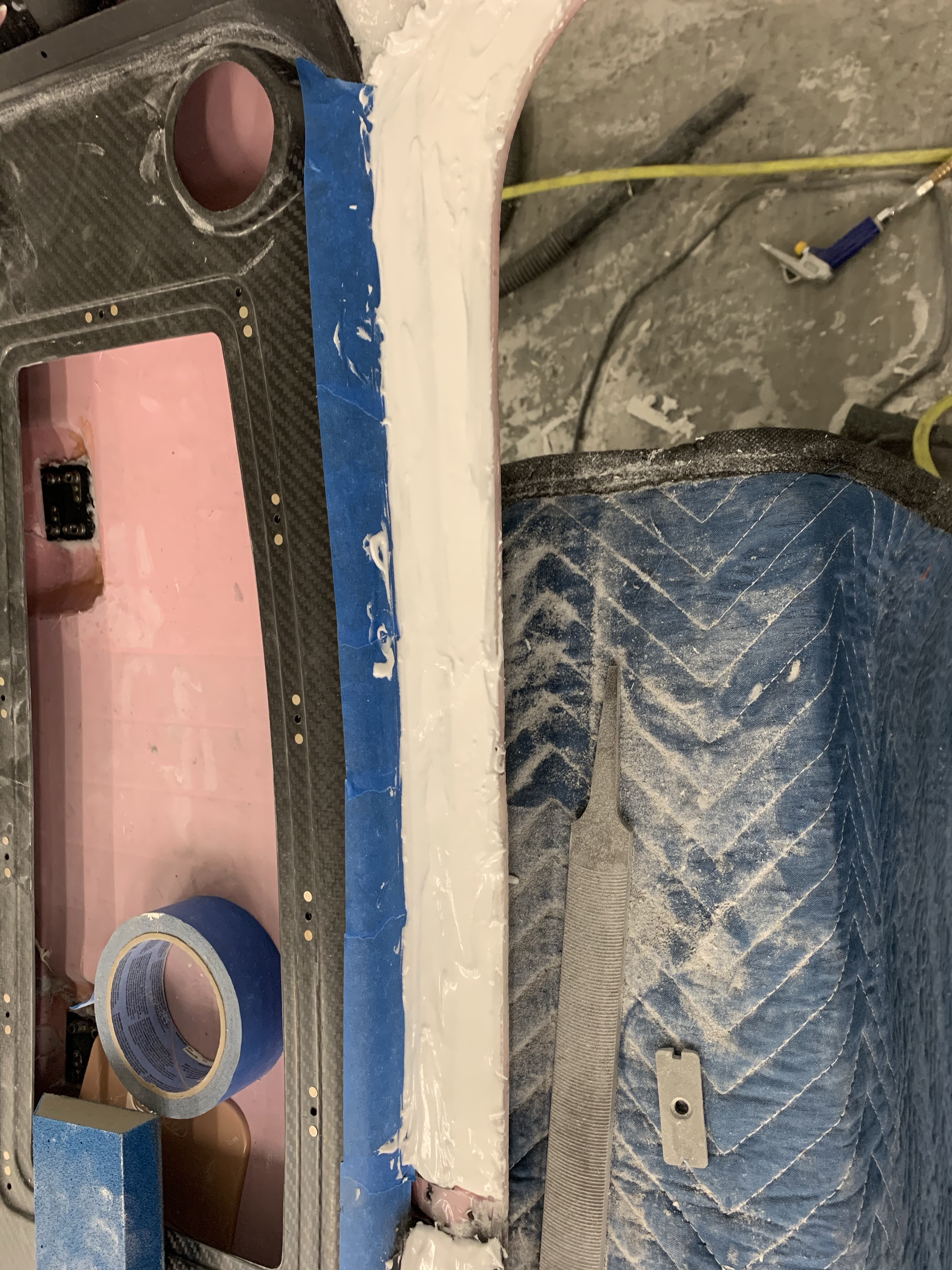
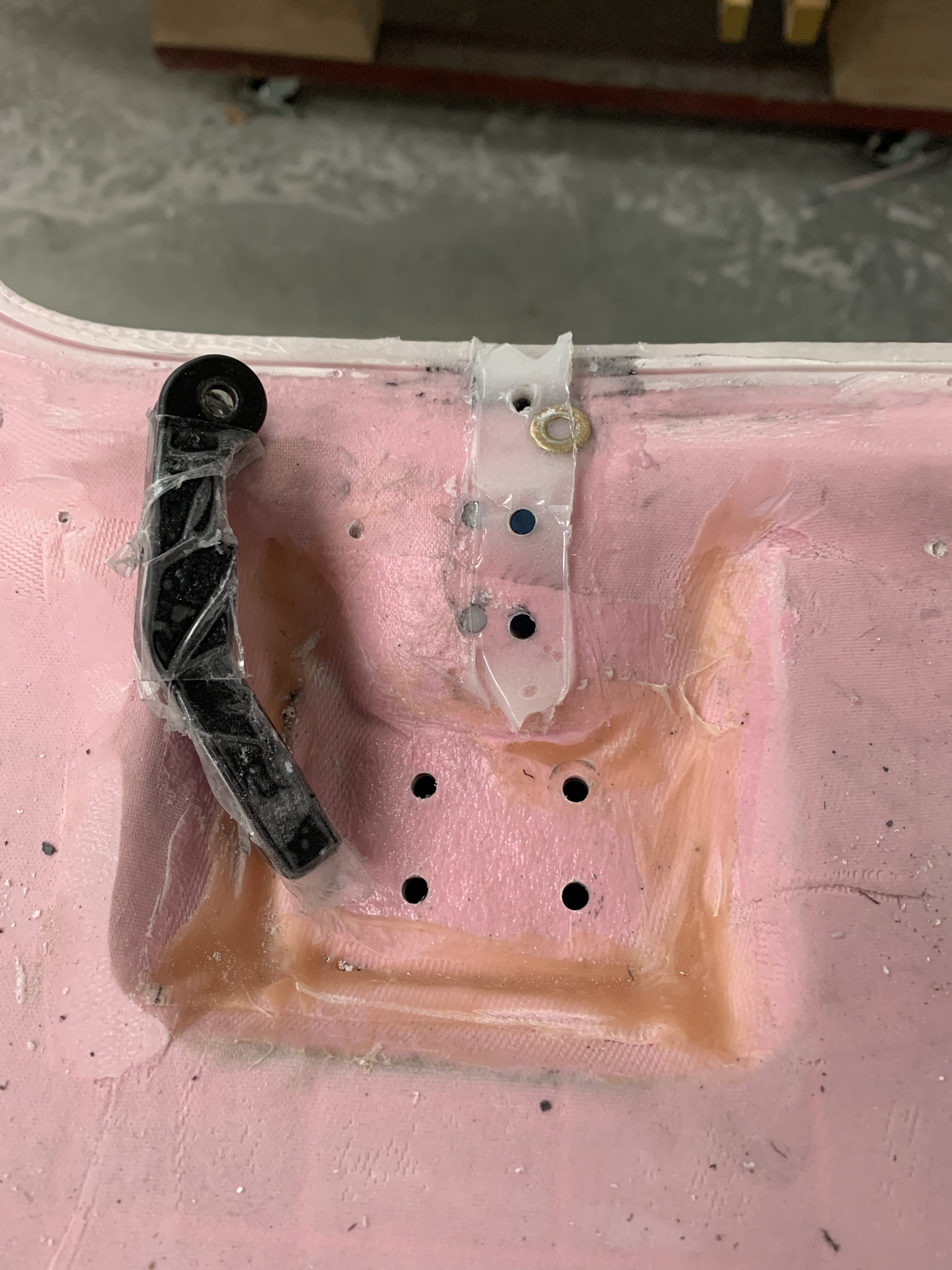
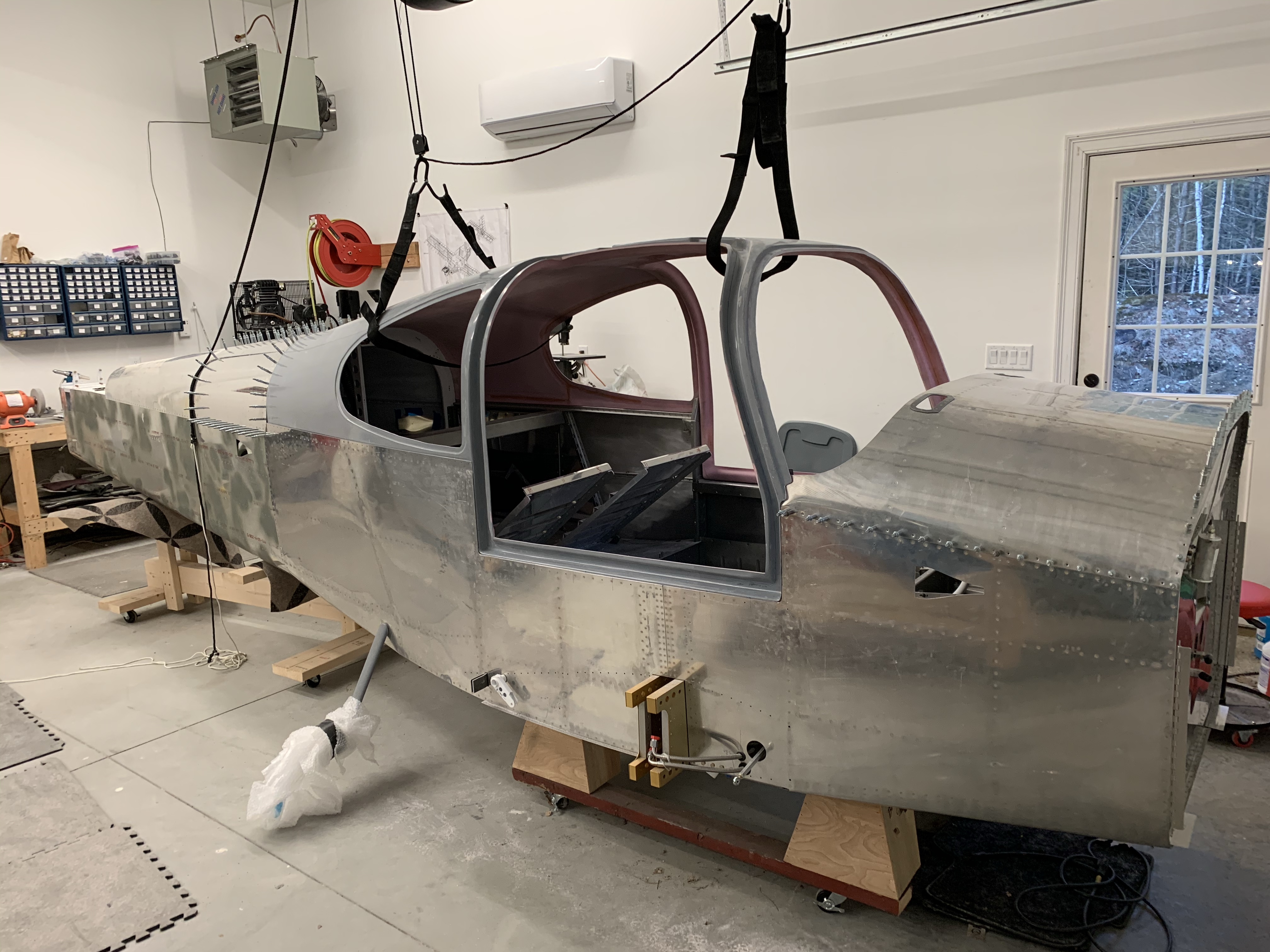
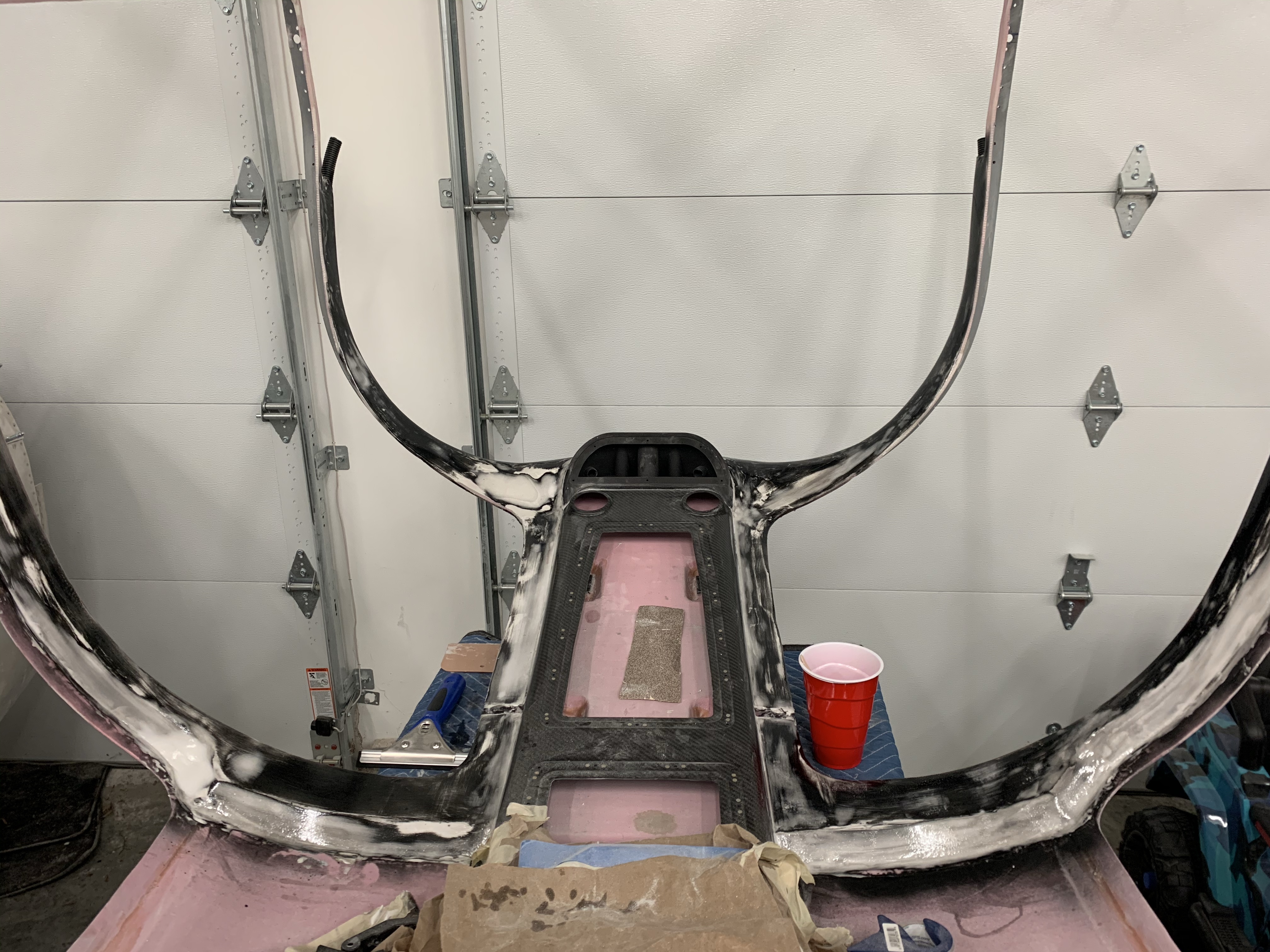
You’ll see below that I did end up spraying some black primer that I had lying around as sort of a guide coat prior to adding more micro. This can help see low spots easier as well as help as a sanding aide to not sand deeper than before. If you see black start coming through, you know to stop. In the end, I don’t think this was really needed.. I think judging with your eyes and fingers do just as good of a job in the right light.
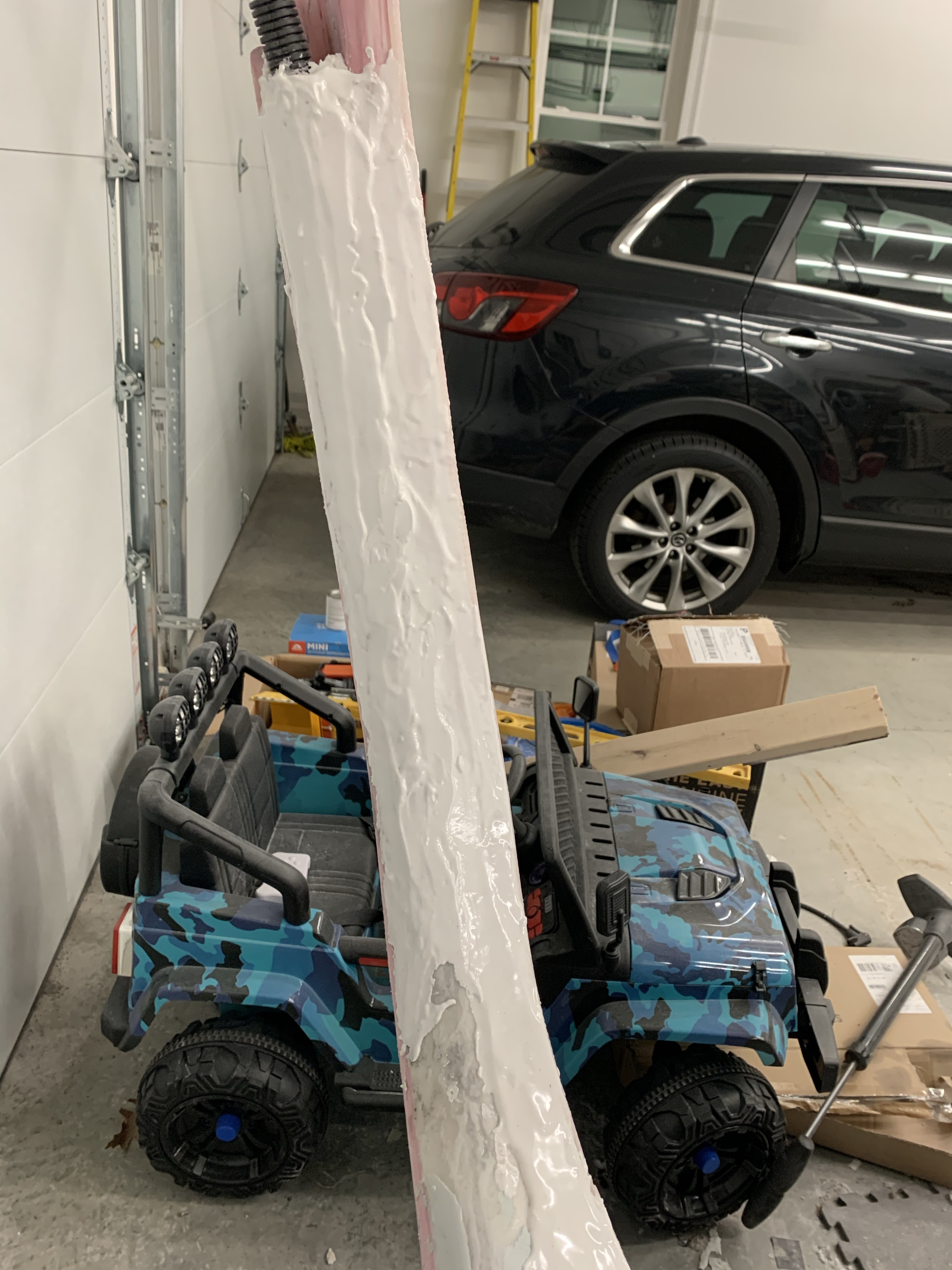


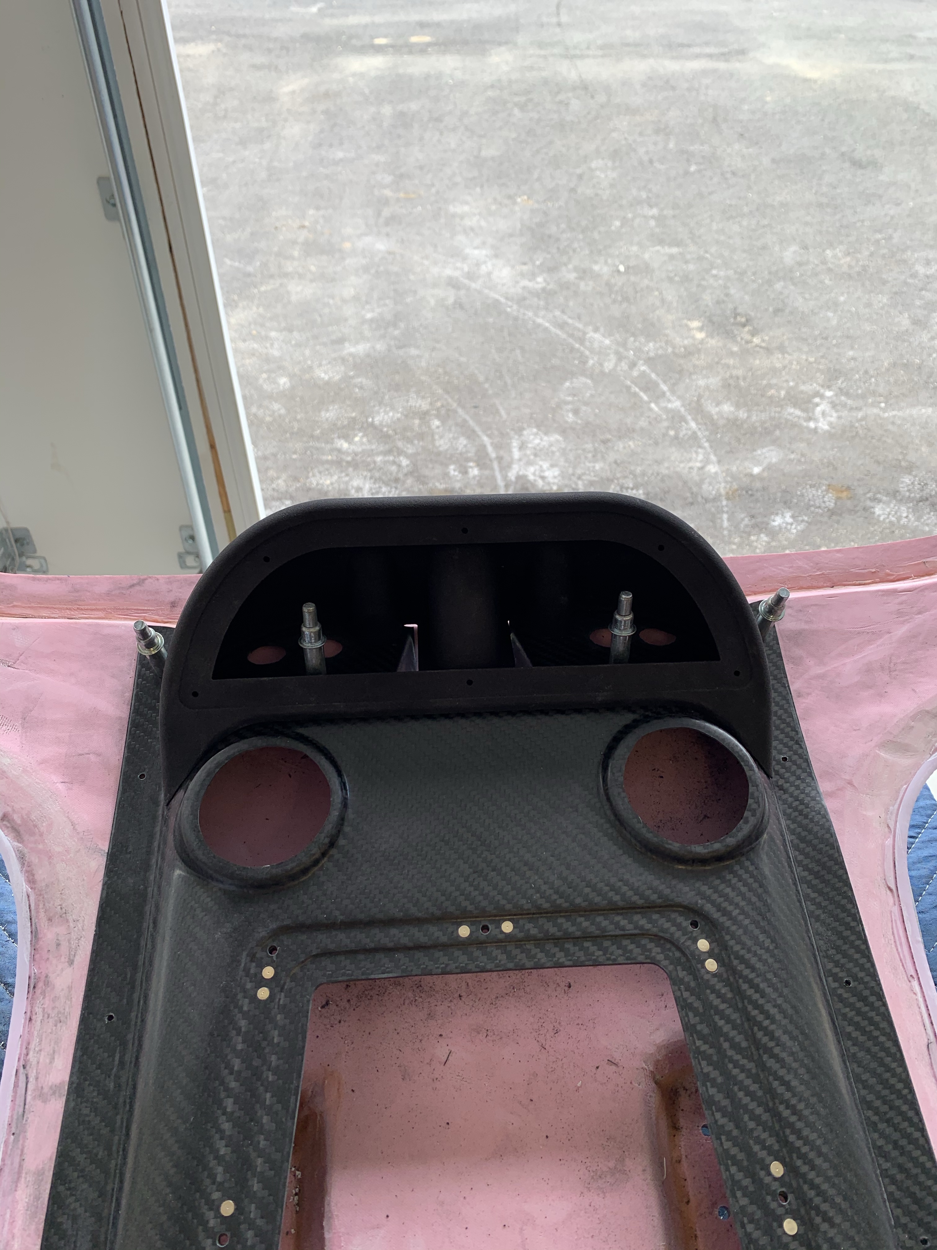
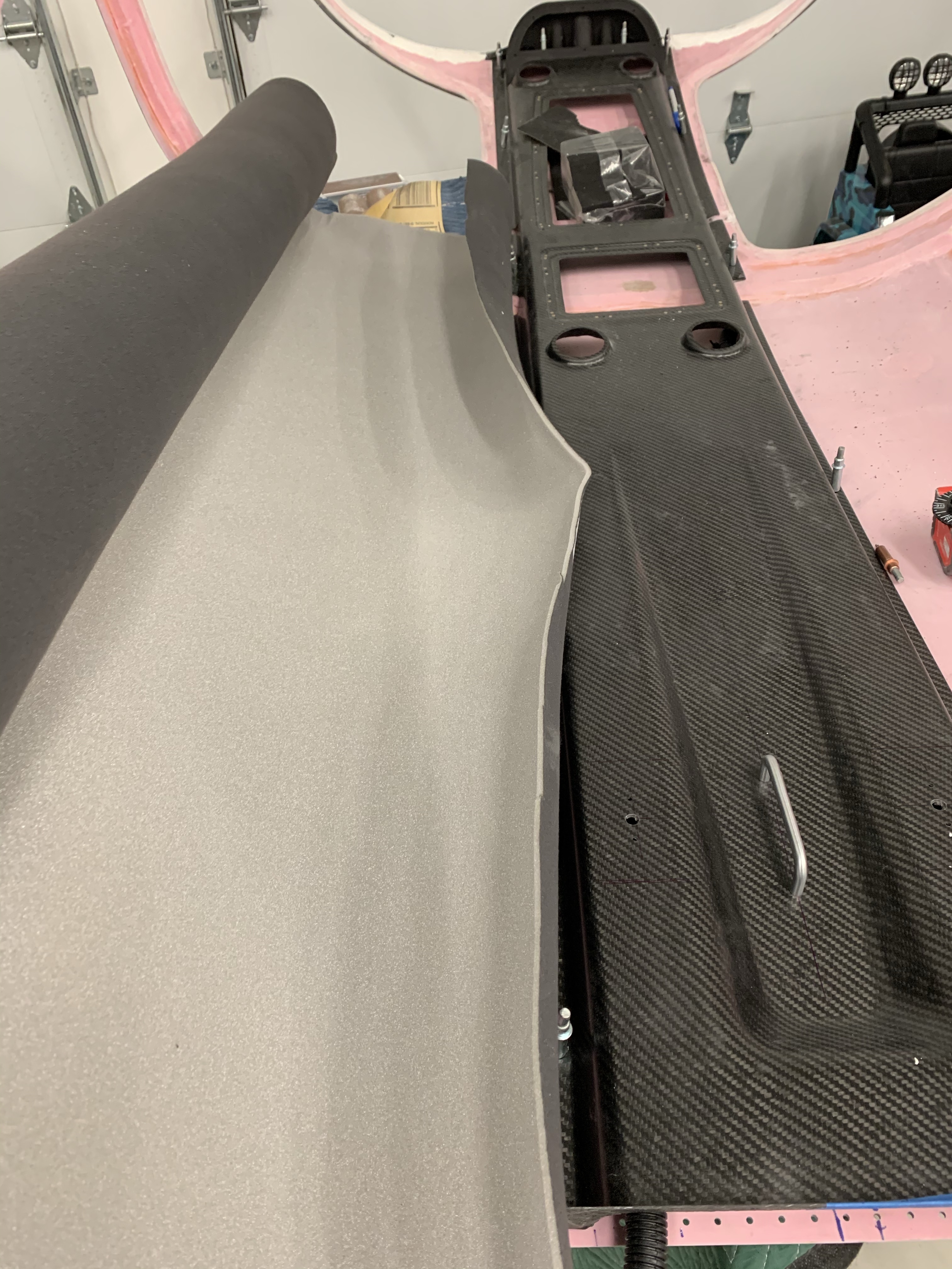
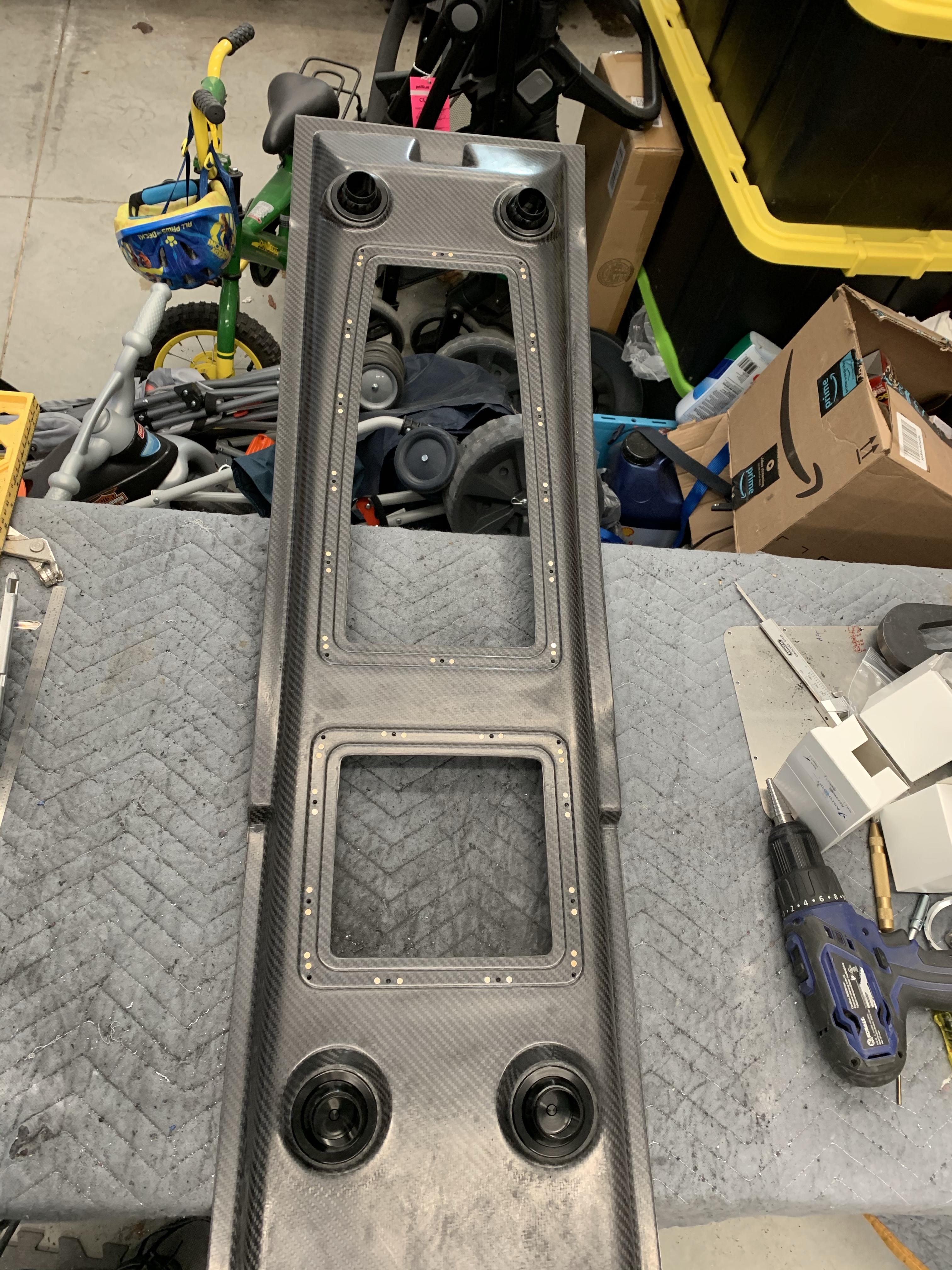
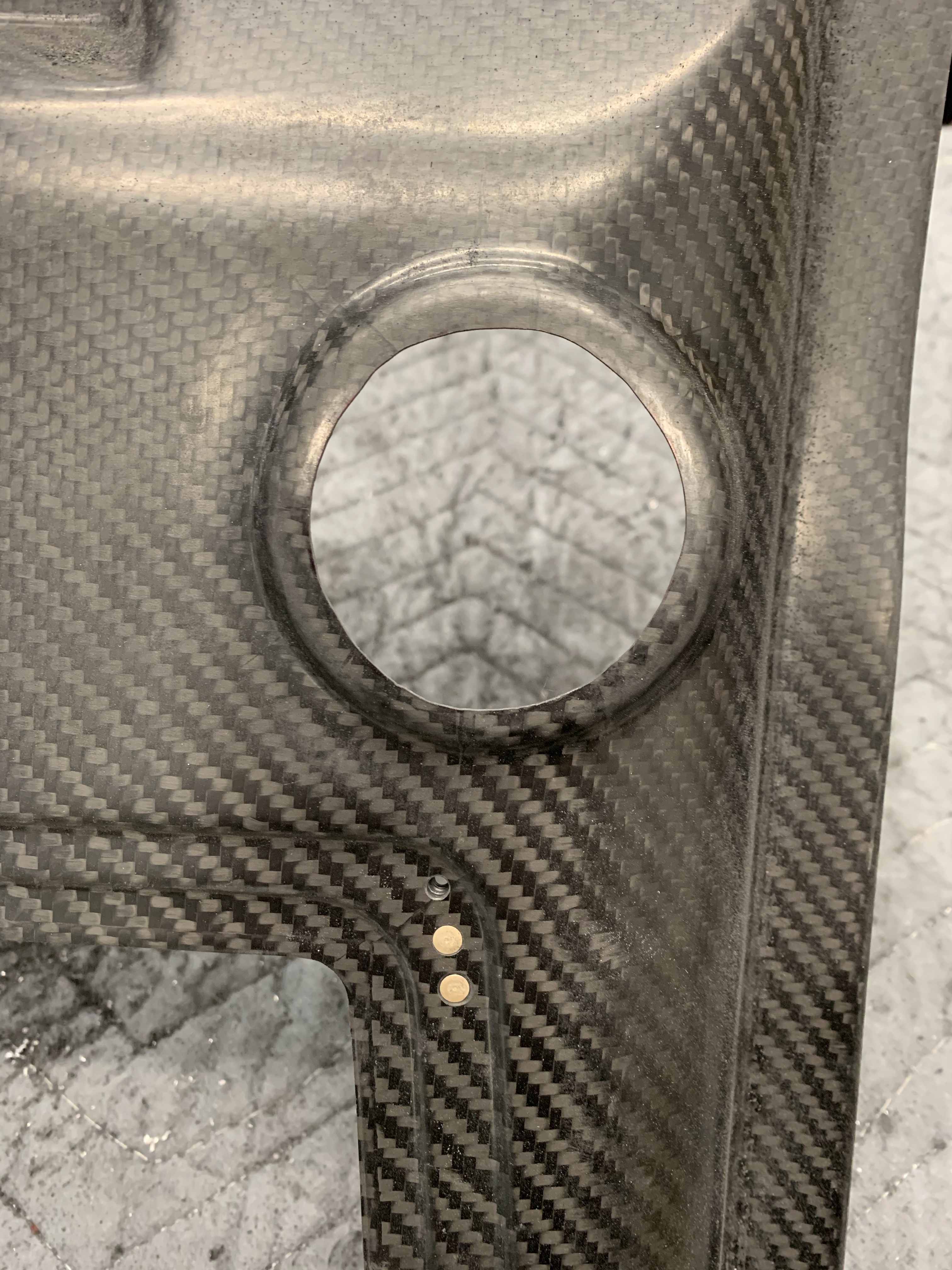
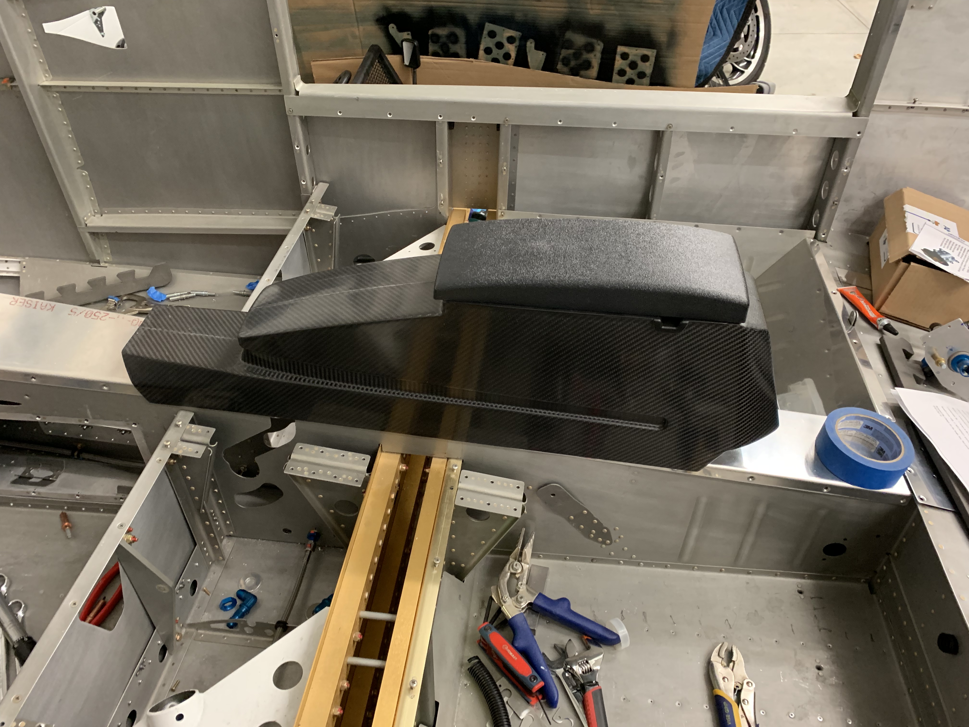
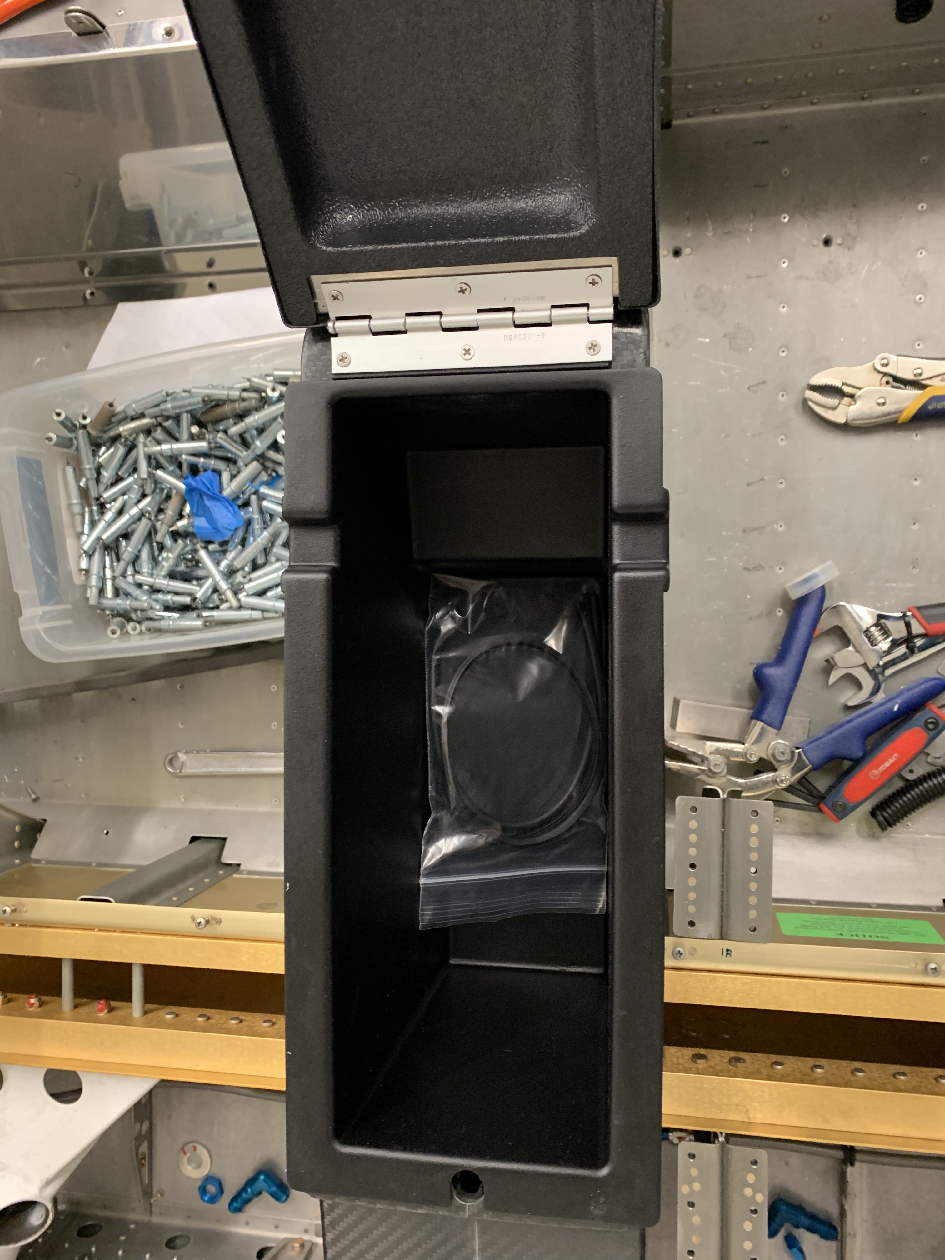
The below pictures show a better profile of the build up into the switch pod. Here it’s still not perfect yet as I needed to fill imperfections and blend into the flat part a bit better.


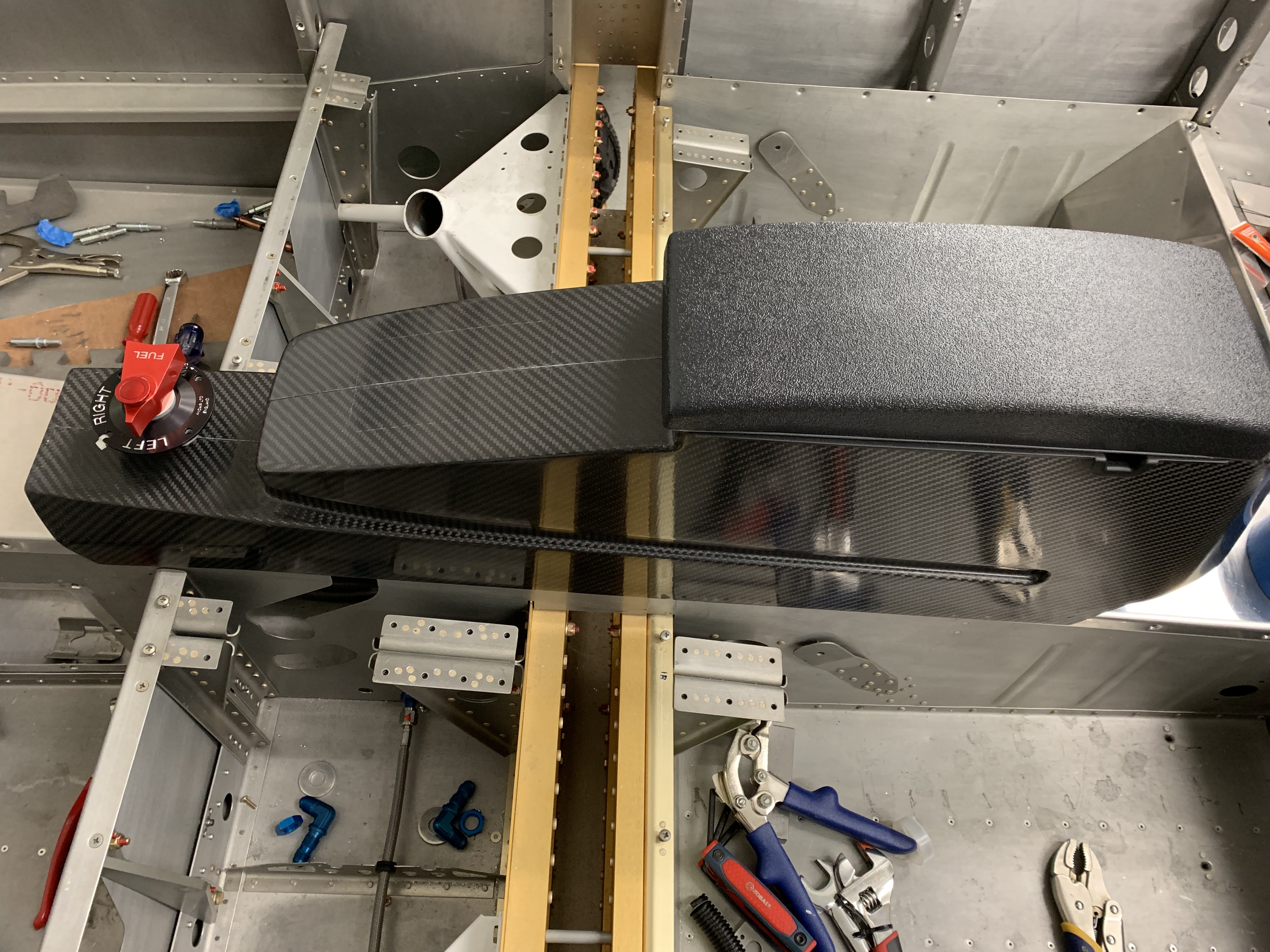
Here I’m just about at the point of being happy with the overall shape and have little to no imperfections.

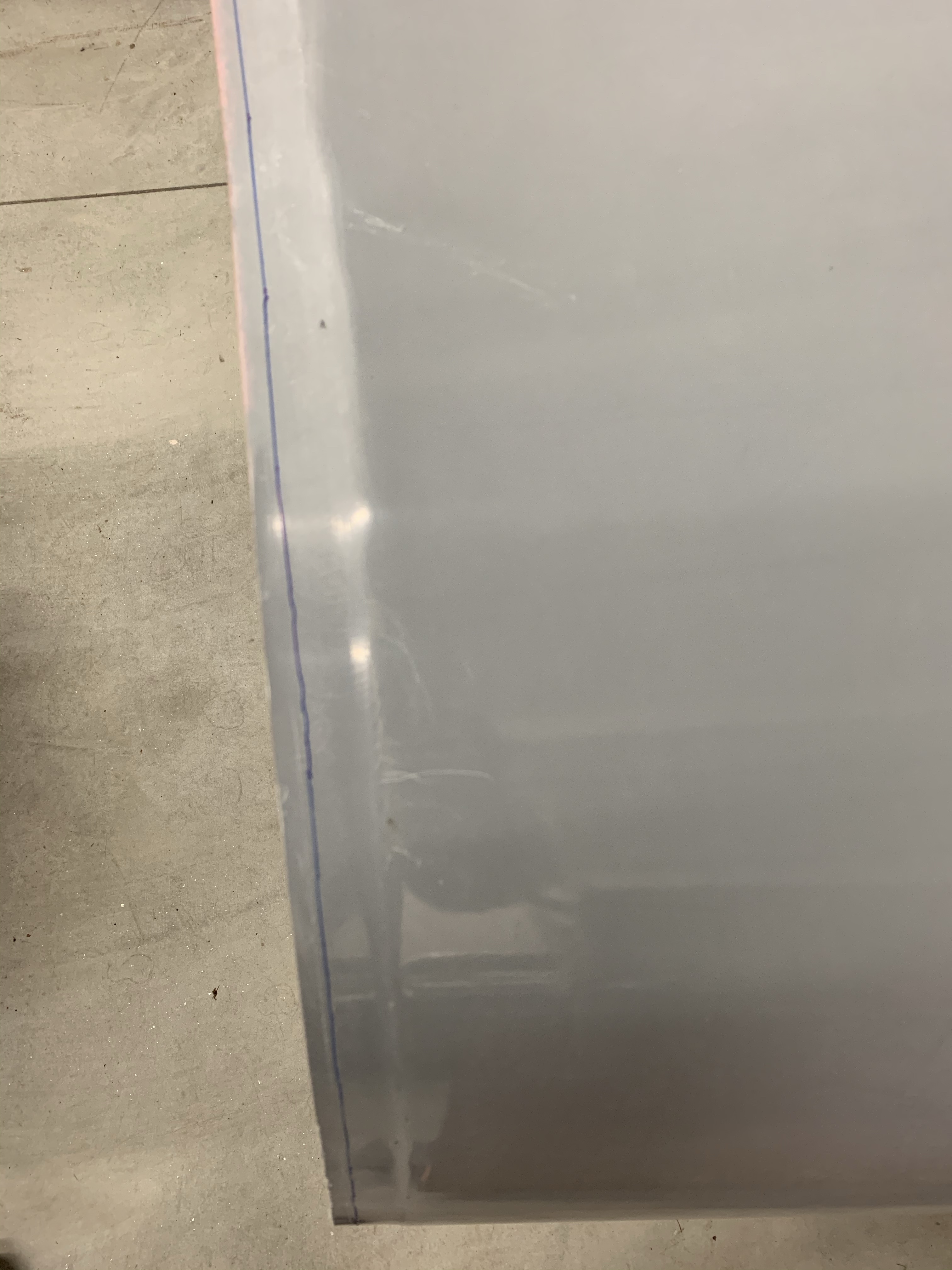
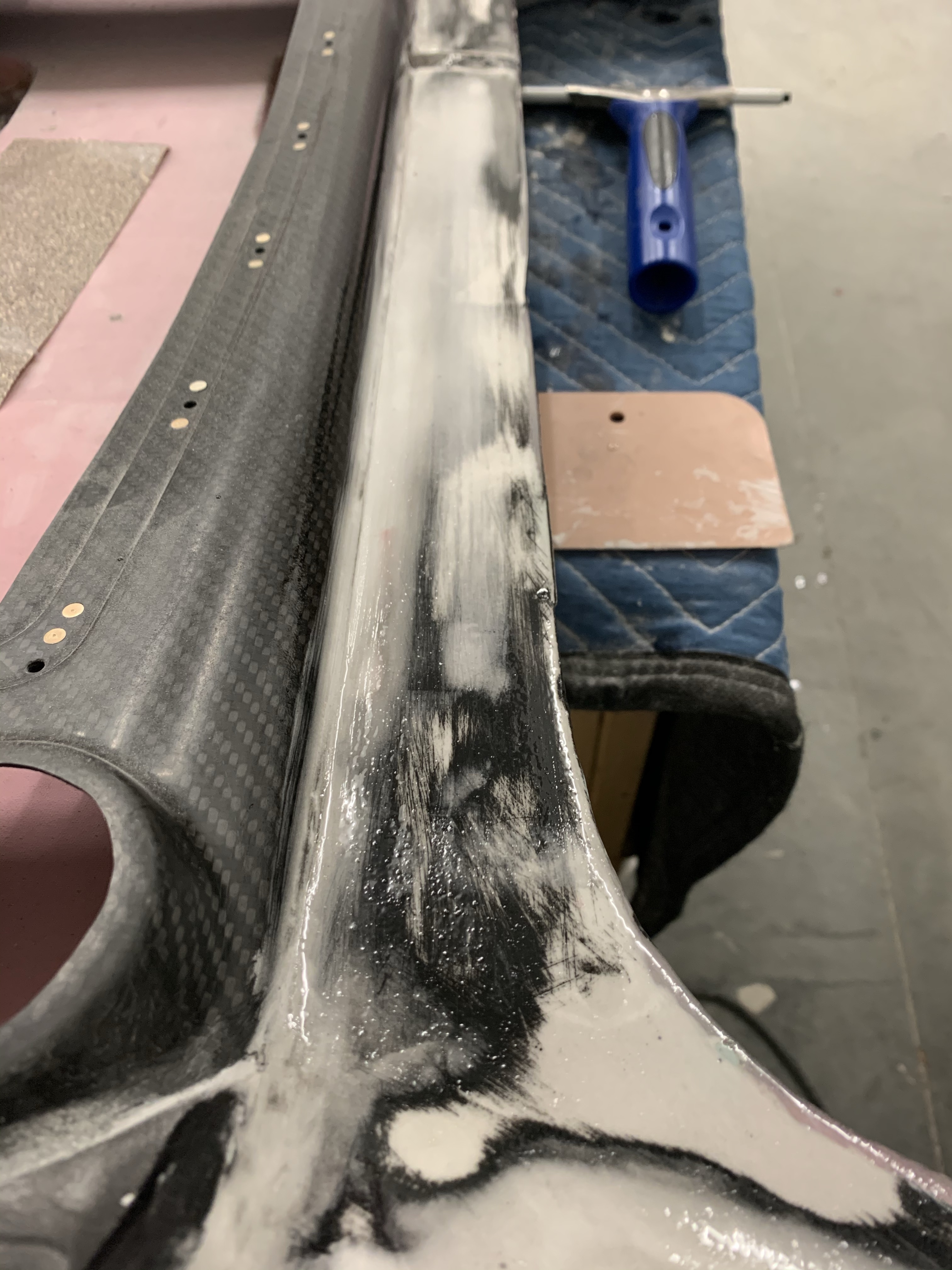
Once you’re happy with the contour of everything, you apply a skim coat of neat epoxy and I used a squeegee to move the epoxy around in all directions to fill in any pinholes. I then used a 4″ foam roller to smooth it out and let it cure overnight. The foam roller leaves some small “dots” from the nap of the roller which I will lightly sand after things cure.


I’m relatively happy with how it looks currently. By no means is it perfect, but I really just want something that is presentable and isn’t an eye sore. Next up is to paint it. The plan is to use a dark PPG epoxy primer and do a wet-on-wet application of PPG K36 high-build primer. There will likely be at least a couple of rounds of that building up the surface, block sanding, and repeating until the surface is as perfect as I can get it. Then a top-coat of paint will be going on after that. I’m planning of a charcoal and oxford white interior scheme, so this will be painted an Oxford White. I’m currently working of getting supplies together to build a temporary paint booth so I can shoot primer and paint in a reasonable atmosphere.