Indirect lighting from inside the cowl when drilling the skybolts can really misalign you. I started to also trace the inside of the hole with a fine point sharpie to get an even better view of exactly where the hole is and also use that to gauge walking the step bit in one direction or the other.
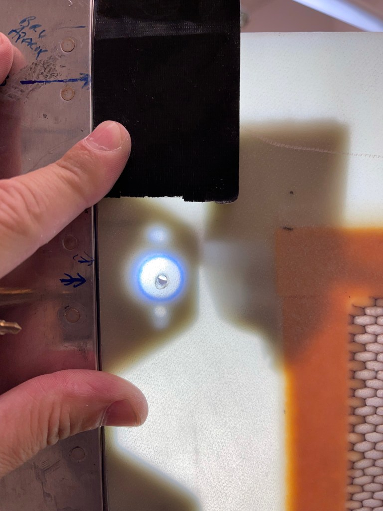
Even with that I’m ever so slightly off, although not by enough to matter.

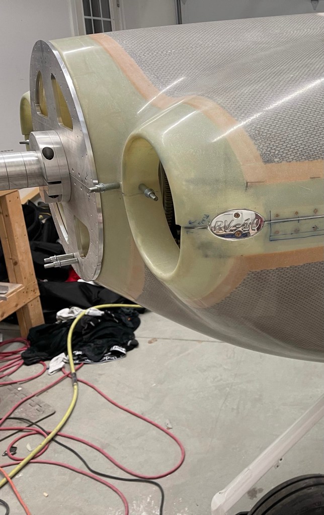
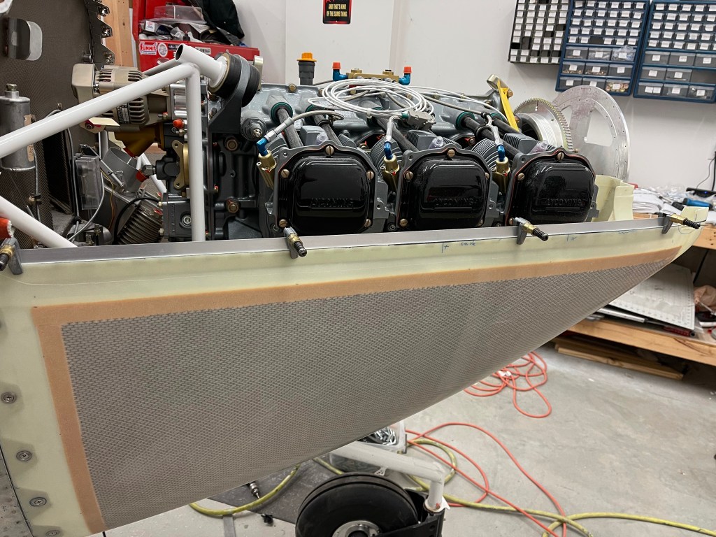
Below is a look down the left side at the firewall with some skybolts installed. Here you can see my small light that I used taped in place to more directly illuminate the hole.

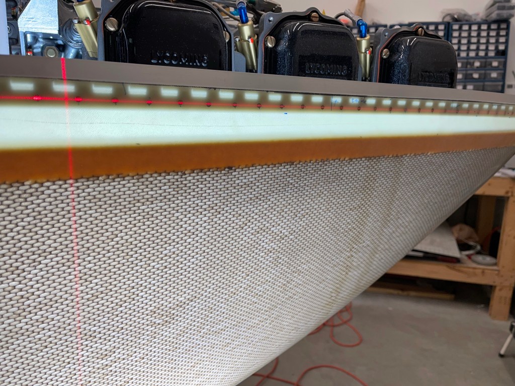
I then used a laser level to mark and trim the top cowling first. the 12″ Permagrit sanding block was used after getting close with a diamond cutoff wheel on the dremel tool.
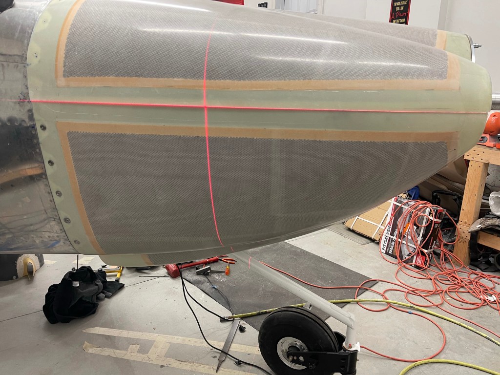
I then used the top cut to mark out the bottom cowl cut location.
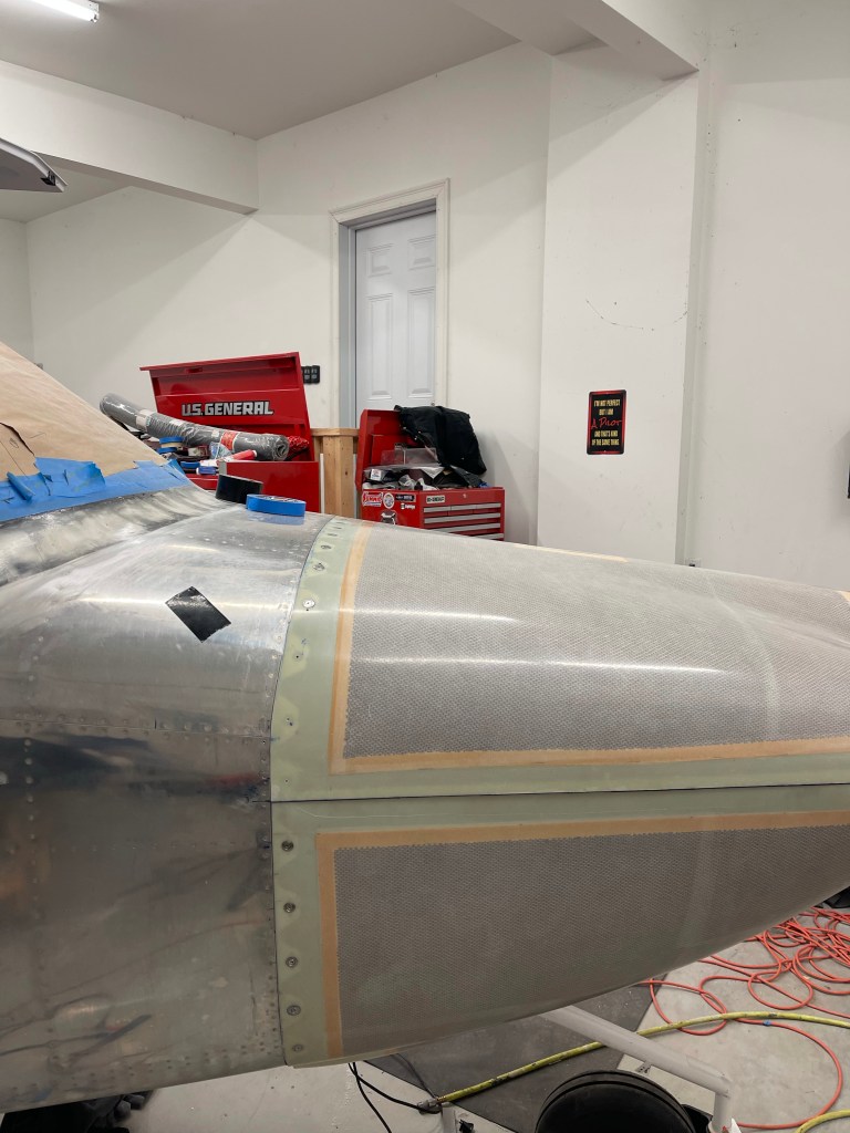

I trimmed close with the dremel tool and then used the sanding block to get it as close to perfect as possible.

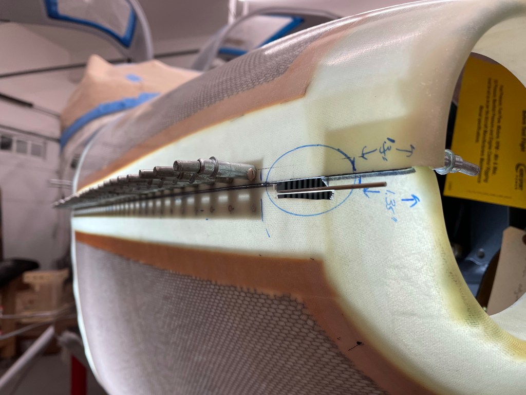
Once that was done, I marked the location of the hinge pin covers from Aerosport. Location was based on the plans.


With the hinge pin covers located, I then got to installing the side hinges. I shifted the hinge downward so the eyelids won’t show. I used a AN257-P3 length hinge on the bottom cowl and a -P4 length hinge on the top cowl to get enough flange to maintain edge distances on both the hinge and the fiberglass.


The same was done on the right side.
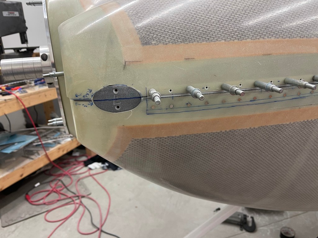
Use of the laser level to get the rivets all aligned down the hinge.
One thing I did was to drill a couple of turns with a hand drill in each marked rivet location prior to using a higher speed air drill. This created a slight dimple so the high speed drill wouldn’t wander once I was drilling through. Very little pressure was used and just let the drill bit do the work.

A view of the right side done and hinge pin in place (not yet cut to length)

I then cut out the spot where the aerosport hinge pin cover template was to be placed. I got close and then used a file to get it to fit tightly in the cut hole.

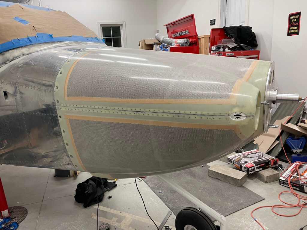
I then followed the Aerosport directions and added tape and wax to the template along with putting a micro slurry on the inside of the area. I also wetted out 4 layers of 9 Oz fiberglass and placed it on the inside. Once cured overnight, I used a thin woodworking saw I had from a previous task of cutting casings to cut through the Aerosport template and separate the cowl halves. I will say that the very front part where the 2 cowl halves overlap gave me a lot of trouble as I bonded them together and it took a relatively long time to get them apart and left me very frustrated. There is not a lot of room to work either to try to use small files etc.. to chip away at the bond. So use caution when doing this with a Showplanes cowl.. It’s pretty easy to waste 3-4 hours hacking away to get them apart again..

The end result of the recessed area I built up in order to install nut plates for the cover.

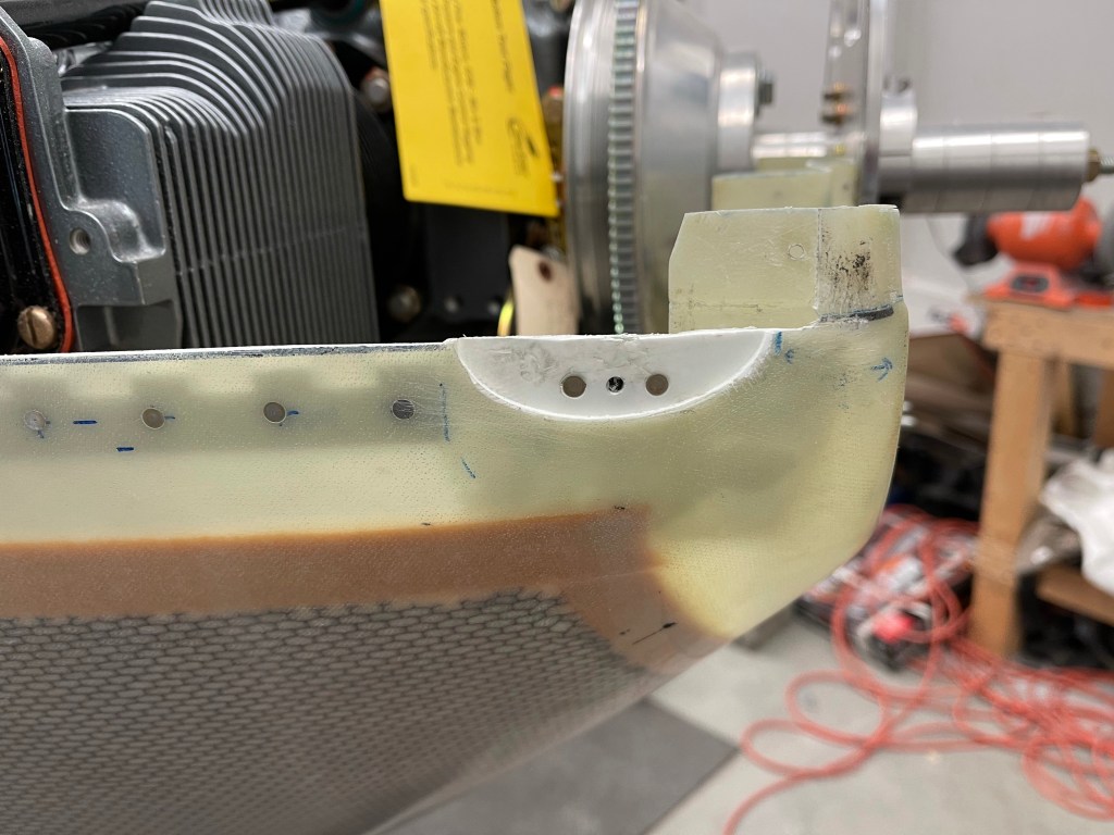
The center area of the added fiberglass was cut out to allow the pin insertion into the hinge.
Finally the hinge pin cover was test fit into place. This is at such an angle that if the hinge pin were to start to wander forward with vibration, it would stop the pin from working its way further out as the pin would hit this metal cover. From all accounts that I’ve seen.. the pin doesn’t typically do that anyways, but it would only be allowed to move approx. 1″ forward worst case.