Doors part 3 and Aerosport Handles

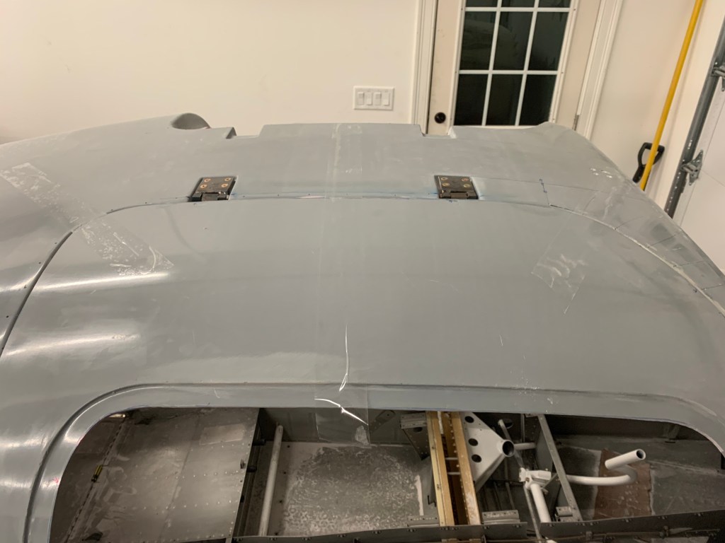
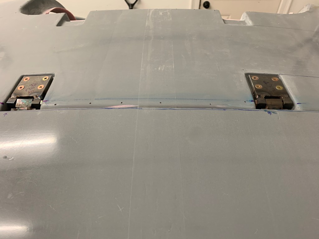
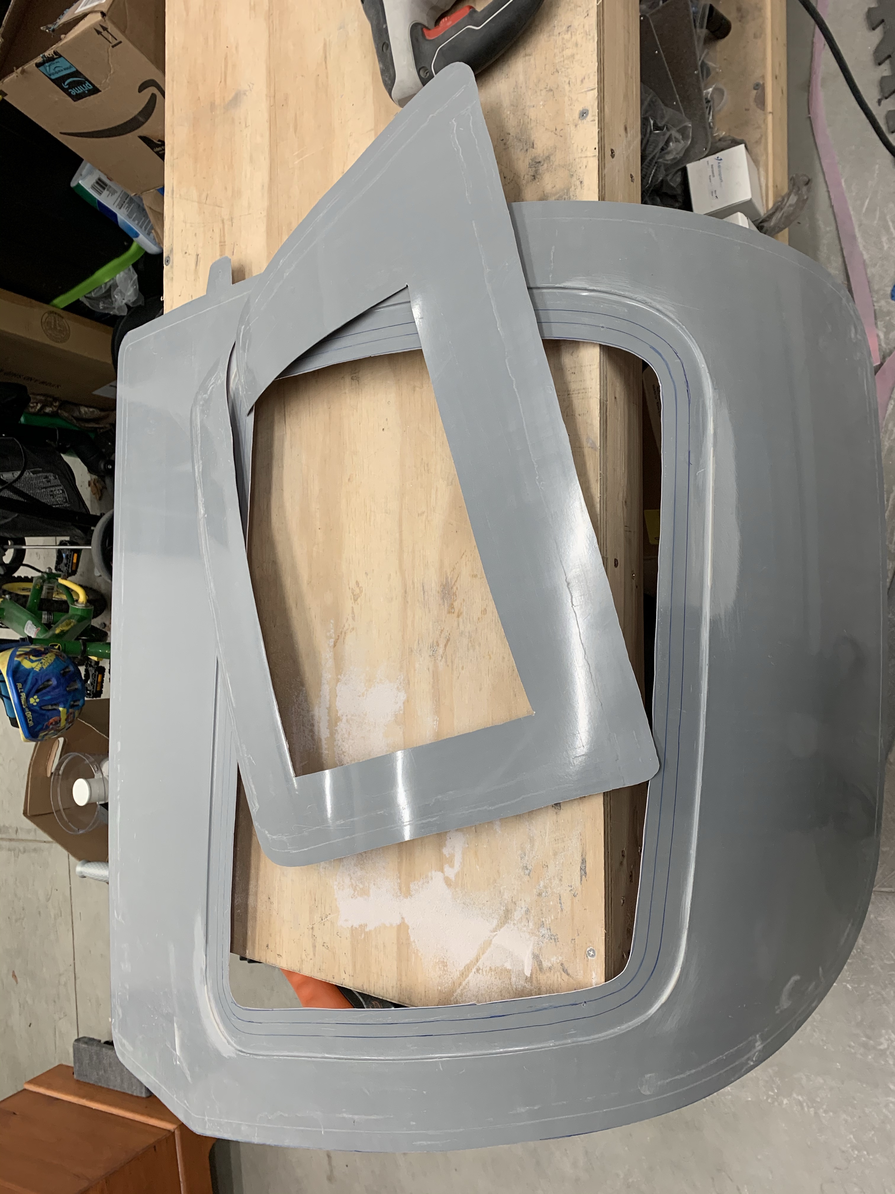
Once both doors were hung on their hinges and operational, I looked at the Airward Door main door hinge kit that I had bought. This is supposed to beef up the hinges by providing plates on both sides of the door, and I’m sure it does, but they do sit proud of the surface by at least 3mm. I just wasn’t happy with that prospect. It just looks really out of place not being anywhere close to flush with the rest of the cabin top.. After doing some more reading and research, I’m convinced that the stock way of doing the hinges is just fine. I may use the inner plates of that kit to provide support and nutplates for the hinge screws; or just use some nutplates on the door side of the hinges themselves. To be determined later. So with that, I countersunk the outer door surfaces for the screw heads and also have bought some countersunk washers that I’ve seen suggested.

Hinge Countersinks

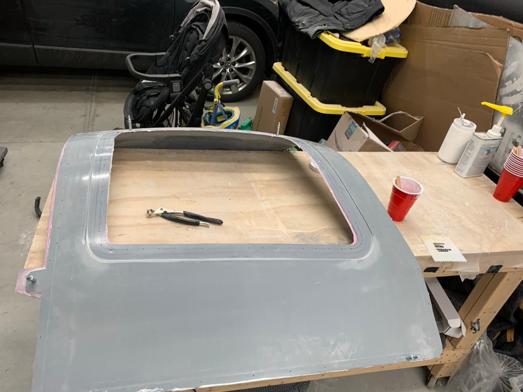
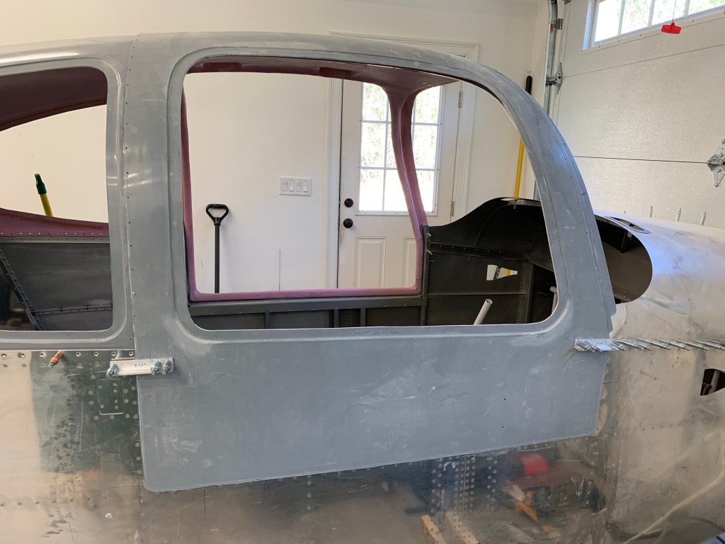
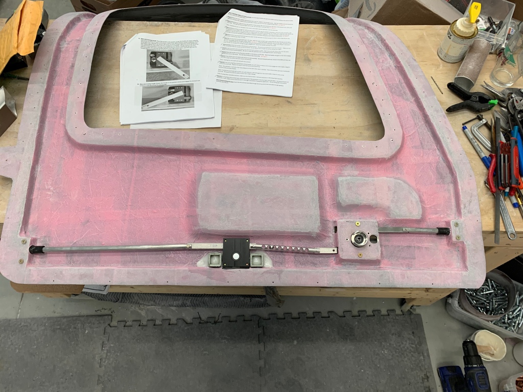
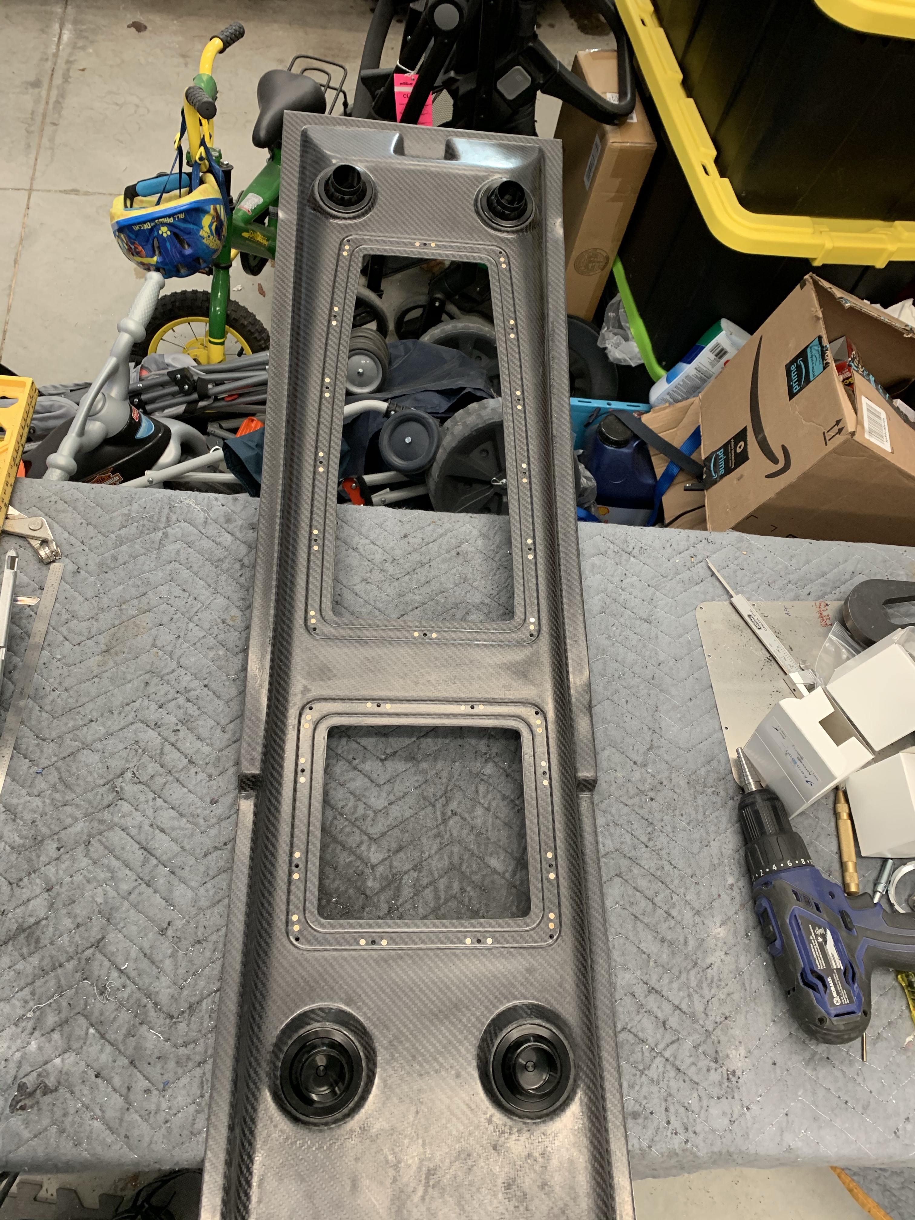
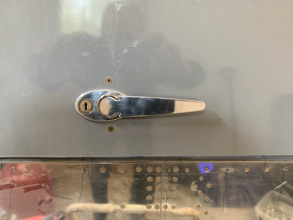
I then got working on the Aerosport exterior low-profile handle assembly. The next several pictures show how the exterior handle will look. It was pretty straightforward following the instructions from Aerosport on trimming the door for the lock and inner ring of the handle.

I then got back to re-assembling the door latch mechanism and safety wiring the pins to hold the racks to the forward and aft pushrods. The Planearound 3rd latch gearbox was reinstalled and the lock mechanism re-installed. One thing I had to take care of was some Parabeam material and epoxy had oozed out and block a portion of the void where the racks slide. I spent about an hour one night getting that relatively small chunk of glass out of the innards of the door so the latch mechanism would work freely. I had seen, after the fact, that some other builders had put some scrap aluminum just below the elbow cavity to prevent this and would certainly be something that I would suggest doing if I were doing it again. I got lucky in that it only happened in 1 of the doors and was relatively minor from what it could have been.

Forward Left pin safety wired to middle rack

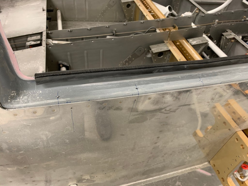
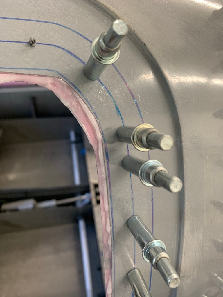
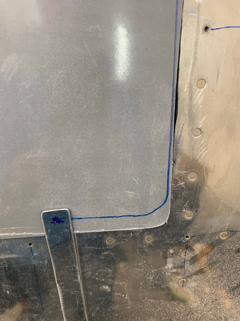
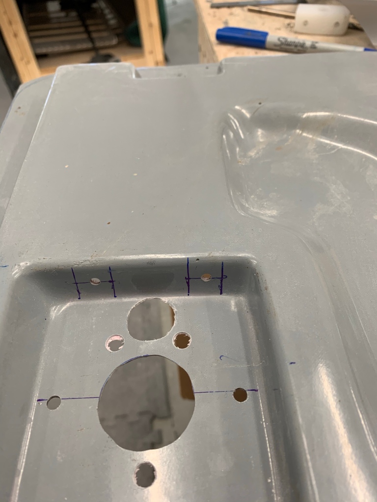
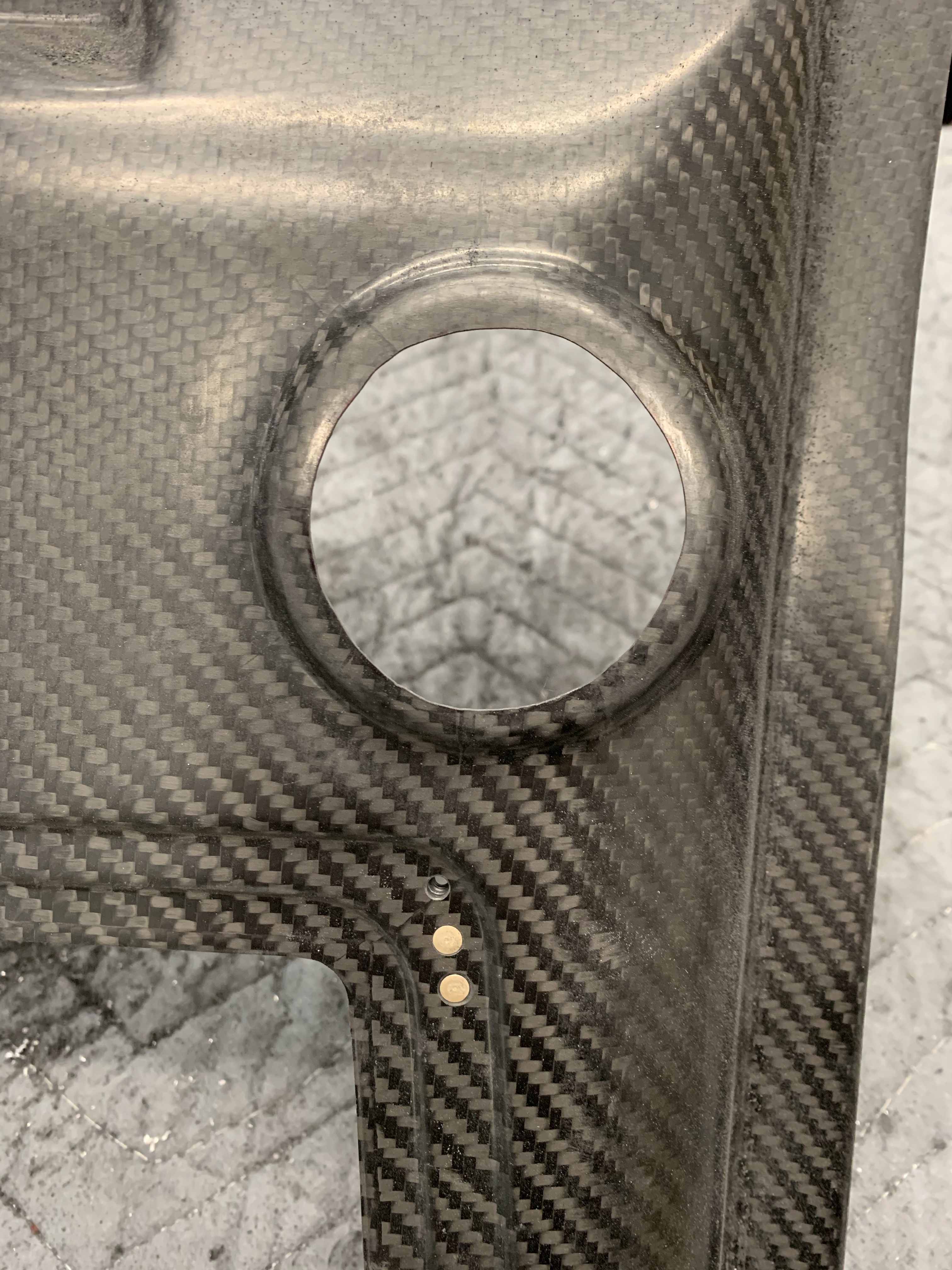
Once the door latch mechanism was back in and installed it was time to drill holes into the door frames to accept the pins and keep the door closed. I went against the plans of using a bolt ground down to a point to mark the spot where the pin comes out and instead used a method I saw on Dr. Mark’s build and using some math. I first marked the top and bottom of the door skin where the pin comes out. Then transferred that to the fuselage and used a square to further transfer those marks to the inside door edge.

Marking the pin exit points; top and bottom

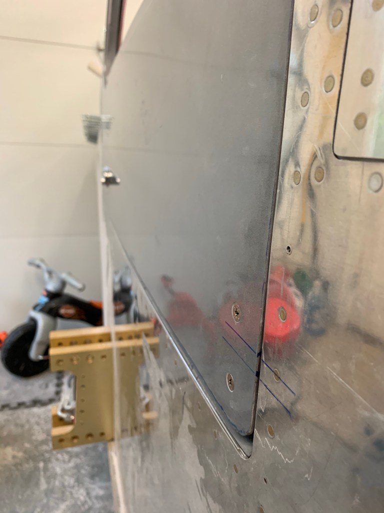
Then I measured the distance from the outside of the door to the inside of the pin and transferred that measurement to the inside of the door frame.

Measuring the door to pin
Transferring it to the door frame.

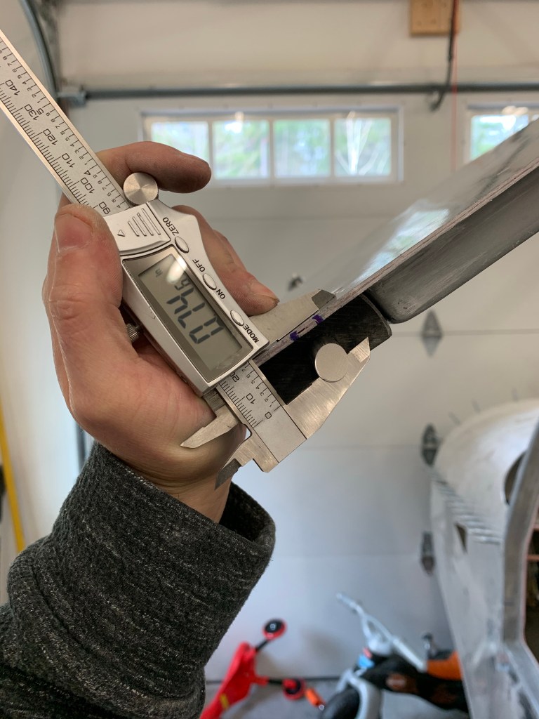
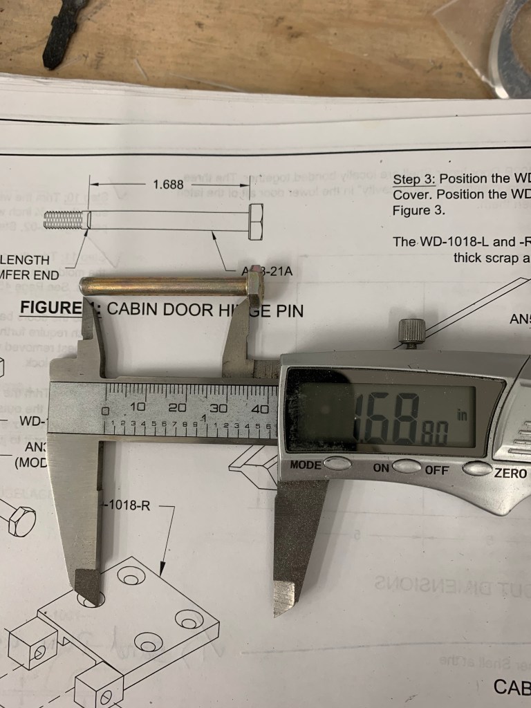
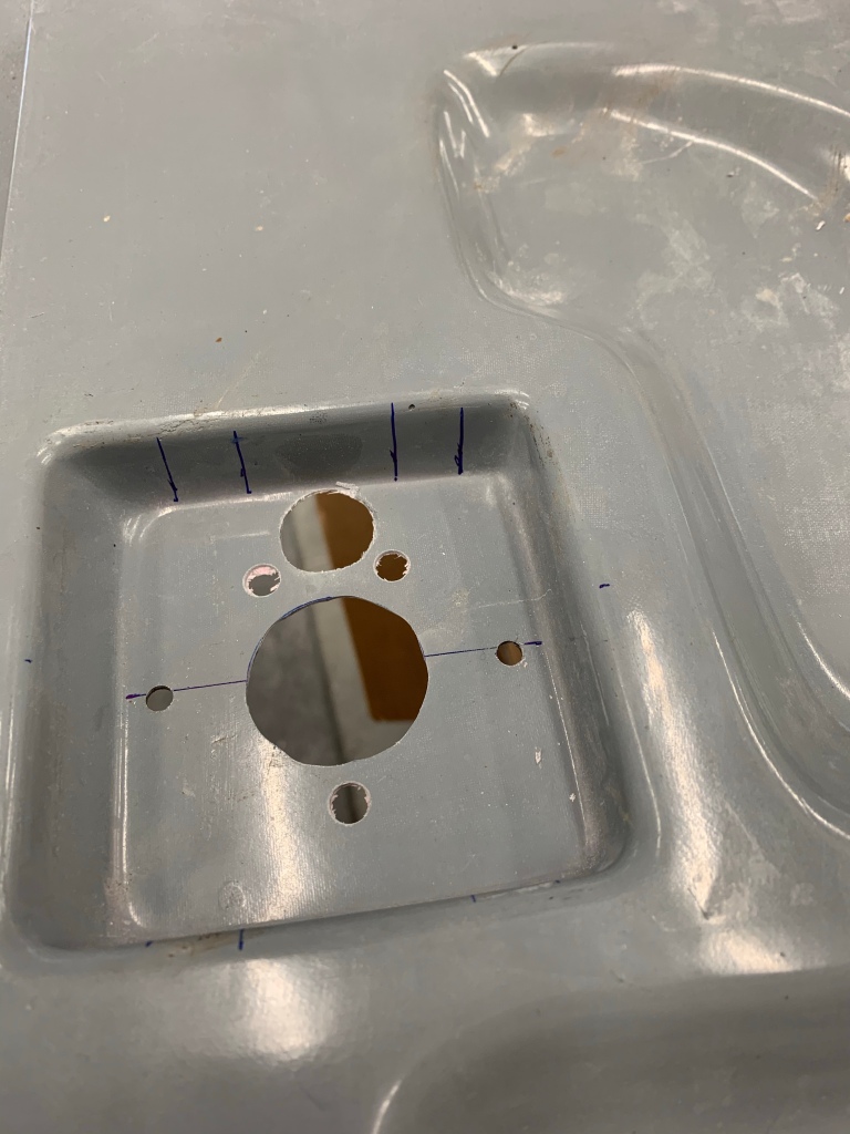
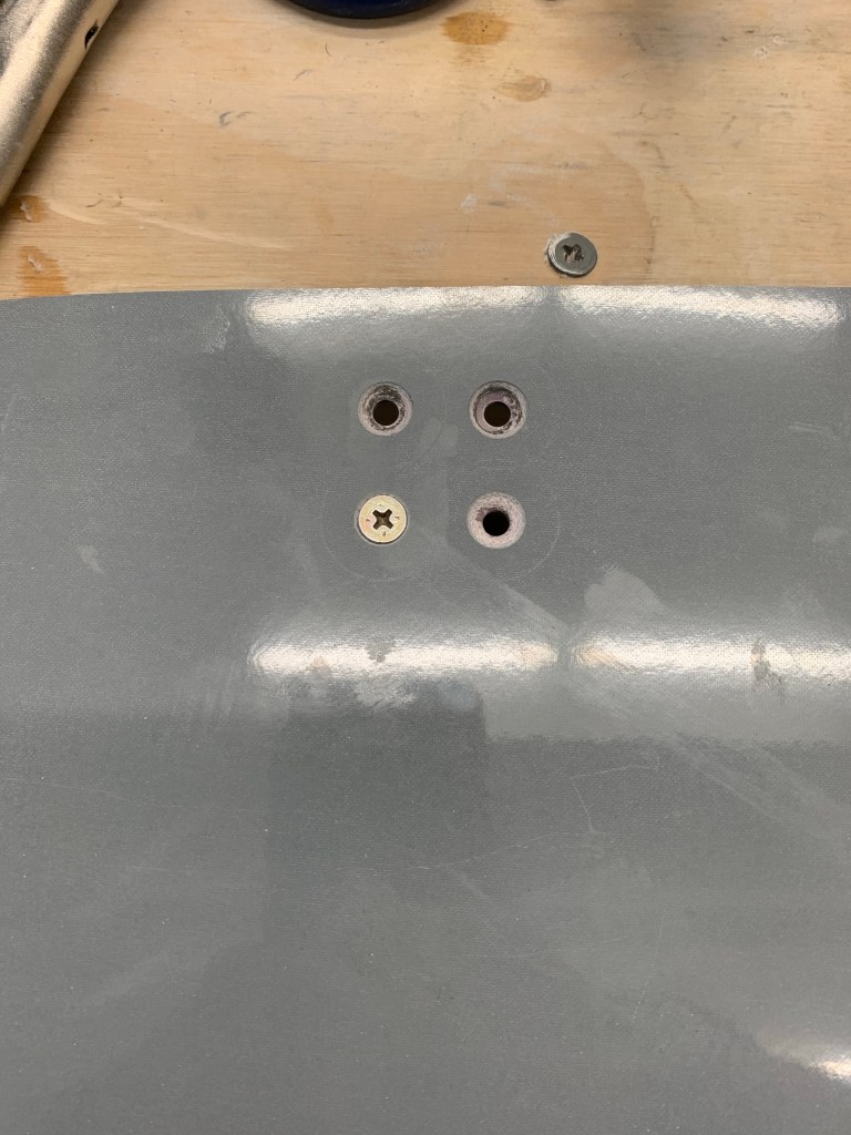
I then measured the thickness of the pin, which was 14/32″ and divided by 2 to mark the center points of the where the pin would be as shown below.

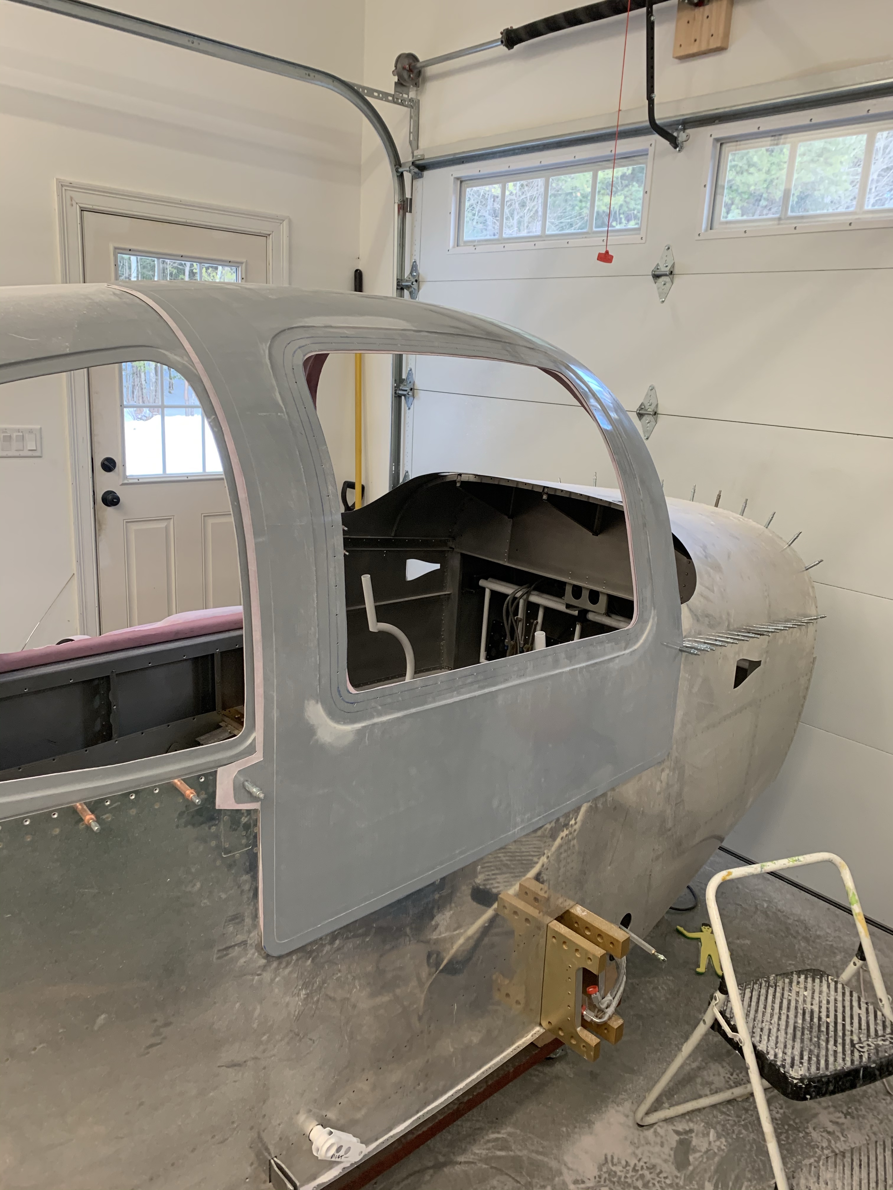
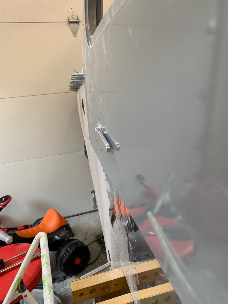
Then I under sized the drill working my way up from a #30 all the way to a 10mm, which is what I had and was smaller than the called out 7/16″ in the plans. I then used a dremel tools with a grinding wheel and a small file to work slowly to get the pin to go through the hole with no extra slop. This step required a lot of patience and repeated grind a little away and recheck, but in the end it paid off and the holes for the pins are nearly perfect and keep the door flush to the fuselage surface.

Final hole for the pin to go through

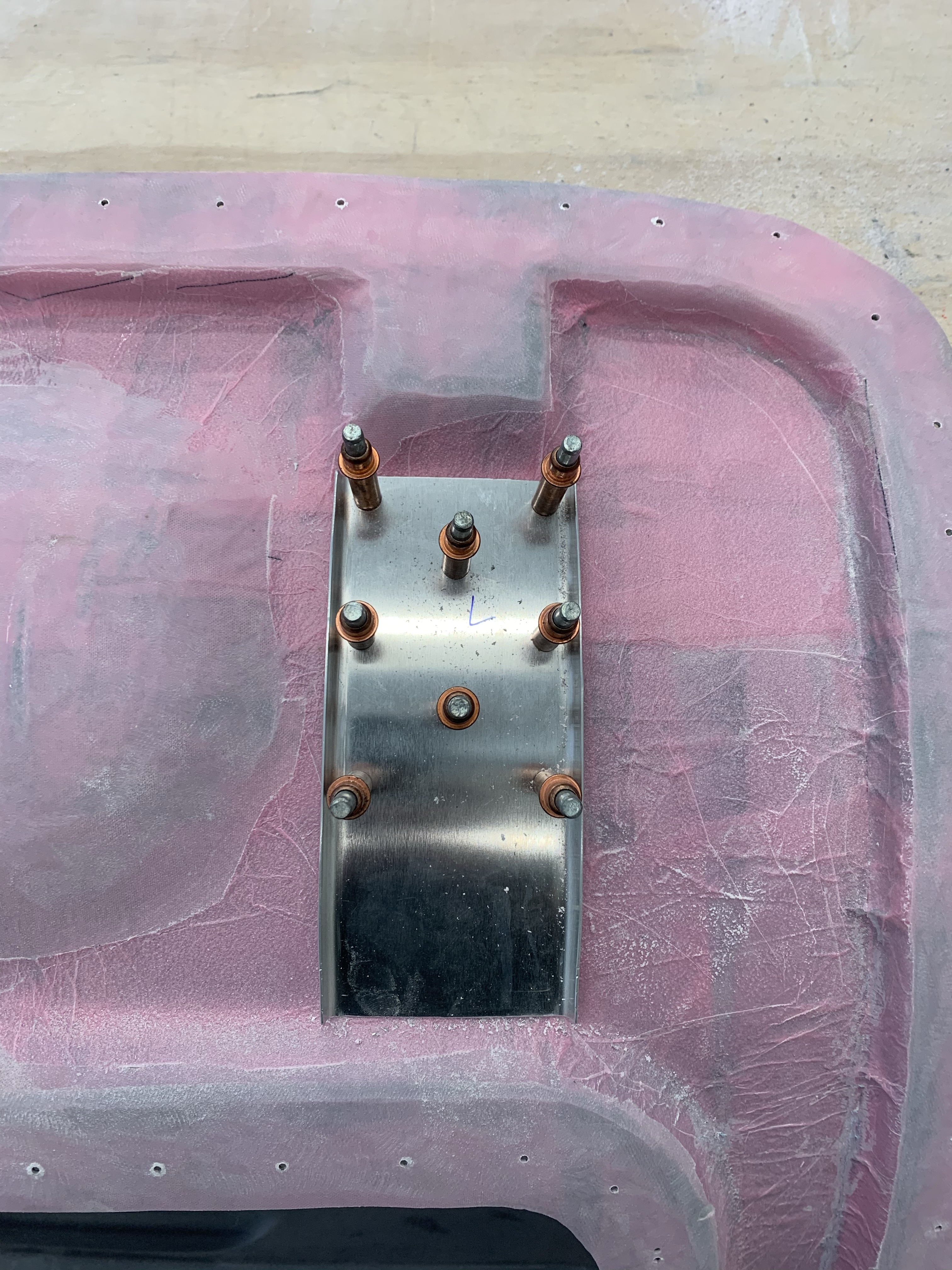
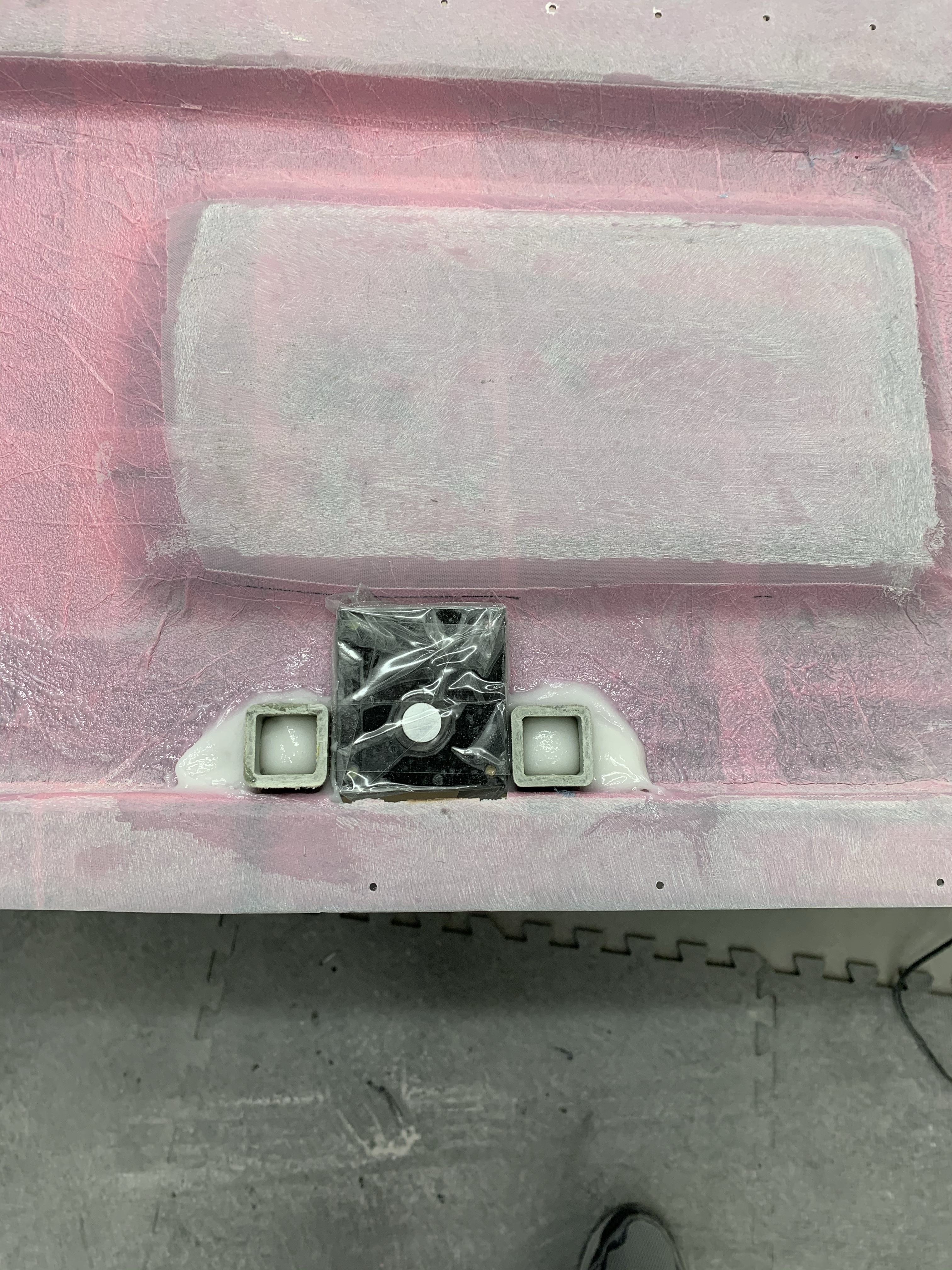
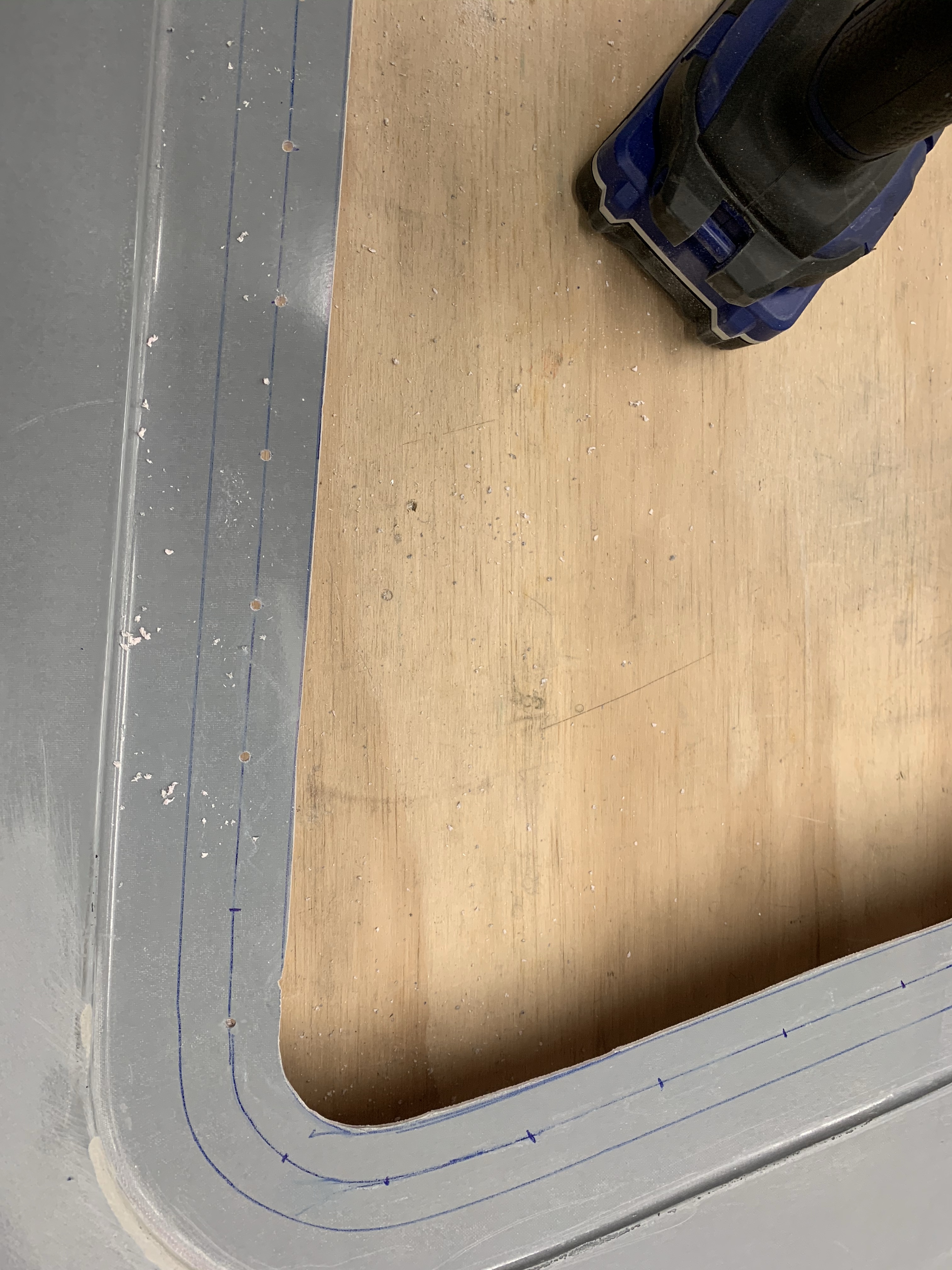
Next up was to get the Planearound guide blocks into place. The best way I found to drill the 2 holes needed to hold these in place was to close and latch the door and place the block on the inside of the door with the pin going through the center hole as shown below. In most cases, without trimming, these hit up against the outer skin and prevented them from rotating or moving while drilling the holes. I then trimmed those guide blocks as needed when putting the on the other side of the door frame.

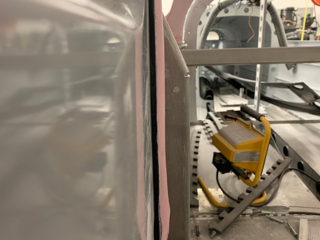
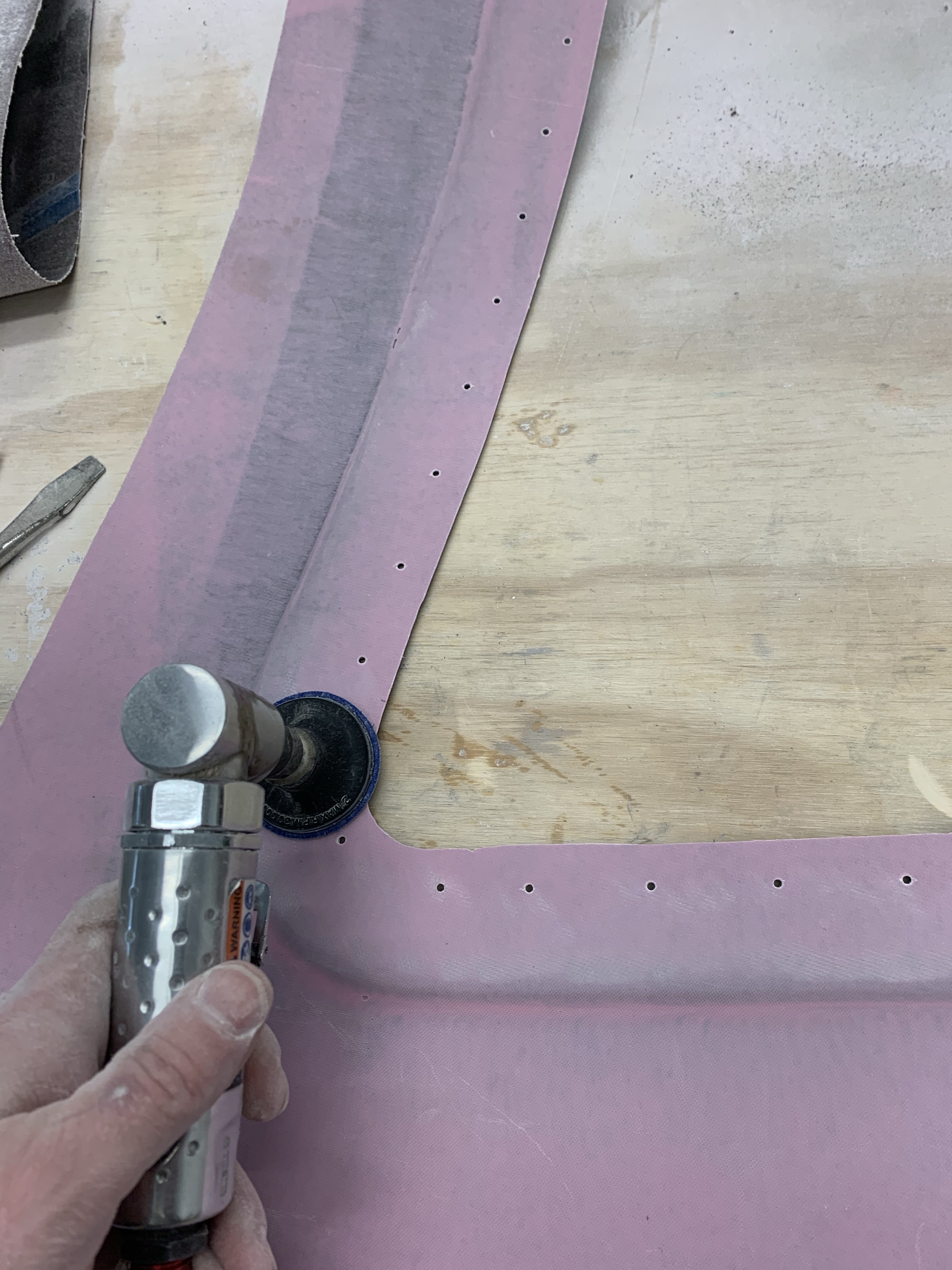
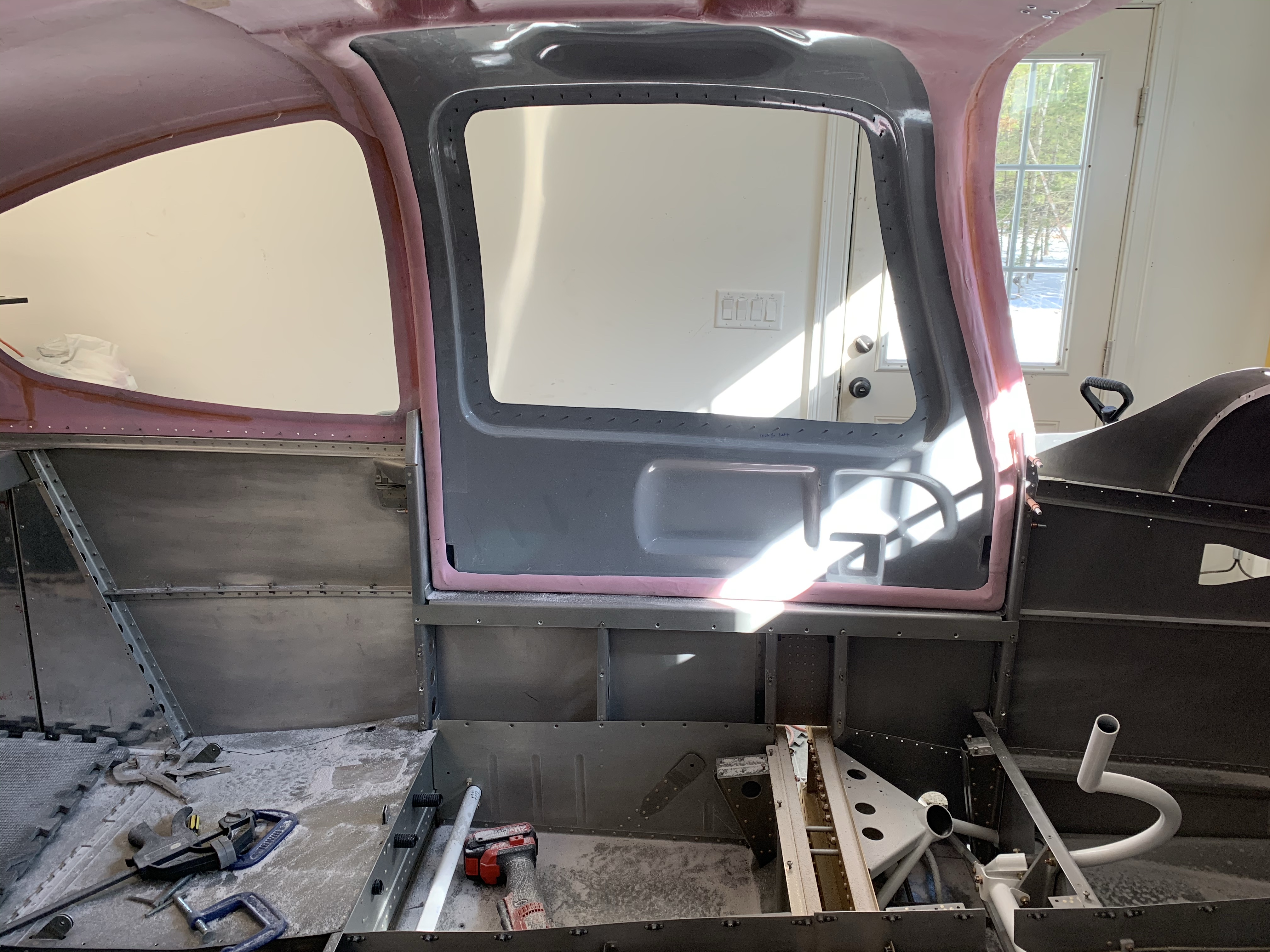
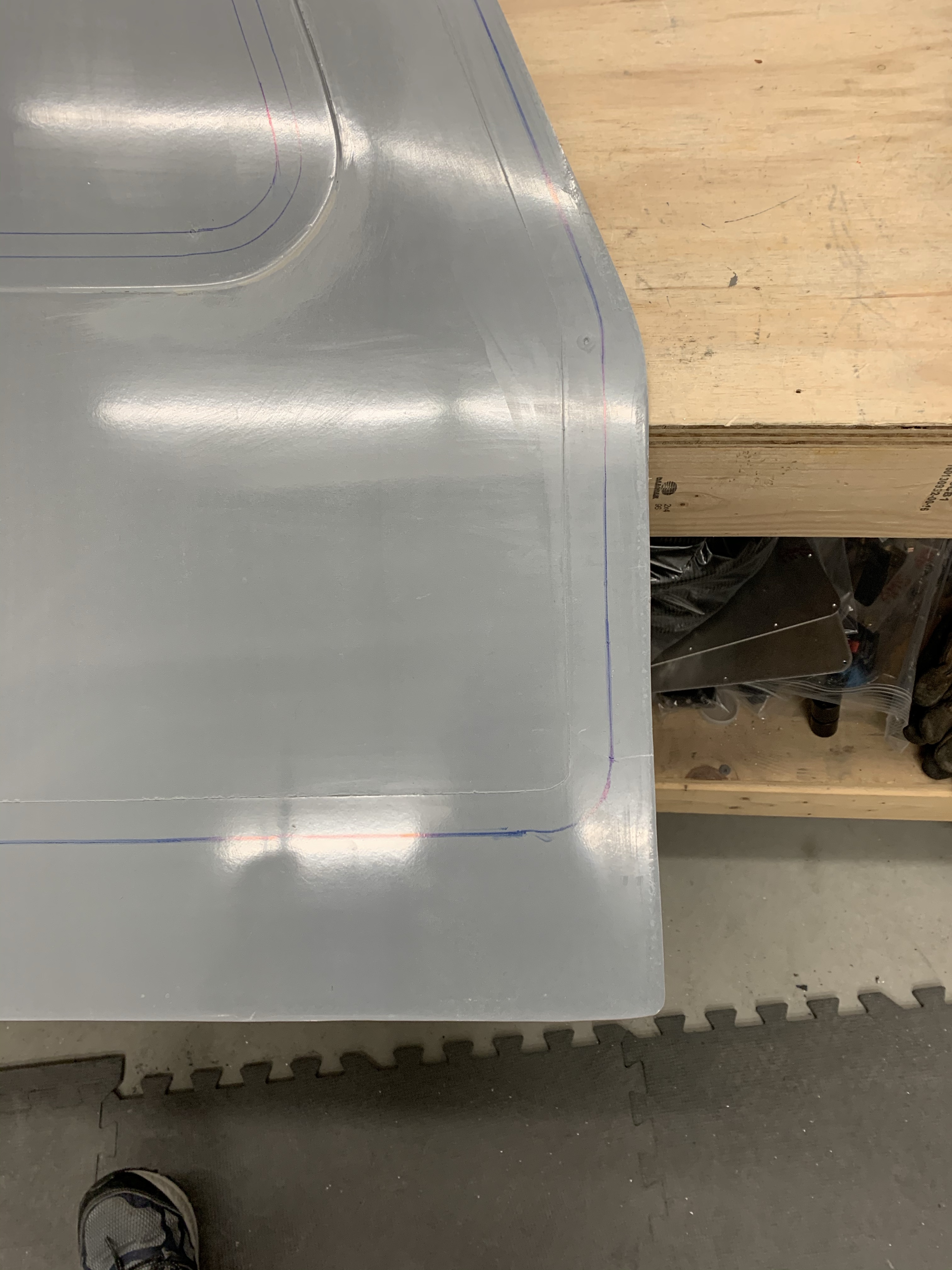
While I had previously sanded for a very close to 1/4″ gap around the doors for the McMaster seal, as you can imagine, this fit of the door closing with the pins engaged required a little more sanding in some spots. I also bought the 3/16″ grip McMcaster seal so I sanded the inside of the cabin top to get that as consistent as I could. For the most part, I don’t see much of a need to build up the door gutter for the seal as many others have done, as I had to sand down most of it to get to a decent 3/16″ edge thickness, but we shall see. I just may do it anyways to get a perfect fit. There are a couple of spots which are thinner and squeezing the attachment point seems to hold it on fine.

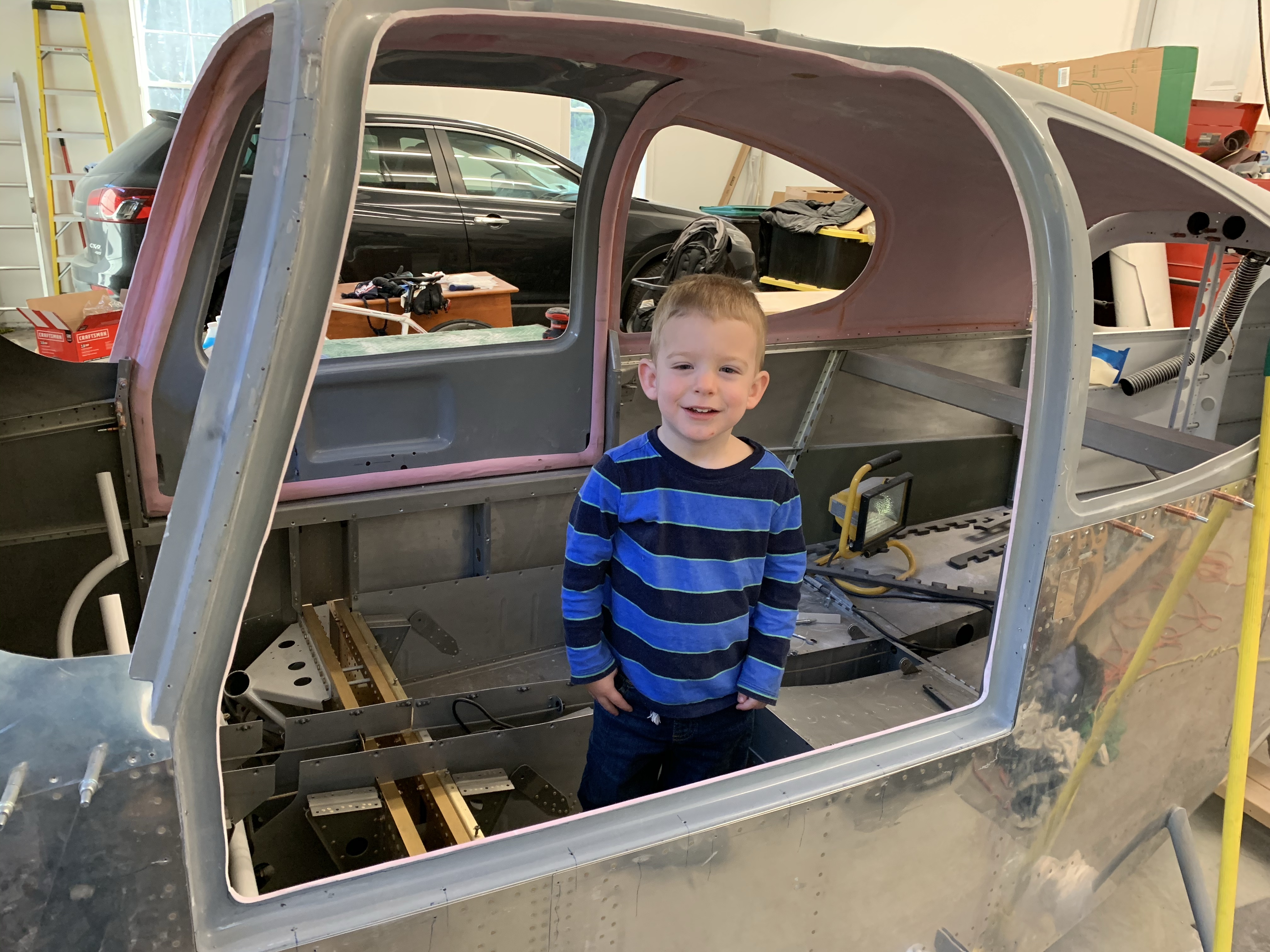
A quick video of the right door progress.

One door down (up), one to go.

After the last post, I cut the edges (rain gutter) of the door openings on the cabin top to Ivan Kristensen’s measurements. Approx 1 5/16″ along the top, 1 1/4″ in the top corners, going down to approx 1″ along the sides and bottom. I then drilled a 1/16″ hole in a skinny piece of aluminum to mark a 1/4″ line from the inside edge of the door. This gap will allow room for the McMaster door seal bulb to sit in and allow the door to close and squish the seal bulb properly.

pretty close to even 1/4″ gap.

I then test fit the McMaster seal. Initially just a section along the bottom of the door, then all the way around. I will still need to sand down a couple of high spots in the corners as the thickness of the fiberglass is > 1/4″. I might also need to build up some areas using the seal as a template for an epoxy/flox mix, although I’ve seen some builders say that they didn’t need to do this.. so guess I’ll see what makes the most sense a little further along.

Door squishing the seal
Test fit all the way around the right door opening

Then it was on to preparing the hinges. You use an AN3 bolt with the threads cut off as a hinge pin. Then proceed to get the hinges up in their pockets and match drilling the 4 holes. The main thing here is identifying that the hinges are different and getting them in their proper location. You can actually see in the hinge pin picture below that the hinge “legs” where the pins pass through actually have an offset to them to match the curve of the cabin top. It’s important for the high side on the forward hinge to point forward and the high side of the aft hinge to point aft. The lower points should be inboard.

The door was put into place, taped up top to hold it in place and the 4 holes on the door side match drilled.

Closeup of hinges

The end result is a functional door!!

Bonded!

I was a little nervous walking into this part of the build. In the end, I’d say it wasn’t as bad as I had expected. My door halves are now bonded together! Before starting, I used packing tape to cover the cabin top all around the door opening so that any epoxy that squeezed out wouldn’t bond the door to the cabin top. I worked on one door at a time and only mixed enough epoxy and Cabosil for one doors worth. The plans have you first spread some straight epoxy on the three areas that actually bond the door together, the elbow cavity (shown below with fiberglass parabeam on it), the cranial cavity at the top of the door, as well as the latch cavity. You then wet out the Parabond material previously cut with straight epoxy and put it in place on the inner door shell. Then add some Cabosil to the mix until it thickens enough to not pour out of the cup. That mixture was then spread over the remaining mating surfaces (the window flange and the outer door flanges).

Parabond on the elbow cavity

Once done, the outer door shell is placed on top of the inner shell and cleo’ed along the lower edge and 2 places in the upper window flange prior to placing it onto the fuselage.

Door shells together and minimally clekoed together

Attached to the cabin top and cleko’ing the window flange. A reasonable amount of epoxy squeeze out along the edges.

The entire door was cleko’ed to the cabin top so that it cures into the outer shape of the cabin top. The plans have you use clamps, tape, and weights. This, to me, is a much better method that I’ve seen other builders suggest.

I then left the garage heat on 60 degrees and let the doors cure over 2 days. I took the doors off and removed all the Clekos.

I then cut the window flange down to the 3/4″ line previously marked. Additionally, I made up a couple of angles and match drilled them to the forward and aft index holes and then drilled a couple of holes into the door to hold the doors in place so they could be trimmed. This will also allow me to keep the doors in the same position for all other door work without them moving.

One of the next things is to trim the outer door edges to within 1/8″ of the scribe line, which I did. I then did something that I saw on Dr. Mark’s blog in terms of making a tool to mark the inside edge of the cabin top on the outside of the door. I riveted 2 pieces of metal together and bent one piece at a 90 degree angle to follow the inside cabin top door edge. I then drilled a 1/16″ hole aligned with the 90 degree bend to trace on the outside of the door where the inner edge was. That was the line I used to trim to for the entire perimeter of the door.

Tools to mark the inner cabin top edges on the outer door.
Tool in action

I then had my buddy come out and check out the progress.

This is the result after trimming to the line made by the tool. I’m at the point of needing to trim the cabin top rain gutter back some more in anticipation of using the McMaster door seals. The door won’t fully sit flush with the cabin top just yet until I do that. So that and door hinges are up next.

Doors Part 2

Slow progress lately…

This part of the build is somewhat challenging in that I am reading from 3 different sets of instructions from 3 vendors and trying to understand what to do next. Next up was to grind down the stock pin blocks in order to drill #12 holes into the doors to hold the blocks in place.

Then you take the new oversized blocks from PlaneAround and sand them to fit well into the recessed pockets of the door. Then match drill them to the holes you drilled with the stock blocks.

Shaped Pin Blocks

Then it was time to take the striker plate from the Aerosport Low Profile handle kit and center it in the handle pocket by rounding off the forward corners and drilling the holes needed for the inner ring and lock.

Once that was done, the inner handle assembly was completed per plans with some modifications based on the Aerosport instructions. One modification that I did was to cut a longer slot in one side of the handle assembly so that the handle would only lock in the closed position and not the open position too. I didn’t take any pictures of that.

Modifying the interior handle for the Aerosport handle on the exterior

I then took some scrap metal and made it the width of a rack without teeth and just long enough to stay in the handle gear mechanism while marking the sidewalls of the handle cavity where the racks will come out and need a hole for clearance.

A rack and piece of scrap to be used to mark cavity
Scrap piece coming out of gear mechanism to mark sidewall.
Marks made for the width of the racks
Holes drilled in center of these marks

Clearing out the area for rack clearance.

I then assembled the push rods with the Planearound 3rd latch system and got everything the way I wanted it. This allowed me to mark the push rods for 1.5″ protrusion from the sides of the door and about 1/2″ retraction into the Derlin pin blocks.

Long push rods marked to cut down to proper length.

I’m also using the angled machined pins from Planearound. The push rods were cut down 2 more inches to accommodate the length of the pins themselves, and tapped with a 5/16″ x 24 tap to attach the pins with a screw.

Planearound pins installed in push rods
Inside of the door with handle all finished.
The interior workings of the door handle/latch mechanism before door halves bonded.
1.5″ pin protrusion when handle closed.

Below is a quick video that I made to explain the operation of the door handle and pin/latch operation.

Doors part 1

Knowing that there will likely be several posts about doors… I will do posts in “parts” Otherwise I will quickly run out of ideas for post titles. Unless, of course, there’s something more clever that comes to mind at the time.

I’ve decided to postpone bonding the doors together just yet to get the Planearound latch , door handle mechanism, and Aerosport exterior handles all installed. Nevertheless, I did sand down the spots on each shell depicted on the plans that will touch and bond together.

Trying out a sanding pad on a pneumatic die grinder

Next you put the door shells together using the dimpled index holes in the fiberglass that were drilled in each half. Like so many others, mine didn’t line up very well. The aft index hole lined up okay, as did the forward index hole (although it wasn’t aligned with the fuselage hole in the plans). It was aligned with the last hole of the upper forward fuselage about 4 holes up from what the plans say. The index holes in the corners of the window were pretty much useless. There was 1 on 1 door that did line up and another on the other door that was close, but the others weren’t even close. Doing some reading this seems to be fine, you basically make sure the door is centered the best you can. Mine seemed to be fine using the aft and forward index holes, so I went with that.

Right door attached to forward and aft index holes

Then you use a hole finder (seeing I had one) to perfectly match drill the open rivet holes in the fuselage with the door shells. This allows a cleko to be put in and the doors held tight to the fuselage.

Hole finder to drill the door shells perfectly.

Once the bottom holes were done along the fuselage, you’re supposed to tape the upper part of the door to the cabin top. Then match drill and cleko the window opening. I had read of others drilling holes along the door pillars and cabin top to hold the door shells very tight to the fuse and not have to rely on tape. To me, this is a much better method that allows the door shells to hold the shape of the door opening much more precisely. It may not be obvious from the picture, but the door shells are still oversized for bonding so they make contact with the outer surface of the door opening in the cabin top. This is what allows the door to be shaped to the cabin top when bonding.

Right door attached to cabin top/fuse.

Left door done too showing clamps that were used while drilling the pillars.

A view from the front after both doors done.

Inside of pilot’s door

An example of extra holes drilled in the cabin top/door pillars

Next up was to drill and attach the door strut stiffener. This is a simple match drill holes.

I then hopped over to start working on installing the Planearound center latch system. First is locating the proper position, cutting out a slot on the bottom of the raised door edge, and also drilling and slotting a hole for the shaft.

center cam gearbox and markings for the cut.

After drilling a 1/2″ hole, and making a slot for the shaft in the gearbox. 

I then drilled the 4 holes that will hold the gearbox in place and countersunk them in each door and prepped for attaching the supports for the cut area of the door. I mixed up some Epoxy and cabosil first as I will attach both the door strut and these door cut supports all at once. Once I did the door strut supports with Expoy and Cabosil, I didn’t have too much left, so I added more epoxy and thicken it up with flox. So I ended up with a mostly Epoxy and flox mix with a tad bit of cabosil too.. No big deal. I wrapped the gearbox in packing tape so it doesn’t accidentally get adhered to the structure and added a generous blob in each corner with the support pieces in place.

Gearbox taped and supports added with Epoxy/Flox. 

Door Strut support plate cabosil’ed in place. 

Now I’ll wait for these pieces to fully cure before continuing.

More Cabin Top, Overhead prep, and Start of the Dreaded Doors

A little more cabin top work in locating the center of the top to align the center support bar. I drew 2 lines at the recess for the door hinges, extended them to the front of the top,  and then measured the center point between those 2 lines to find it. That method seemed to work well.

Center support bar in place.

One thing of note is that section 44 (Wing attachment) is the last section of the Fuselage section. I will be skipping this for now as it’s mostly working on the fairings that go between the wings and the fuselage as well as tank vent lines etc… Seeing my wings are in the basement still, and I’m not sure I have a ton of room to do this in my garage anyways, I’ll likely skip until I get to the airport and have the wings permanently on the plane.

So now some bouncing around in the plans, as well as off plans, will start to happen. I turned my attention to prepping the overhead console as much as I can. This involved match drilling holes in the joggles for the metal covers plates, drilling, countersinking, and installing nutplates.

Then onto cutting out holes for the overhead air vents. A little geometry to find the center of the circle to start cutting a hole. I originally attacked this by trying to drill a hole in the exact center and using a unibit to cut the hole. I have one that is pretty big and just shy of the size I needed. I figured I’d finish up with a little sanding/filing to get it right. In the end, once I went above a 3/4″ hole, it started getting off center for whatever reason. So I found it was best to just lay the retaining nut for the vent on the circle eyeballing it for center and marking the inner edge for the cut. Then drilling a large enough hole to get my jigsaw blade in there to finish it up. Worked out well. Maybe not 100% centered perfectly, but not too bad.

Geometry to find center of circle

Initial hole drilled. Looks good. 

All nutplates are complete

Overhead air vents in place.

An example of one of the holes cut out for the air vent.

That’s about what I can do with the overhead console for now. From what I’ve read on others blogs, it’s best to have the doors rough fit prior to attaching the overhead, so I’m bouncing onto starting that section.

The RV-10 doors are basically fiberglass shells (inner and outer) that the builder has to bond together. The first steps of getting the doors going and initially fit to the cabin top involves marking a bunch of lines for both trimming and eventually holding the doors together during the bonding process.

Marking Window Joggle lines

Marking the outer trim lines.

The easiest way I’ve seen to make these marks is by using a popsicle stick with holes drilled through at the various dimensions called out in the plans. This way you can insert your fine point sharpie through the hole and trace a line that is that distance away from the reference point, which is usually a joggle or raised structure easy to slide the stick along.

Tool for marking trim lines

Trimming and making dust (while making sure not to breathe it in)

Window area initial trim.

And finally marking along the 1-1/4″ line about every 1.5″ and drilling a #40 hole.

I’ve now started working on the outer door shells and will be soon starting the initial fit to the cabin top.