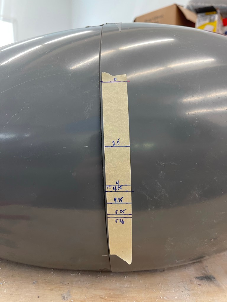
The Showplanes cowl is one of the last major fiberglass pieces to be worked on. The instructions basically tell you to follow Van’s instructions with a couple of exceptions. So I got to putting the upper and lower halves together and marking the upper cowling for trimming to meet the ratios needed to make a perfect circle for the spinner/prop as well as the air inlets on either side. Here you can see the mark made using a straightedge.
Staightedge used to mark uniformly across the top cowl.
Double checking that the radius is 7.5″ (15″ diameter)
Getting close now with some trimming
Using the prop tool to double check the prop area circle.
You then clamp things in place and drill holes in the flanges to hold this position.
I chose to just do a single cleco on either side of the inlets as well as one in the flange between the inlets and the prop area.
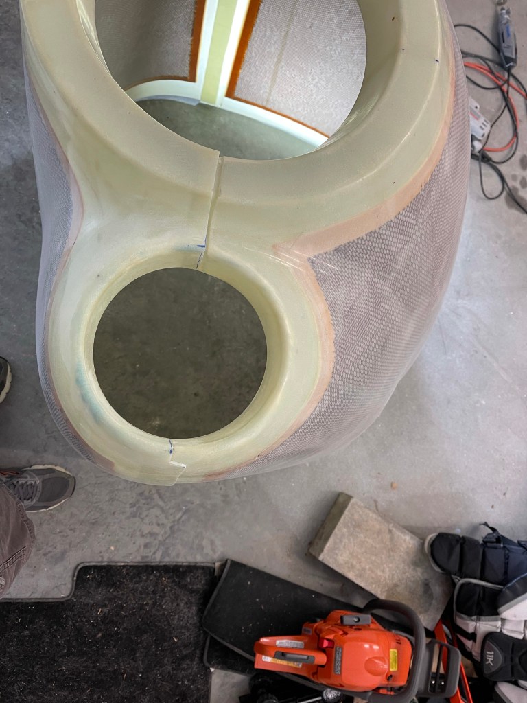
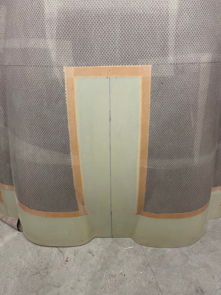
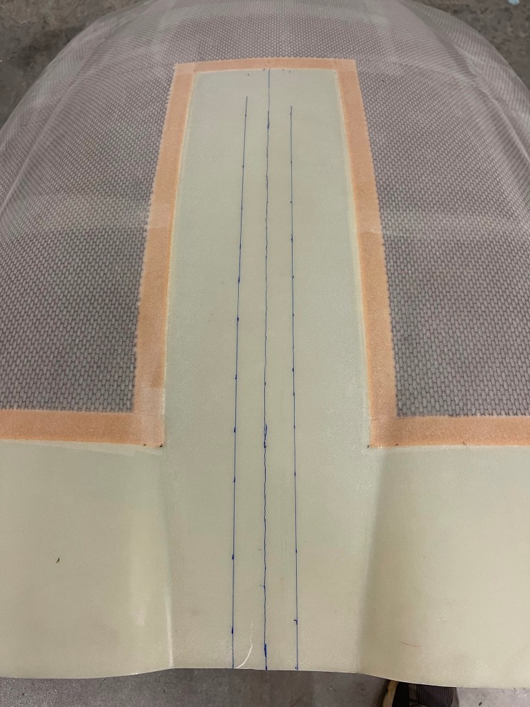
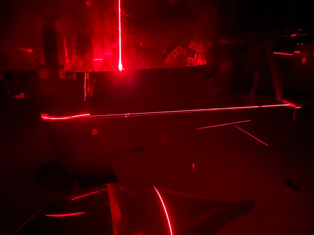
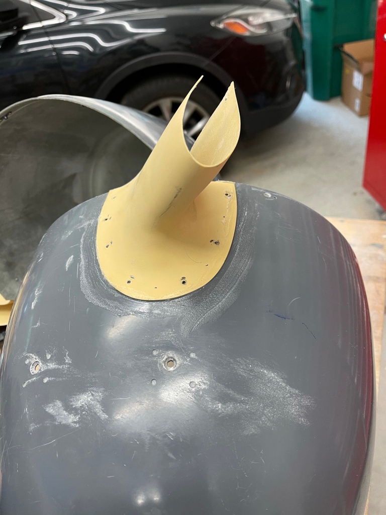
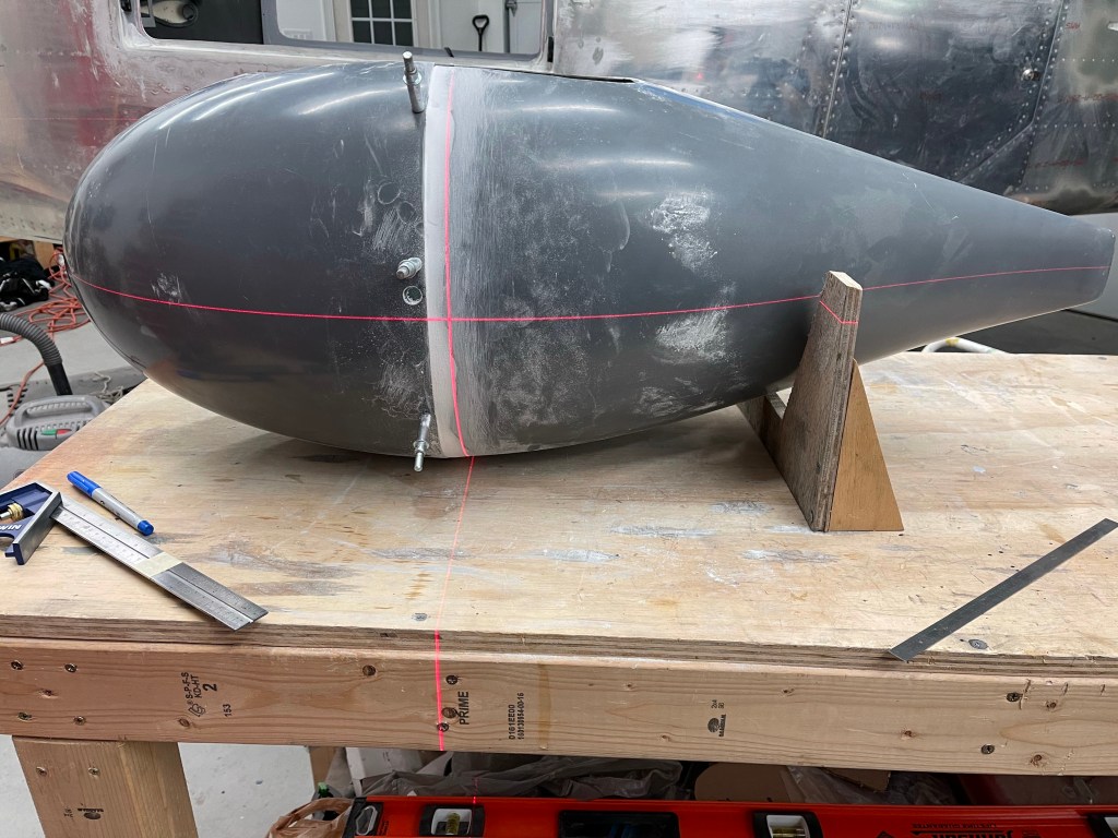
I then used a laser level to mark the center of the bottom cowling to create a cutout for the nose wheel gear leg.
Marking either side of the centerline based on Van’s dimensions for width.
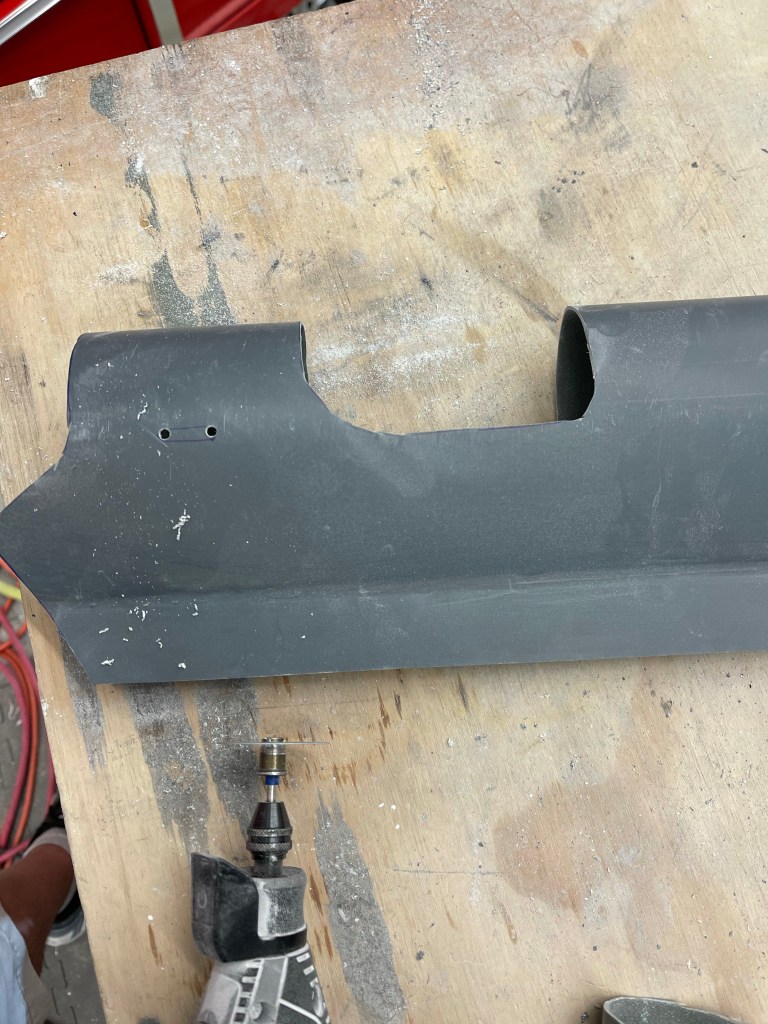
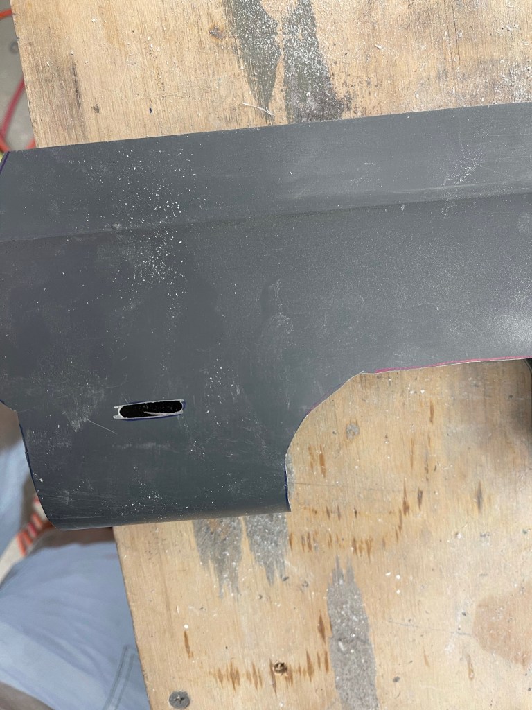
I then used a dremel tool to cut the slot. I estimated the length to cut and then slowly increased 1″ deeper at a time until I was at the bare minimum to get the lower cowling into position. Below is the initial length cut.. I cut a few more inches deeper. My plan is to split this lower cowl into 2 halves to accommodate the 3 bladed prop and I’d like to keep as much original material in this area as possible.
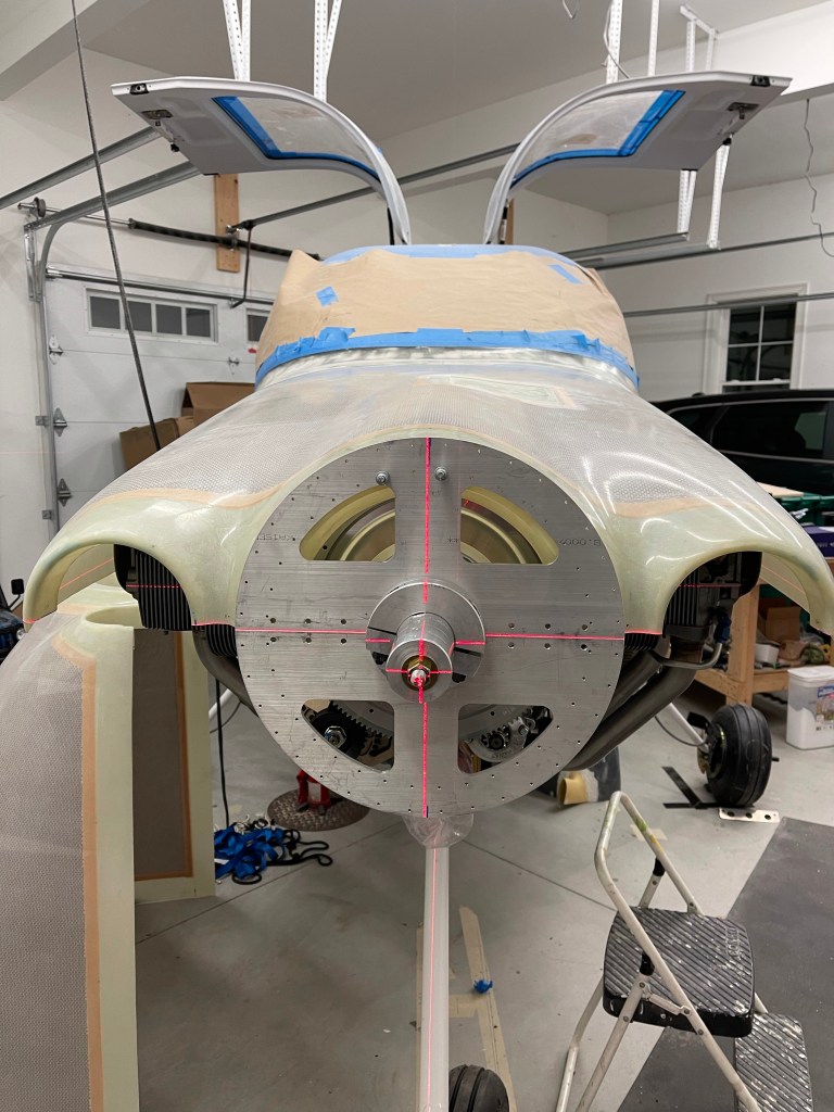
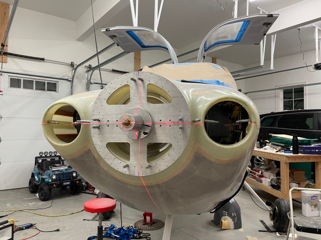
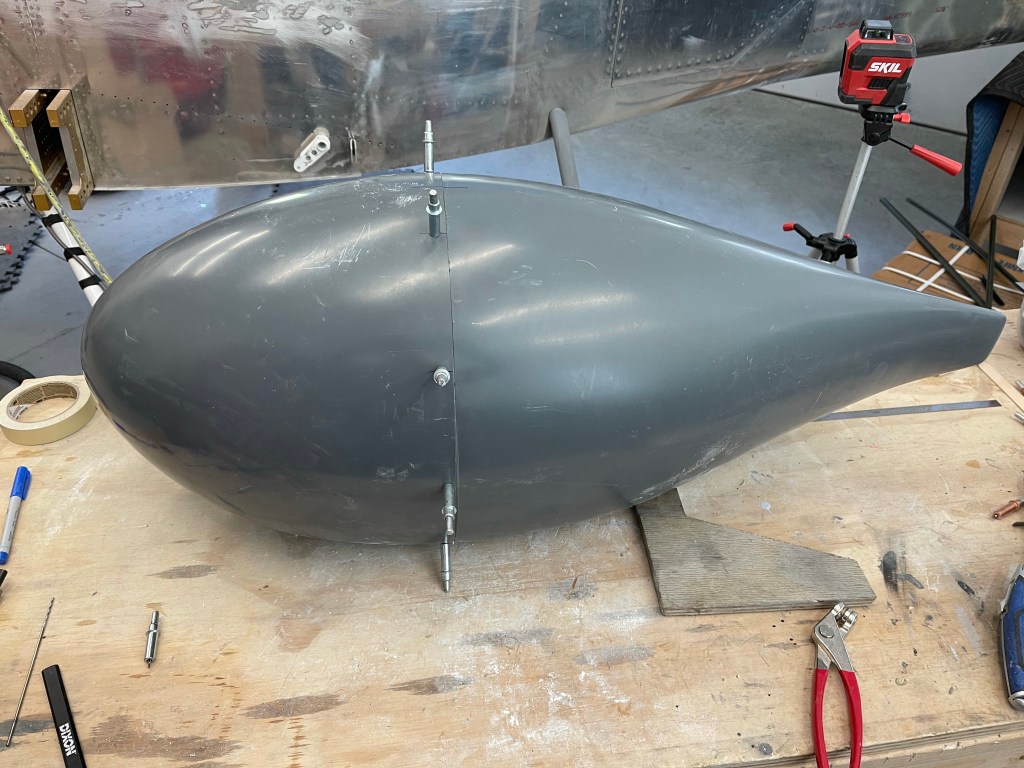
I put the top cowling into position and used a laser level to get it level (after leveling the aircraft) The cowl tool has 3/32″ holes all along the surface to facilitate holding the cowling into place in a fixed location so it doesn’t move during trimming.
Lining up the center line both fore and aft.
With this “extended” hub prop, the cowling sits far enough forward that there is minimal trimming required at the firewall.
Both top and bottom in place
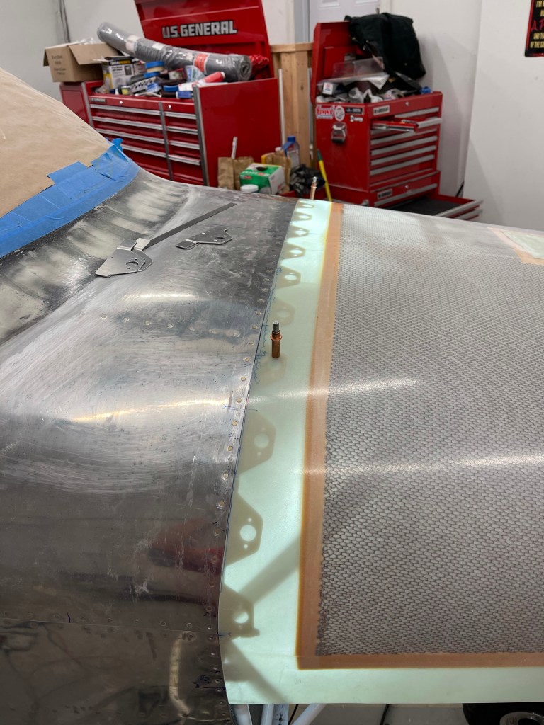
Then starts the task of trimming to the firewall. I used a light on the inside to mark the location of the skin. You then trim 15″ on either side of the center line along the top only. I used a cut off wheel on the dremel tool and left it 2-3mm short.. The 12″ Permagrit sanding block was used for the remainder.. Once this center section is trimmed, the cowl falls down and aft allowing you to get a more accurate trim line for the sides.
Trimming the top center section. All trimmed
I utilized a couple of clecos in the rivet holes of the skybolts to hold the upper cowling in place so it won’t move. I’ll fill these holes in later.
Then starts the task of installing the skybolts and drilling holes in the cowling. I started with a method that I saw Mark use. Using cardboard to drill a hole, I used a small scrap of fiberglass trimmed from the cowl to mock its thickness, and the cleco adapters that came with the kit to mark where the center of the hole was. The cardboard was taped into place so it can be flipped up, the cowl put into place, and flipped back down to drill an accurate hole.
The cowl was then put into place and the hole was drilled.. However, It didn’t really seem to work that well for me. Probably the tolerance of the hole in the cardboard not being perfect.
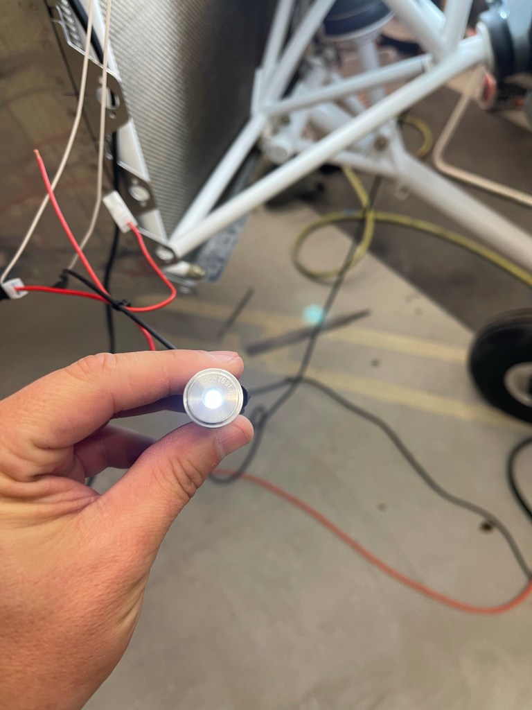
The first Skybolt installed.
What I found was that the light inside the cowling wasn’t direct enough and caused some incorrect alignments when marking the hole and drilling. So I taped a small light into the bottom of the cleco adapter to shine directly on the cowl while it was in position. This was used to drill the remaining holes which were more accurate.
2 or 3 skybolts in place
I then worked one hole at a time from top center downwards towards the sides. Mark and drill the hole to 15/32″, insert the grommet and stud, rivet the receptacle in place, place the cowl back on and test fit the new Skybolt.
Some time back, prior to really needing to order a prop.. I had done a bunch of research on the options.. There’s the stock Hartzell 2 blade metal prop, and various other 2 and 3 bladed props from the likes of Hartzell, MT, and Whirlwind. I put together the following table based on the options I found.
Brand
Model
Cost
Number blades
Blade length
Spinner size
Weight with spinner
Makeup
TBO
MT
PROP MTV12B/193-53
13850
3
76
43
Composite
6 yrs/1800hrs
MT
MTV9
15900
3
76or78
54.9
Composite
6 yrs/2400hrs
Hartzell
PROP C2YR-1BFP/F8068D
9025
2
80
55.6
metal
6 yr/2400 hr
Hartzell
PROP C3Y1R-1N/N7605C SPINNER C-4582-P
20355
3
78
67.5
composite
Whirl Wind
77HRT
12100
2
77
43
Composite
6 yr/800 hr
Whirl Wind
375HRT
14355
3
75
55
Composite
6 yr/800 hr
Whirl Wind
300-77
12500
3
77
42
Composite
6yr/800hr
RV-10 Prop options
While the stock 2 blade is widely regarded as the fastest prop, I felt the 3 blade was a better look for the Showplanes cowling I had already chosen. It also is much smoother and has a shorter blade length giving more clearance there.. Of course that doesn’t go without consequences largely in removing the lower cowling. The plan there is to split the lower cowl into two halves like several others have done. Just more fiberglass work.. 🙂
I saw several of the recent builders go with the Whirlwind 375HRT prop. I had spoken with them and was also planning on going in that direction. The main downside is the lower TBO times, but at about 100 hours per year.. I’d likely hit the same time limit prior to the hours limit, which is the same as the MT and Hartzell.
Fast forward to prop order time, which I had delayed a bit due to the 4-6 week lead times I was consistently given by Whirlwind. Guess what.. They no longer are selling that prop (support only) in favor of their newest 300-77 prop. Which is all fine and everything, but the weight reduction (of all things) was concerning.
Why concerning, you ask? Well weight and balance concerning.. The RV-10’s CG moves aft as you burn gas.. Ideally, you’d like to have your empty weight as close to the forward CG limit as possible so as to allow for max carrying capability and gas burn as you go longer distances, even if that means throwing in some ballast when solo. Having a prop that is over 10 lbs lighter out front combined with my Air Conditioning (mostly CG neutral, but ever so slightly aft), an O2 bottle, and a standard technology battery (read heavy) behind the baggage bulkhead, I was concerned.
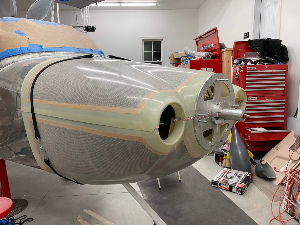
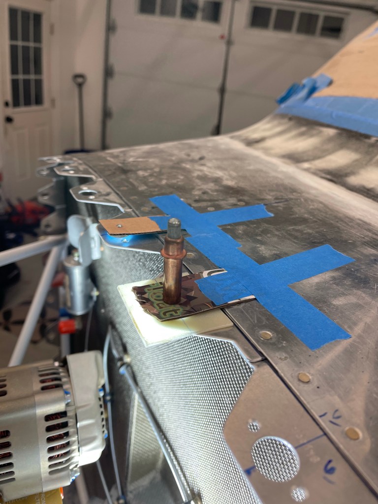
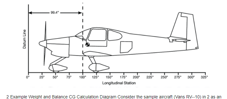
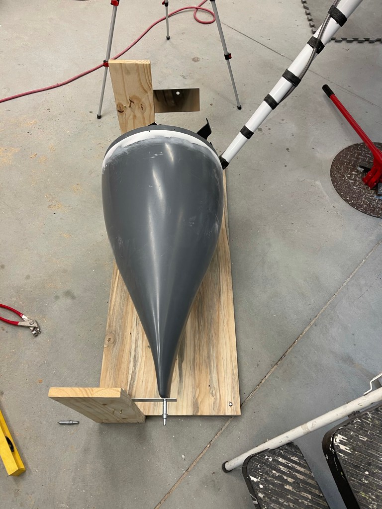
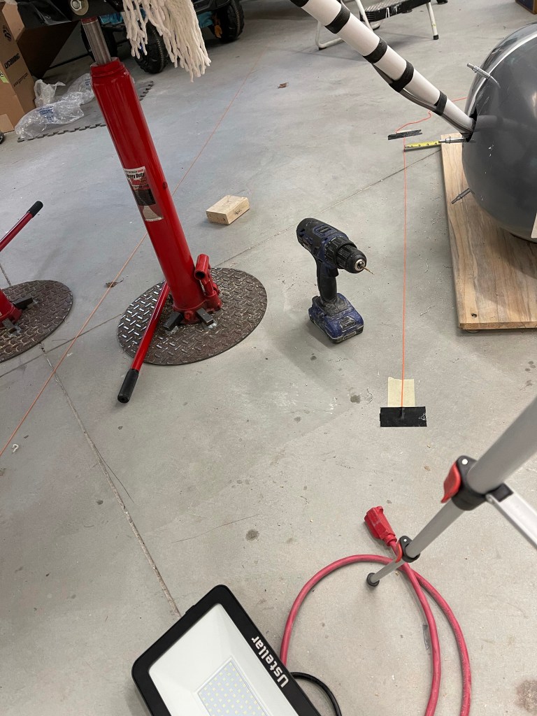
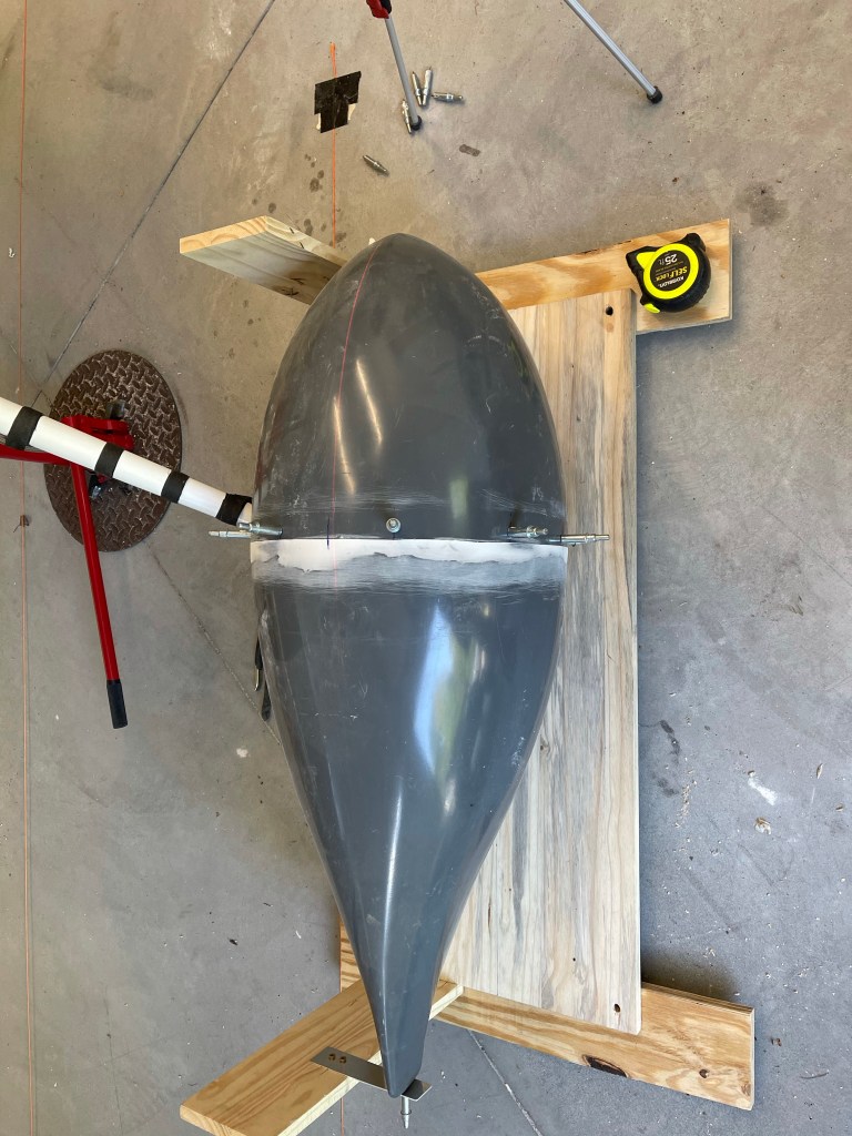
It’s difficult to know exactly what my empty weight will be, but I grabbed 2-3 samples of what I could find and was provided by other builders. I did a bunch of playing with W&B by estimating the arm of the prop (approx at the hub) at 32.7″ from this picture:
I did that by measuring the scale with a ruler between 25″ and 50″ and then calculating the number of inches per 1/32″ and figuring out the distance to add to 25″ to get to a line drawn through the prop location.. I felt that was good enough for my comparison purposes..
I then found an example W&B spreadsheet online that had lots of weight scenarios listed for that given plane. I modified the spreadsheet to subtract out the weight of the prop that plane had on it and added back in the WhirlWind Prop weight. Here is the stock aircraft examples of empty and gross weight.
AIRCRAFT EMPTY
Location
ARM
WEIGHT (LB)
WEIGHT (KG)
MOMENT
Left Main Wheel
124.31
621
282.27
77197
Right Main Wheel
124.44
608
276.36
75660
Nose Wheel
50.44
328
149.09
16544
Main Fuel Tanks
0
gallons
108.9
0
Pilot
114.58
0
Copilot
114.58
0
Passenger
151.26
0
Passenger
151.26
0
Baggage
173.5
0
Survival Gear
173.5
0
Remove stock prop
32.7
0
0
Add WW Prop
32.7
0
0
Totals
1557
708
169400
C of G Location
108.799
Forward Limit
107.80
Aft Limit
116.24
AIRCRAFT AT GROSS
Location
ARM
WEIGHT (LB)
WEIGHT (KG)
MOMENT
Left Main Wheel
124.31
621
282.27
77197
Right Main Wheel
124.44
608
276.36
75660
Nose Wheel
50.44
328
149.09
16544
Main Fuel Tanks
60
gallons
108.9
360
39204
Pilot
114.58
186
80.00
21312
Copilot
114.58
176
80.00
20166
Passenger
151.26
176
80.00
26622
Passenger
151.26
176
80.00
26622
Baggage
173.5
59
10237
Survival Gear
173.5
10
1735
Remove stock prop
32.7
0
0
Add WW Prop
32.7
0
0
Totals
2700
1028
315297
C of G Location
116.777
Forward Limit
107.80
Aft Limit
116.24
So about 1″ aft of forward limit empty and slightly out of CG aft loaded up with full fuel and passenger weight somewhat equally spread around.
Now comes the effect of doing the prop swap:
AIRCRAFT EMPTY
Location
ARM
WEIGHT (LB)
WEIGHT (KG)
MOMENT
Left Main Wheel
124.31
621
282.27
77197
Right Main Wheel
124.44
608
276.36
75660
Nose Wheel
50.44
328
149.09
16544
Main Fuel Tanks
0
gallons
108.9
0
Pilot
114.58
0
Copilot
114.58
0
Passenger
151.26
0
Passenger
151.26
0
Baggage
173.5
0
Survival Gear
173.5
0
Remove stock prop
32.7
-55.6
-1818
Add WW Prop
32.7
42
1373
Totals
1543
708
168956
C of G Location
109.470
Forward Limit
107.80
Aft Limit
116.24
AIRCRAFT AT GROSS
Location
ARM
WEIGHT (LB)
WEIGHT (KG)
MOMENT
Left Main Wheel
124.31
621
282.27
77197
Right Main Wheel
124.44
608
276.36
75660
Nose Wheel
50.44
328
149.09
16544
Main Fuel Tanks
60
gallons
108.9
360
39204
Pilot
114.58
186
80.00
21312
Copilot
114.58
176
80.00
20166
Passenger
151.26
176
80.00
26622
Passenger
151.26
176
80.00
26622
Baggage
173.5
59
10237
Survival Gear
173.5
10
1735
Remove stock prop
32.7
-55.6
-1818
Add WW Prop
32.7
42
1373
Totals
2686
1028
314853
C of G Location
117.202
Forward Limit
107.80
Aft Limit
116.24
Note that empty, it moved the CG aft by 0.671″ and by 0.426″ in the gross case.
I, of course, ran a bunch of other configs including our Family profile (Assuming Declan fully grown) and it would all be okay.. but low on fuel you can actually get slightly aft of the limit with lighter prop. All would be fine with the weight of the standard prop. I won’t bore you with several tabs of spreadsheet data I played with here.. 🙂
All of this further reinforced the need to find a prop that was close to the stock 2 bladed prop for piece of mind. That left me with 2 choices.. Hartzell 3 blade (super expensive) or the MT MTV-9 prop..
There were a couple of other builders that have used this prop. Van’s typically recommends the MTV-12. One of the main reasons they used it was the max HP rating of the MTV-12 is around 300HP, and they had similar engines to me.. meaning cylinders ported and polished, cold air induction, and higher compression ratios.. MT suggests the MTV-9 for these applications as it can handle significantly more HP (thus the extra weight). In addition MT says that there is no issue using electronic ignition with this prop at my approx HP. (they didn’t support doing that with the MTV-12, even though I know others have done it). So all of that plus the weight that is very close to the Stock 2-blade and I decided to go with it. I placed an order for the MTV-9-B/198/52 with nickel leading edges in a matte black with white tips configuration. They also suggested this spinner, which I passed by Bryan at Showplanes, and he thought it would work fine.
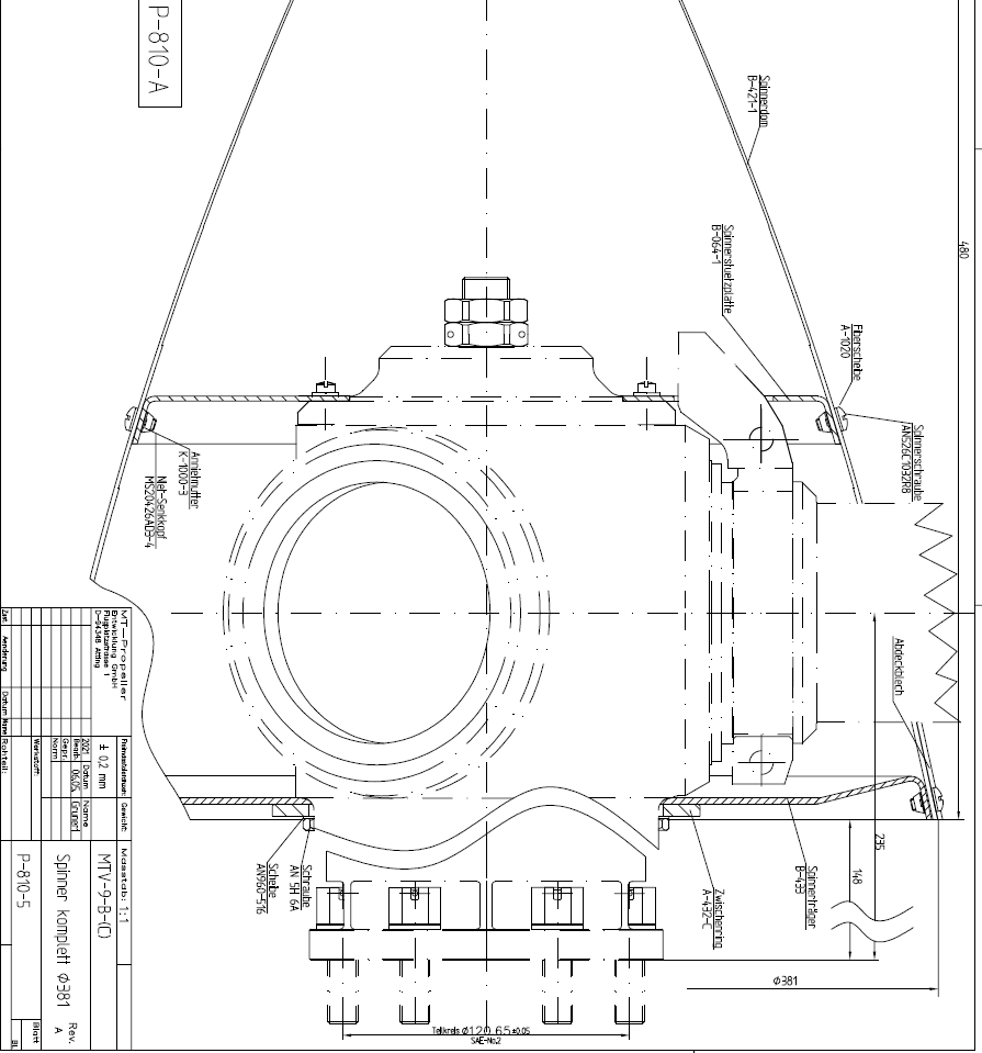
P-810-5 Spinner.
The issue came with the 148mm prop flange to aft spinner dimension, which I was asked about and didn’t think it would be an issue. Especially seeing Bryan said it would be okay and I know other RV-10 builders that have used this prop.
Until it was an issue..
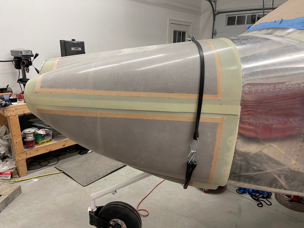
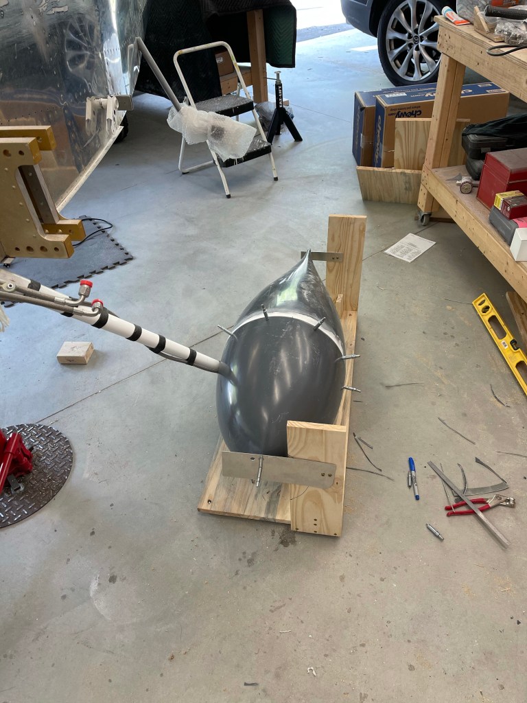
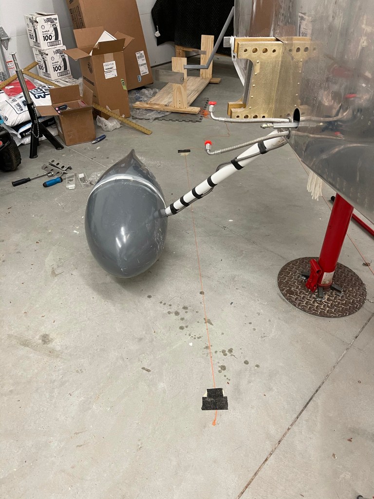
I bought the cowl installation tool from Flyboy accessories to place the cowl ahead of getting the prop. It is well designed and provides an adjustable 15″ wheel that serves to set the cowl back from the spinner assembly.
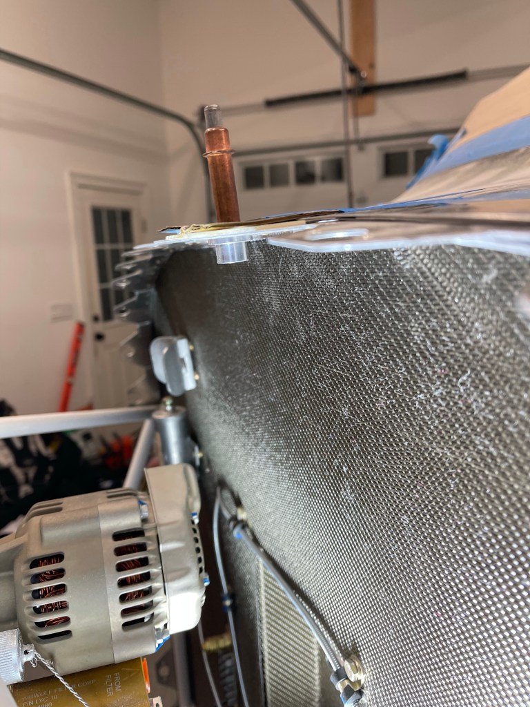
I set the spacing to 148mm minus about a 1/4″ gap. Placed the upper cowl in position.
And DoH! the cowling is so far forward it doesn’t even reach the firewall.
I contacted my MT guy and described the issue and to see if they might have any other spinner/hub setups that might work better for me. In the meantime I mulled over what to do.. I had heard of another builder using the Hartzell 3 bladed prop with an I-hub config which pushes the spacing out enough to fit the AC compressor without having to cut and bump out the cowling. I got some info on that as an option.. I also contemplated what would happen if I cancelled my MT order.. Either lose some/all deposit money or continue with the purchase and try to sell it..
MT got back to me with a spinner specification sheet. I used the info I got about the Hartzell I hub spacing and did some mock ups and measuring.. I ended up getting a range of prop flange to aft spinner measurements that matched the Hartzell I hub design at the minimum side and a measurement as far forward as possible with almost no cowling overlap onto the firewall at the max side. I filled out their form and asked if there was anything off the shelf that would work.. I came up with somewhere between 69.3mm and 82mm would work for me.
A couple of days later engineering came back with this .. A P-810-3 spinner with 75mm spacing. It’ll work!!! What a relief..
P-810-3 Spinner
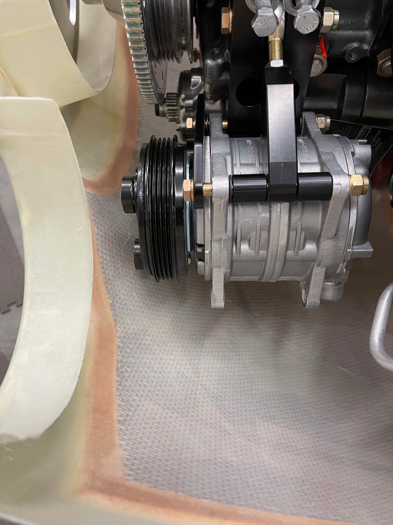
I mocked this distance up and checked the spacing of the AC compressor up front with the lower cowl roughly in place.. There is plenty of room to not have to do any lower cowl modifications for the compressor. Win win!
I told MT that it would work. A change order was put in with no anticipated delays seeing I’m still far enough out in production. I’ve been able to continue forward with the cowling install now that the spacing is known.
I will say that I’ve encountered a bunch of negativity about MT and using their props along my research. While I agree that might become true with months of delays in the case of something catastrophic that needs to go back to Germany to get fixed. For most run of the mill things it shouldn’t ever be an issue (at least I hope not). The local guys are easy to work with and bend over backwards to make things right. I also have a certified MT service shop relatively nearby in CT that I could drive to if need be. Thus far, I’m impressed with MT.
Sorry for the long post… it’s been a few months in the making.
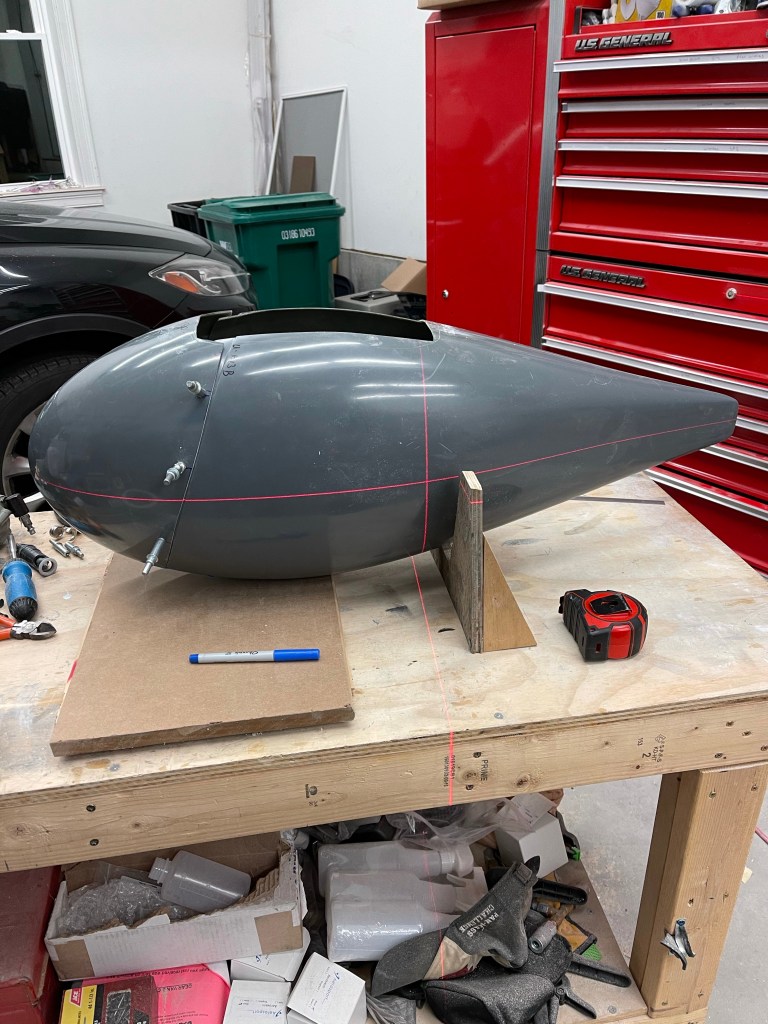
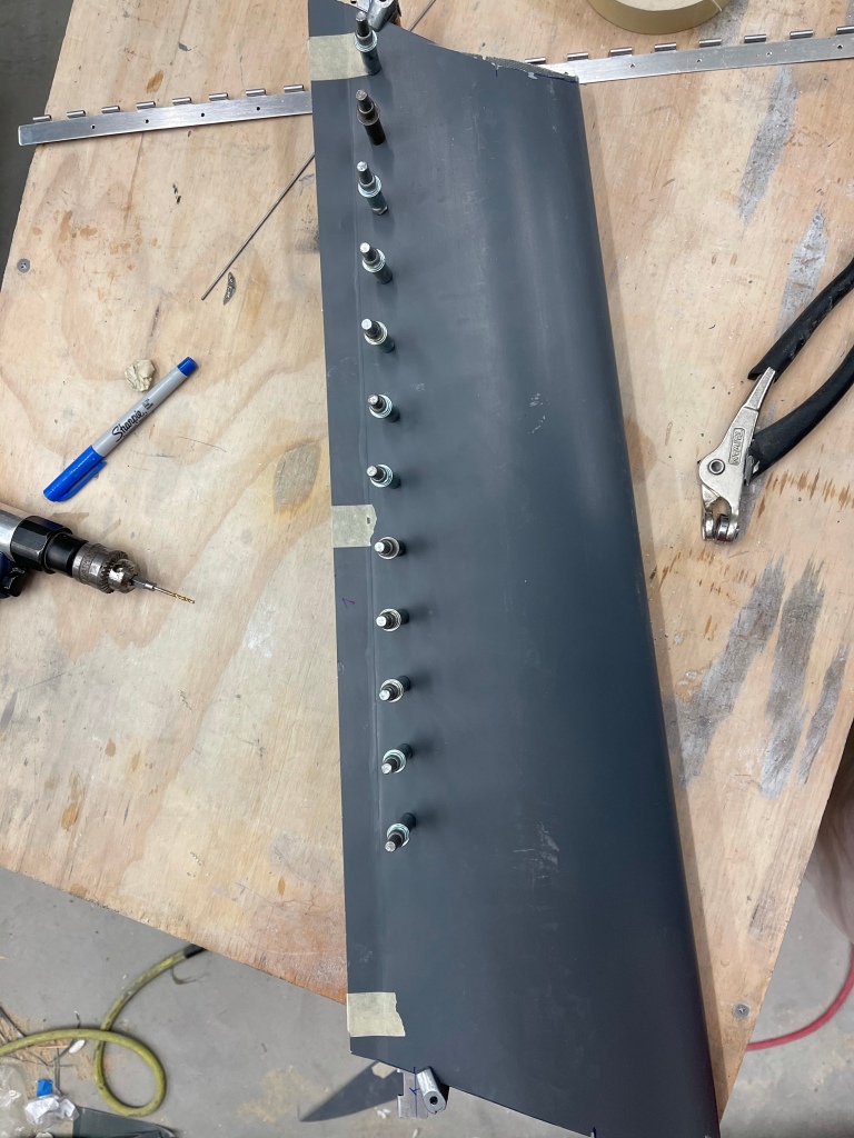
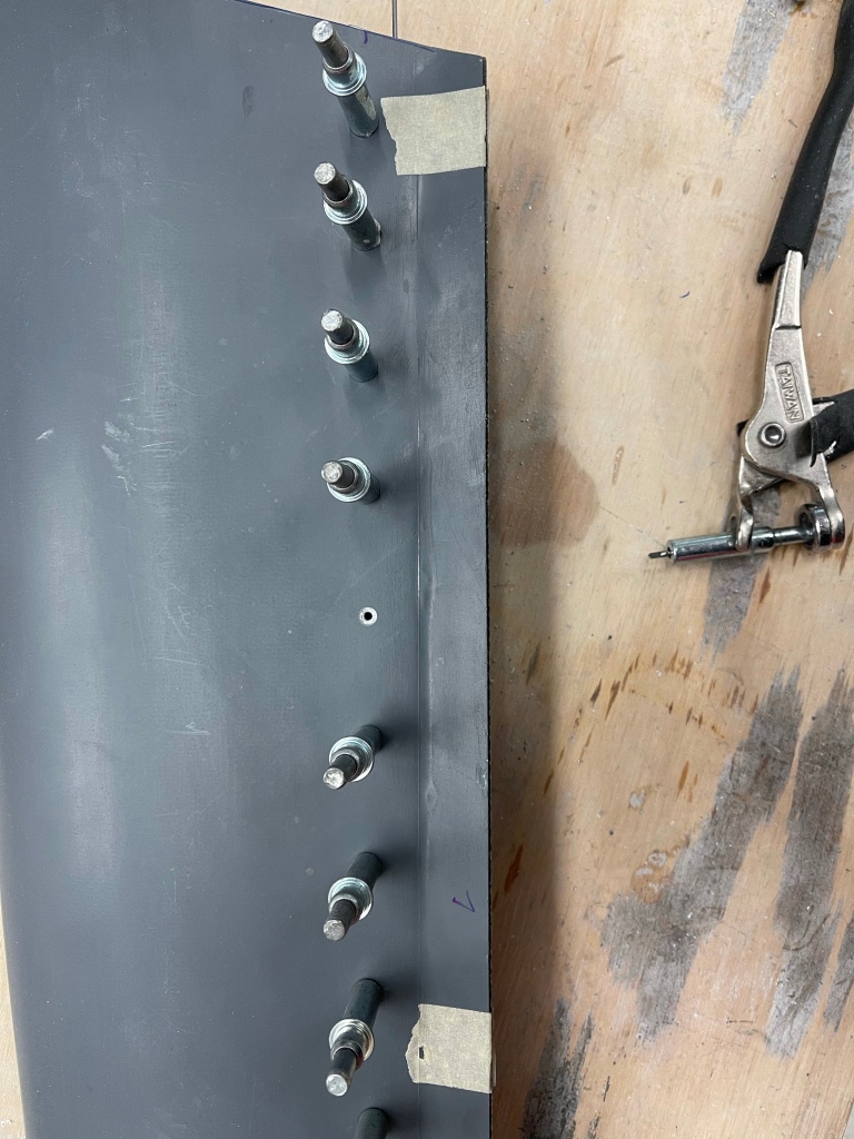
This section is very similar to the main gear fairings in that you find the center point of the aft point of the fairing, extend this centerline to the front of the rear pant, then put the 2 halves together and drill #40 holes along the flange at the specified distances. I used a piece of tape with the distances marked out and taped it along the fairings to mark the drill locations. You then use the same “V” wedge that was used on the main gear to help prop the fairing up so the height of the aft center point is a specific distance above the table. This measurement was then transfered to the front using a laser level and double checking with a square.
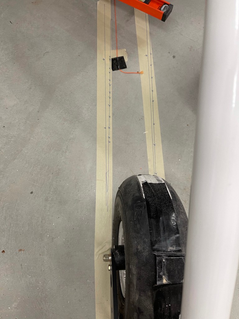
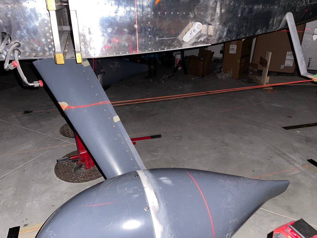
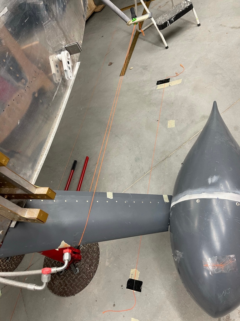
It’s then time to start working on fitting the faring to the nosewheel. One thing that I did that wasn’t outlined in the plans was to mark the location of the nose fork on both sides and extend those line rearward.. As you can tell by the tape and multiple lines, this did take a couple of iterations to get right. I ended up using a laser level to mark them after aligning the beam with the forks. A wooden spacer is also taped to the top of the tire.
I then marked the center point between the 2 extended nose fork lines and used that location, along with my laser level to make sure that the fairing was always inline with the tire. I’ve still got the plane up on jacks and there is no weight on the front tire, but it’s on the ground enough to not allow it to swivel.. So this mark shouldn’t change as I proceed.
Aligning the faring to the centerline of the nose wheel.
I reused the “V” wedge that I had made and repurposed it to hold the center point of the fairing at the proper height from the floor. Very similar to the jig I used for the main gear. Later, I will cut the V wedge in half and use it on both the front and aft holes of the fairing.
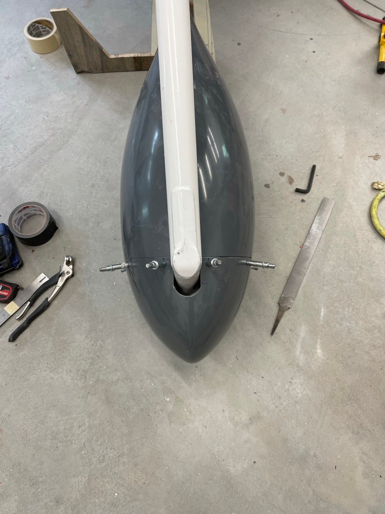
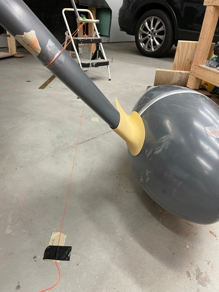
I then followed the plans to drill a 1.5″ hole into the front fairing and trim the tangent lines to allow clearance for the nose gear leg. Once that was done, I was able to file a little bit more along the edges and get the front re-cleco’ed to the rear.
Front fairing mated up with rear fairing
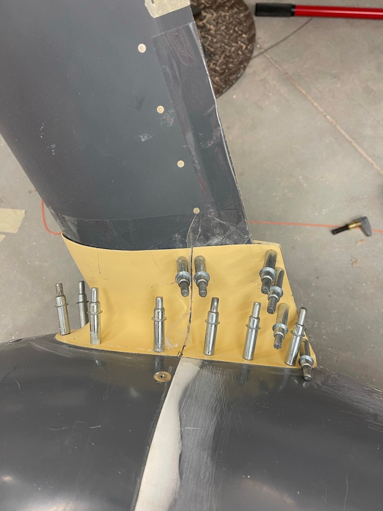
Then after making sure the front and aft locations of the fairing were at the proper height from the floor, you move on to drilling the screw holes into the fairings for the fairing brackets. These ones seemed to be more of a pain compared to the main gear as I had a hard time getting a light from the inside to cast a shadow that I could see on the opaque fairing.
Fairing bracket holes drilled (on left side)
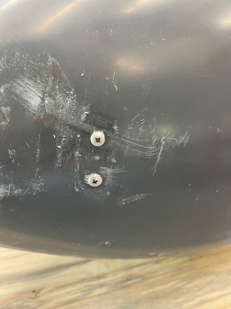
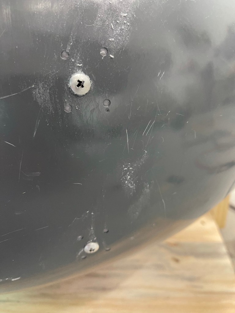
Once again you repeat the main gear procedures for squirting a flox/cabo mixture around the fairing brackets and screws to build up the area inside. I, once again, drilled small holes around the perimeter of the screw hole and used a syringe to squirt in the mixture. Below is a shot of the fairing bracket screwed into place and the hole drilled for a nose-wheel tug to connect onto the bolt location.
Fairing bracket screwed into place. Outside look at the fairing.
The 2 halves are then joined using screws after final drilling, countersinking, and installing nutplates.
Nosewheel in place all screwed togetherCloseup of the tug access hole to the nosewheel bolt.
I also decided to use these metal tug guards https://www.flyboyaccessories.com/product-p/73301.htm I recently saw come up for sale. This will help protect the fiberglass fairing and the paint job from getting all dinged up when trying to connect and disconnect a tug/towbar. Might as well install them now while I’m working on these fairings. These were matched drilled to the supplied backing plate. All that’s left now is to countersink, spread some flox/cabo on the backing plate and rivet them in place.
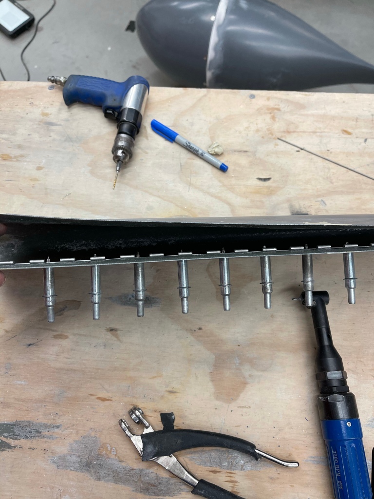
I then set out to get the nosewheel gear fairing going. These are also similar to the main gear leg fairings. A template is used to cut the fore and aft edges and also the U shaped cutout . Here you see me cutting away a slot for a hose clamp by first drilling 2 holes and then removing the material between the holes on the tangent lines.
Start by drilling holes at the ends. Then remove the material between the holes.
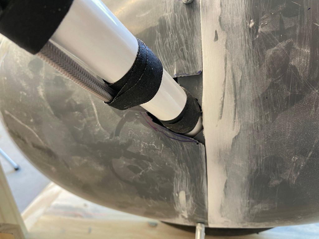
The fairing was then put into position. Some additional trimming was needed at the interface to the nosewheel fairing, and some more still needs to be done, but this is close enough to start on the hinge along the aft edge.
Test fit of leg fairing. Pretty close trim.. still needs some more trimming/sanding to allow nosewheel to caster around it.
I’ll need to final trim this after I take the plane off of the jacks, as I’m not able to swivel the nosewheel just yet without worrying about the plane falling off the jacks.
As I previously mentioned, a result of splitting the lower intersection fairings and bonding them to the wheel pants has some implications. It’s important to not allow airflow to get underneath the rear fairing half. If that were to happen, it would rip it right off the airplane. So I took some scrap material from cutting the gear leg fairings to use as a flange for the rear half. I cut about a 1″ piece and let approx. 3/8″ of a flange protrude. On a couple of the curved areas, I used a heat gun to contour it to the intersection fairing.
Flange in place
Below you can see both flanges in place and taped up so that no epoxy sticks to them.
I then laid up several layers of fiberglass cloth over the flange and attaching to the forward intersection fairing. This essentially will create a :”tab” for the flange to mate to and keep both the forward and aft sections together.
Another angle of the fiberglass layup. Curing.
Once that was cured, I separated the two halves and permanently bonded the flanges in place with flox and cabo.
Flanges bonded in place.
A couple of shots of the resultant tab that the flange sits in (prior to any trimming.)
This should provide a solid interface between the forward and aft intersection fairings at the split.
I didn’t take any pictures of the start of this process, but you basically cut a paper template out of the plans and tape it to the fairings as instructed to mark and make the top and bottom cuts that align to the bottom of the fuselage and the wheel pant. I then placed them on the gear legs to test the fit.
Pretty good initial cut against the wheel pant.
You then cut the piano hinge to length and start marking where it will go to hold the trailing edge together. One slight deviation from the plans was to mark out the drill holes on the hinge and actually drill them with a 3/32″ drill ahead of time. The plans want you to drill through from the outside, but that goes back to the times when these fairings weren’t gel coated and were transparent. I then used the undersized holes in the hinge to match drill #40 into the fairing from the inside with a right angle drill.
First hinge mostly match drilledRight angle drill used from the inside to match drill the hingeCountersinking for flush rivets
You then re-install the leg fairings and insert the hinge pin, which is sort of a PITA. Once that task was over, the plans walk you through how to align the fairings properly. Getting this wrong can cause yaw, so you want them as perfectly aligned as you can. The plans have you wrap a string around the leg faring and clamp it to the step. I also feel that that plans walk you through placing a displaced centerline mark at a random location.. I basically reused the string I already had on the floor from the wheel pant install. The issue I ran into was my location.. and just some random location, as mentioned in the plans, isn’t the correct location when the string is perfectly level. So my advice would be to level the string, then use a plumb bob to mark the forward location of the string on the floor. Then duplicate the measurement from the airplane center line behind the step. Place the string that is the displaced centerline of the aircraft and use a plum bob to transfer the location to the step. You then move the aft part of the string to this mark on the step so the string ends up both level and parallel to the aircraft centerline.
Getting the string in placeUsing a laser level to verify the string is perfectly level.End result of the string level and parallel to the Center Line
You then adjust the rotation of the fairing until there is an equal distance between the trailing edge of the fairing and each side of the string.
Proper alignment.
To lock this positioning in place, you move on to install the intersection fairings. I used the intersection fairings from RVBits instead of the stock ones, which need lots more work. The lower left fairing was slid on using care to not change the alignment, which of course was re-checked multiple times.
Lower intersection fairing in place. Front view.
I’ve decided to bond the lower intersection fairings directly to the wheel pant instead of using more screws to hold them in place. Doing this will require cutting these intersection fairings where the wheel pants separate from each other. It will also require me to add a flange onto the rear pieces so they stay locked in place under the front pieces with no way to get airflow under them.
I drilled a bunch of holes in prep to bond the 2 surfaces together.
The below picture was taken after I started taking clecos out, but I used a laser level to mark the fairing at the wheel pant split. I also decided to add a couple of additional clecos up at the top of the intersection fairing on either side of the cut. I did the same thing for the inside line as well (not visible here).
Cut line marked.
I then took things apart, cut the intersection fairing taped up the leg fairing so things wouldn’t stick together, and mixed up an epoxy/flox/cabo mixture putting things back together and letting them cure overnight.
All put back together and curing overnight.
The next morning I took the wheel pants off and the separation of the intersection fairings worked out well as shown below..
Rear fairing.Front fairing.
A couple of pictures of the wheel pant put back together.
I then placed and drilled a small hole for clecos (for now) and placed the upper intersection fairing into position. This will later also attach to the wing root area.
With the jig leveled off and touching the bottom of the tire, the rear of the gear pant was put into place to trim a small amount to accommodate the gear leg. You continue trimming until the gear fairing extension hole is coincident with the aft “step” of the flange on the pant. then just make sure that you have some small gap all the way around the gear leg.
Rear pant in place
Then the same thing is done with the front pant. Trimming until you can fit it on the rear and have a small gap around the gear leg itself. One thing I did a little different on the right side (the 2nd one I worked on) was to mark out the extended centerline sooner and have the alignment of the pant at least close to where it needs to end up. On the left, I was slightly off and ended up trimming more than I should have. Nothing that the intersection fairing won’t cover up, but still a little too much. The plans don’t really have you aligning things to the centerline until after the trimming is done..
Front joined to rear to start the alignment.
I then dropped a plumb bob on the centerline of the plane and marked it with a string.
Aircraft centerline
I then took a square and measured a random distance over that would provide a good displaced centerline reference closer to the pant/jig itself. I also used a string to mark this on the floor.
Displaced centerline reference
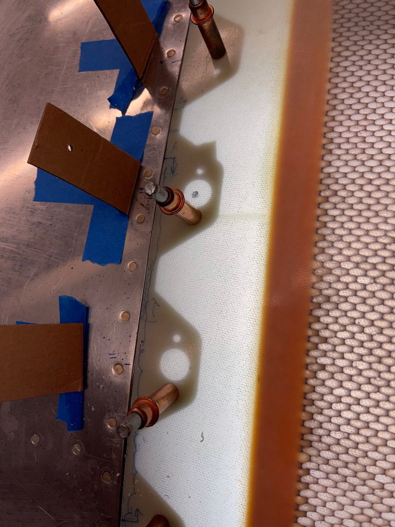
The jig and pant combo was then aligned to the centerline by marking the centerline of the pant in the jig and making sure the measurements from the displaced centerline to the jig centerline matched as perfectly as possible front to back. It’s then that you drill the holes through the pants lining up with the holes in the fairing brackets. This is done by shining a light on the inside so you can see the outline of the hole against the gel-coated fiberglass surface. Once those holes are done and oblonged as needed to align things perfectly.. The area on the inside of the pant, where the screw goes through and mates with the fairing bracket needs to be beefed up with flox. This was done by drilling several small holes around the screw and squirting the epoxy/flox/cabo mixture into them with a syringe.
Closeup of rear screw locations while flox was curingCloseup of front locations of the screws into the wheel fairing brackets. Everything all aligned.
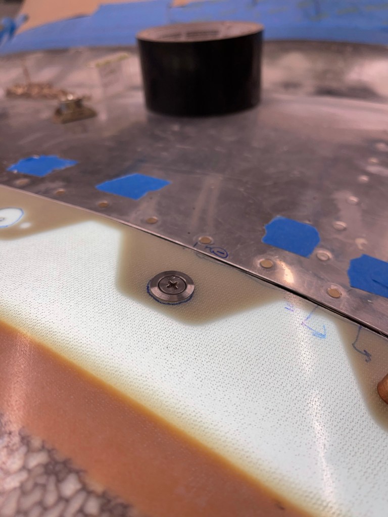
You then also beef up the area where the gear extension is with a flox/cabo mixture. After that cures, you take the pants apart and place nut plates for #6 screws where the cleco holes were.
Most of the screws are in place here.
All of the same things were repeated on the right side. Below are some better pics of the trimming reliefs for the gear leg.
Right pant all aligned. Right pant done too. Both main wheel pants done!
Another task to do before the engine arrives and gets hung is to install the wheel pants and leg fairings. This step requires you to jack the plane up to get the weight off the wheels. I’d like to get this step done now before the plane bulks up another approx. 400lbs. Otherwise I’d likely end up waiting until the wings are on and jacking it up by the tiedown locations, which means I’d probably procrastinate and have to do this after I’m flying.
You start the wheel pants by sanding the two halves of the pants where they are built up to make them fit together well. The plans then have you trim/sand the front flange as required to get a square fit. This was accomplished by running a sharpie around the circumference of the pant on a flat table. I then trimmed to that line.
Marking the trim line
The next steps have you find the vertical and horizontal center of the aft end of the pant. The use of a laser level helps here.
You then mark the locations to drill holes to mate the two parts as called out in the plans. I used a piece of tape with the various measurements needed to accomplish this paying attention to left vs right as the dimension are different on each side and are mirror images of each other.
Tape with measurements to mark hole locationsAll holes drilled and held together with clecos
The next task is to mark the equivalent horizontal mid point on the front of the wheel pant. You use a wooden fixture to help hold the pant into position while making sure the aft end is at the plans specified height. Also making sure to make sure everything is plumb and square.
Aft end at proper height
Again a laser level makes easy work to transcribe this line to the front of the pant. I used the square with the tape mark on it to double check that is was correct.
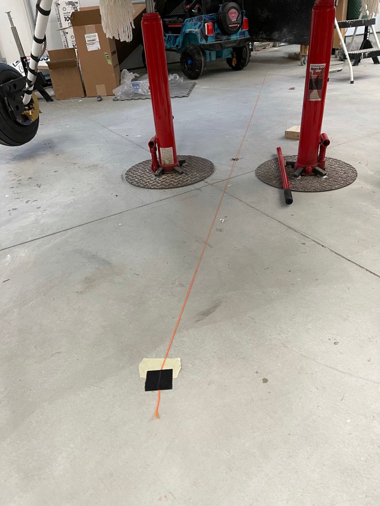
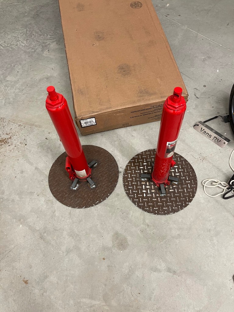
Now comes the point where you need to jack up the plane. The plan is to place jacks under the main wing spar on either side of the plane and jack up the plane. Then you must make sure that the plane is in flight level attitude as described in the plans. Levels were used to confirm this. I had some adjustable screw-style jacks that I had planned to use for this, but what I found out is that the adjustable height nature of them made for too much wobble side to side, which made me very uncomfortable. The one thing you do need to make sure of is that you’re careful when jacking this thing up entirely off the ground. It can easily fall off the jacks and cause damage or worse injury… So I decided to go buy better jacks that I’ve seen many people use from Harbor Freight and have a local guy weld some bases on so they won’t tip over. I will most likely be using these on at least an annual basis during condition inspections to lift the plane up, so the investment is not wasted.
Jacks with welded bases on.
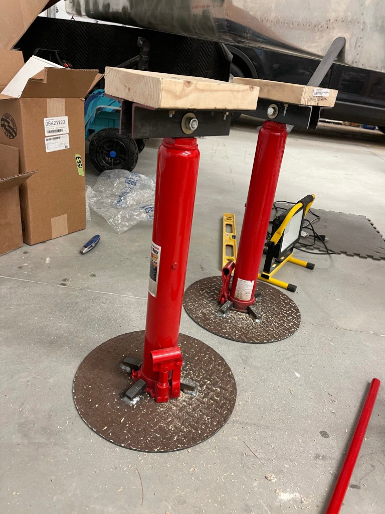
I then used some steel angle I picked up at the hardware store and a length of 2×6. I make 1/2″ holes on one side to go through the large hole at the top of the jack and a couple of holes to attach the 2×6 to the angle with a couple of bolts per side. I then added padding to the 2×6’s and the end result was much more stable.
Finished Jacks minus paddingPlane up on jacks in flight level attitude.Also note the wooden jig in place for test fitting
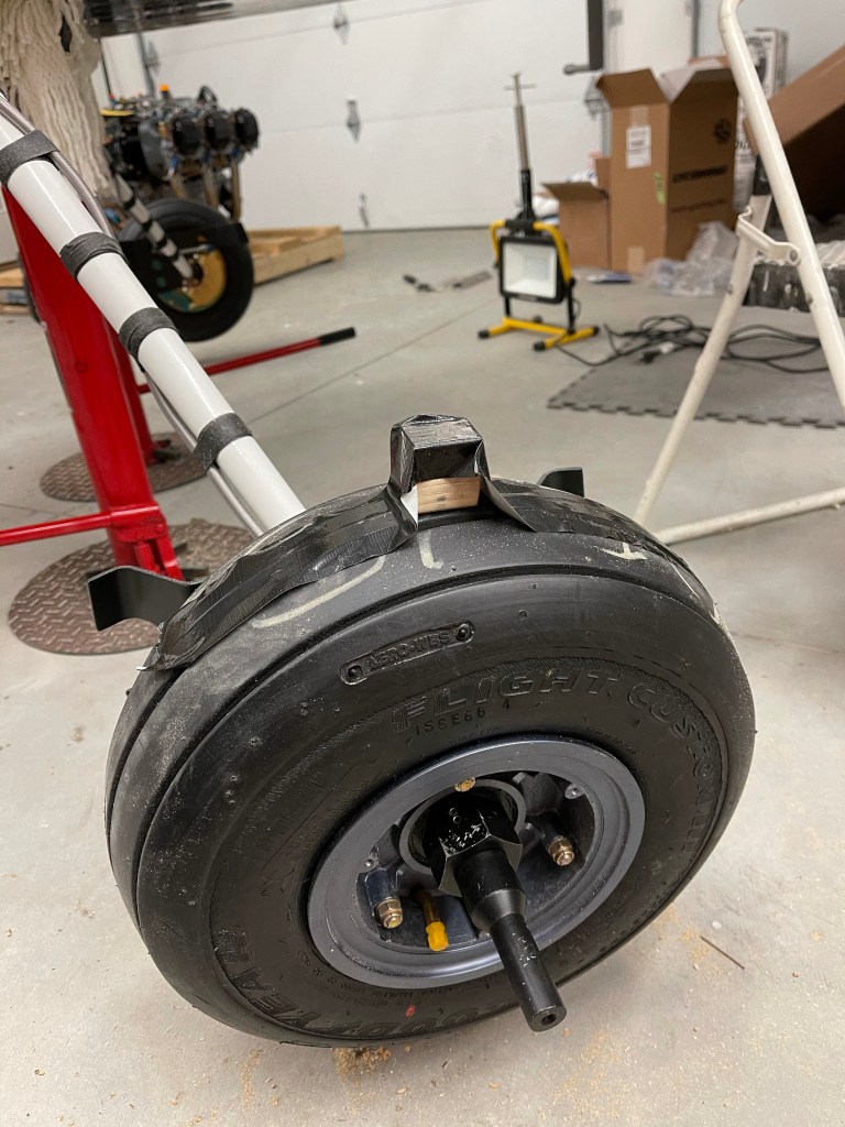
I then worked on making a jig to hold the pants into position for me as I’ve seen others do. This will help hold the pant perfectly in place the correct distance to the “floor”, which becomes the top surface of the jig. In each corner there are adjustable feet so I can get things perfectly level.
1 1/4″ spacer taped to the top of the wheelSetting the proper height above the floor (jig) for each end of the pant.
Up next is to start drilling holes and getting the pants properly lined up on the wheel assembly itself.
Couple of small things to finalize about the gear installation prior to moving on to getting the interior panels trimmed.
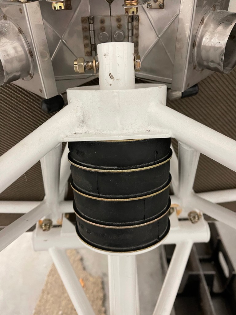
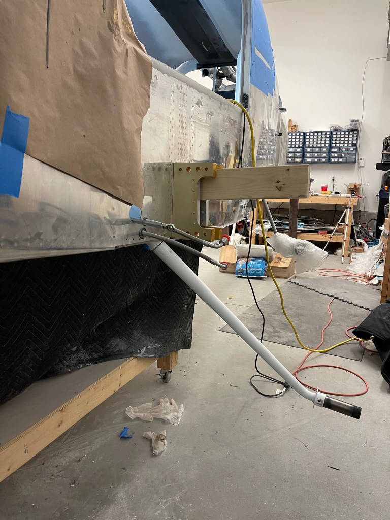
First was to tackle the hardest bolt in the airplane to install. The bolt that holds down the nose gear donuts. This thing requires a lot of compression to even get the bolt hole to line up. Luckily, I have a tractor. So I strapped the engine mount to my bucket and let the hydraulics do the work. Even still, the bolt was stubborn. I feel for others who have said they’ve had family members hanging off the engine mount while someone pushed the tail upwards while trying to muscle that bolt in place.
Tractorcomes in handy!Hardest bolt installed!
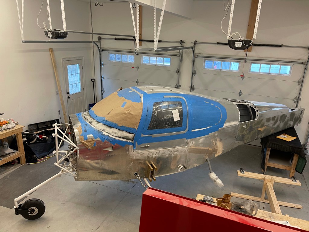
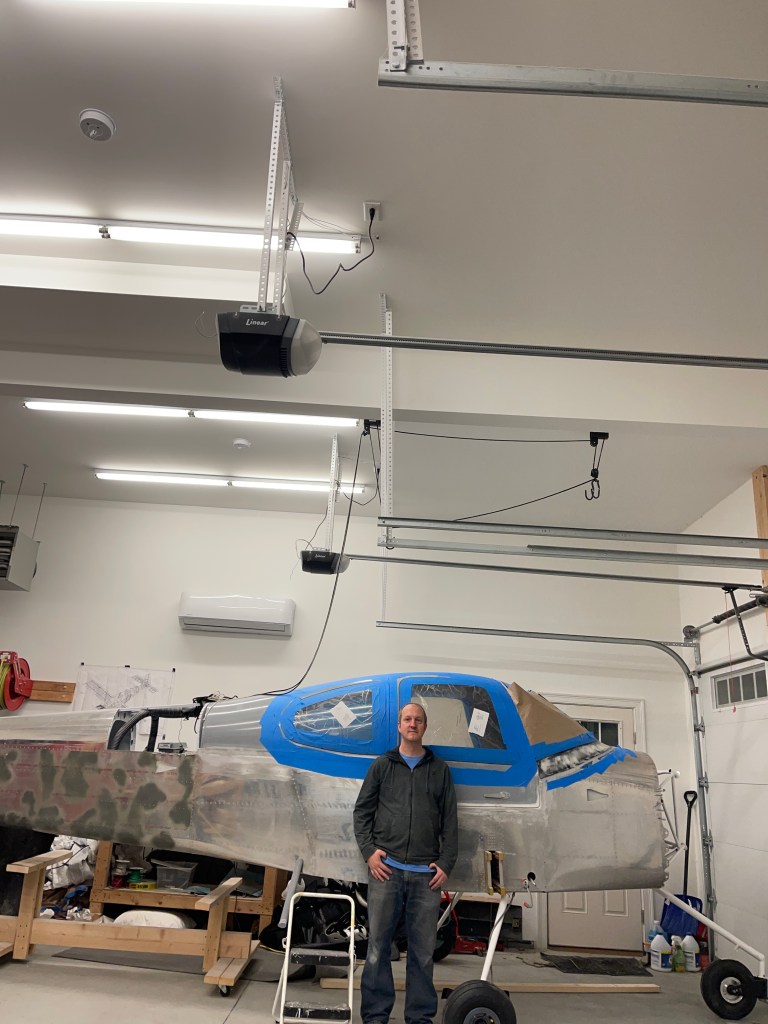
I then got the plane repositioned in my garage. It’s now kiddie cornered across 2 stalls so I have room for the engine to be mounted and still move around it.
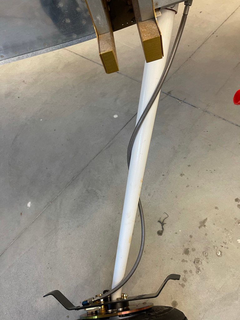
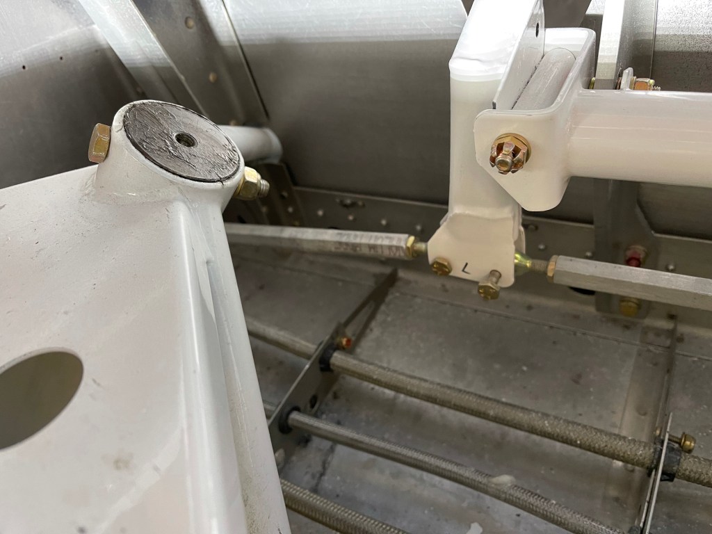
I also got the brake lines installed and taped to the gear legs.
Brake lines taped
While I’m waiting for my engine to arrive, I’m knocking off misc items still to do on my list.
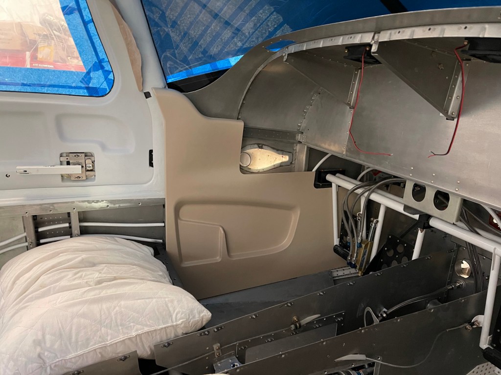
I started getting the interior side panels trimmed to be able to paint them. I started with the rear panels as they don’t require too much trimming. I did have some adjustments to do as I did build up the door areas a little more than stock, but the trimming wasn’t too bad.
Left rear and baggage door panels Right rear panels
There are 4-5 screws that need to be located and nut plates added to hold the panels in place.
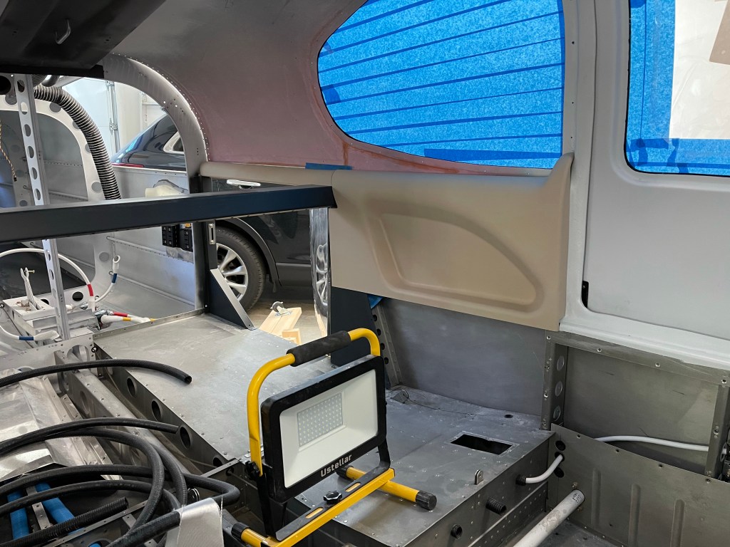
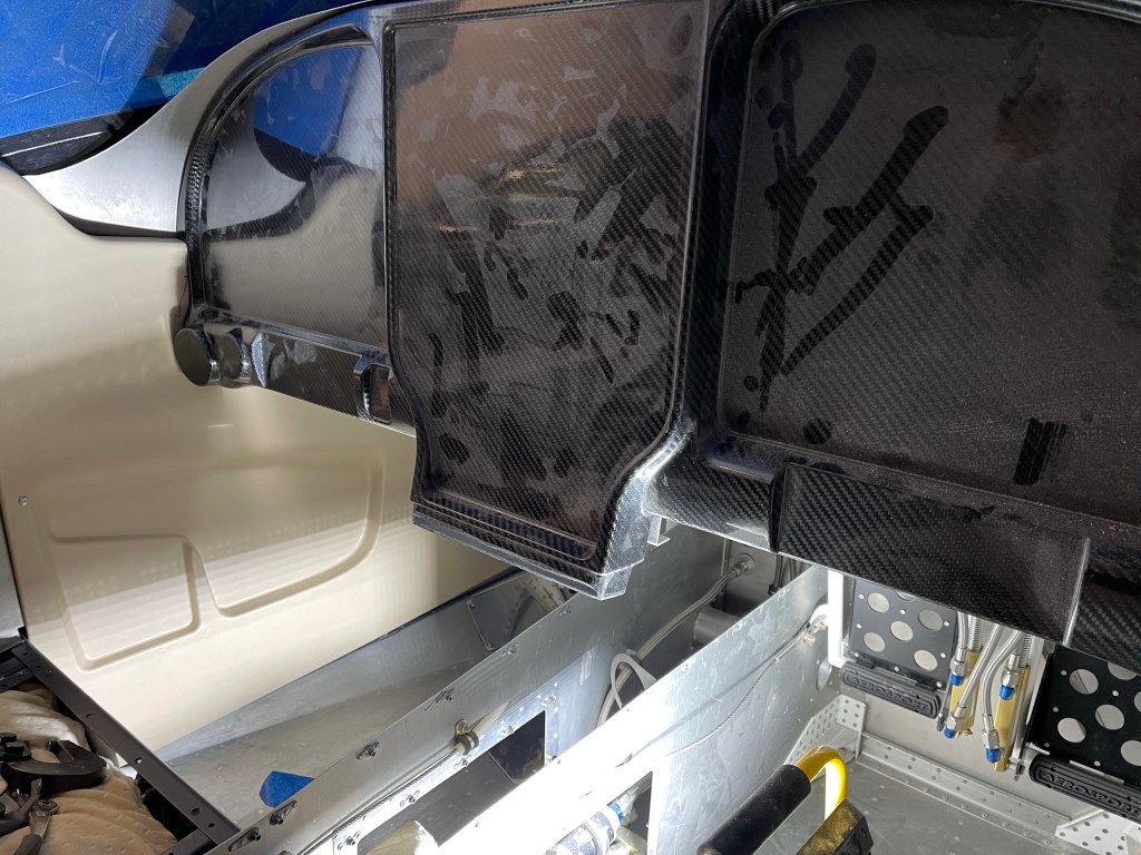
Then it was time to tackle the front panels. These require a bit more trimming, especially around the front door frame where I built things out a bit more with micro.
Front left panel in place
One trick I saw used was to use a compass scribe a line matching the contour of the area around the door frame. Trimming to that line, gives a good fit. This marking and trimming around the frame was done progressively until everything fit well. Taking a little off at a time is key here.
I then placed the instrument panel in place to make additional trims around the air vent area until it all fit well.
This process was repeated for the right side. I do have AC hoses routed down the right side, so I additionally had to trim the front of the panel to alleviate interference as the hoses leave the firewall and start their journey down the right side. I can now paint these when I have some time..
A very late post of this content that I found in my drafts.. Apparently I started on this, but never finished/published it.. so I’m doing it now.
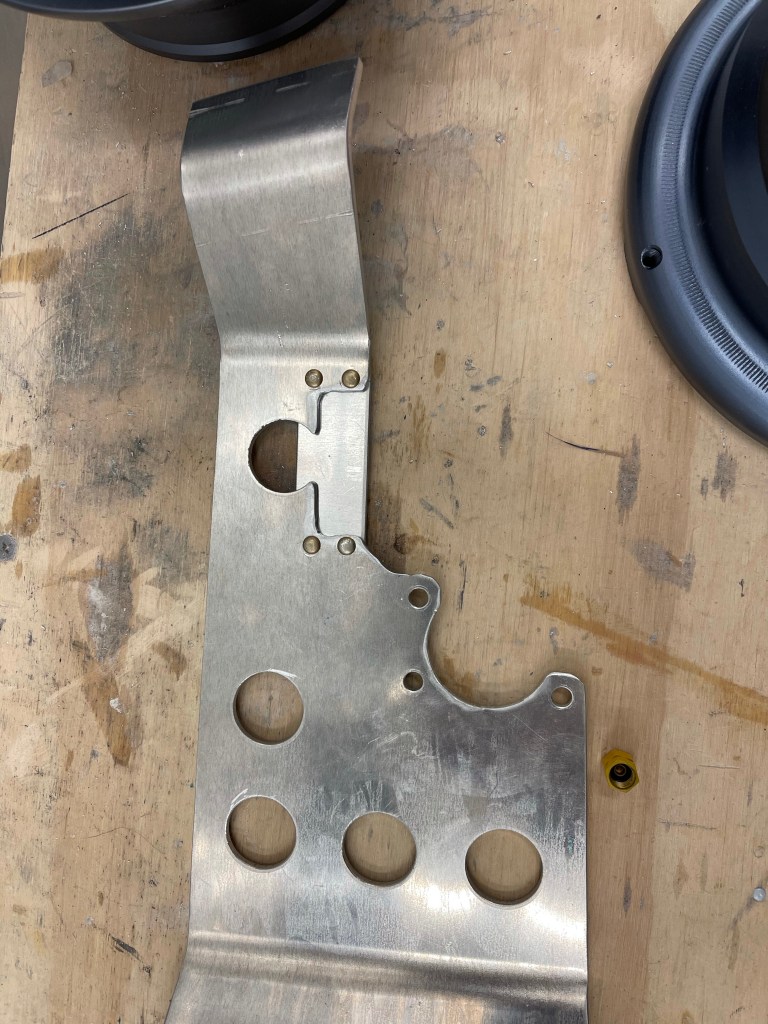
The wheel fairing brackets needed to be modified to accommodate the Matco brakes. The AN fitting for the brake line interferes so a section needed to be cut out as marked below.
I added an extra piece os .125″ material riveted on where the piece was cut out, but offset to allow a pocket for the brake line AN fitting to sit in.
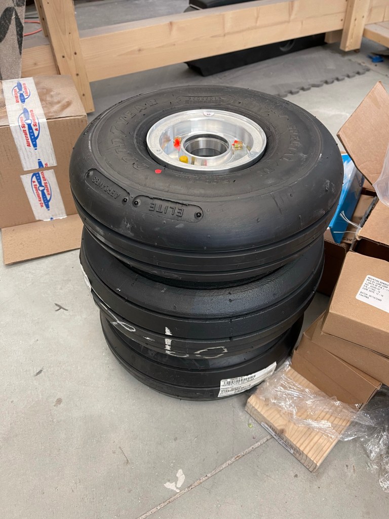
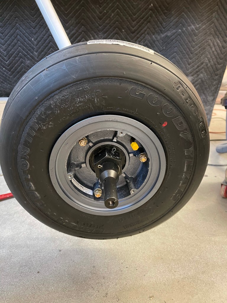
The wheels were prepped and the tubes and tires placed on them.
All 3 tires and wheels done.
Then the plane was lifted up onto the table with the help of several friends and family. It was much heavier than anticipated. I utilized a 2×4 through the wing spar area for a person on either side. One person lifting the tail and another lifting at the firewall. Yet one more person to help position the table.
Now that the plane was up on a table, I could then slide the gear legs up into the weldments. I used some grease (same as the wheel bearing grease I have) on the legs to help get them into place. Once close, I used a curved pair of tweezers to feel the edge of the hole in the leg itself. I made small adjustments to get the hole in the weldment aligned perfectly with the gear leg hole. Once I could “feel” the inside of the hole all around without any misalignments between the two, I then reamed out the hole to final size.
Bolt and washer(s) and nut were installed..
Left gear leg installed.
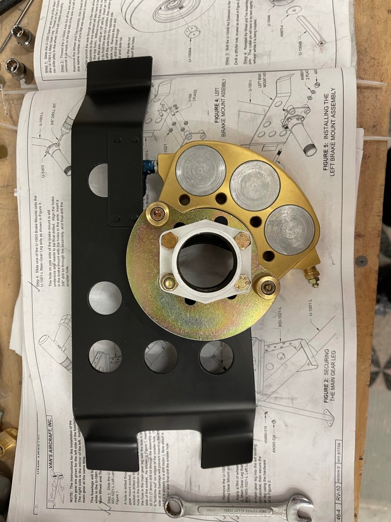
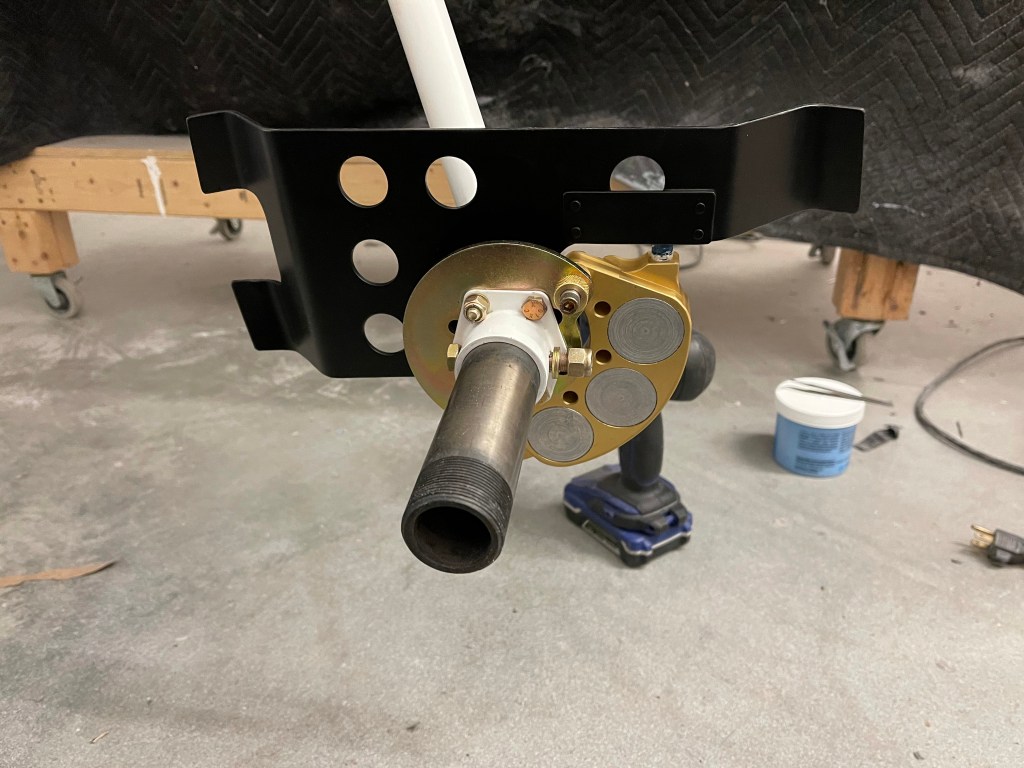
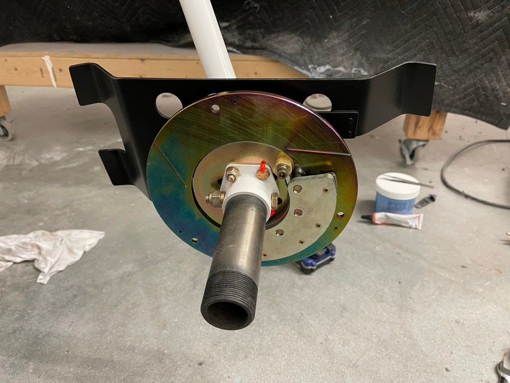
After priming the gear fairing bracket, I continued assembling the Brake assembly per the Matco and Van’s instructions.
The initial brake assembly was put into place and the axle was drilled for a bolt (which was later turned the other way to avoid interference)
Rotor and other pad in place.
The wheel bearings were then packed with grease using this nifty tool from Amazon.
Rather than oblonging the axle nut hole as depicted in the Macto instructions, I opted to drill a 2nd hole a little farther inboard as depicted below. The Van’s instructions were followed to count the number of turns required to remove the nut.. then the wheel/tire were removed and the nut added back the same number of turns. The axle was then matched drilled to the hole in the nut.
The assembly was then put back together and cotter pins added through the axle nut and the wheel fairing extension.
The same steps were repeated for the right side.
The nose wheel fork was prepped and primed.
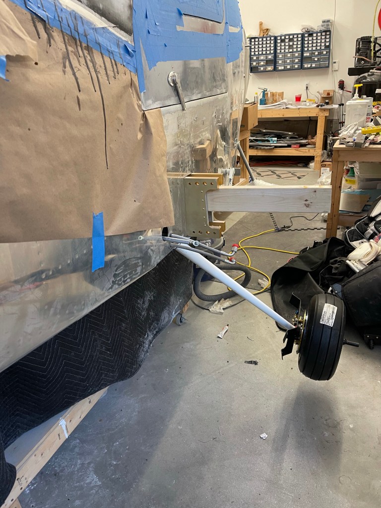
The nosegear leg was then put into place.
Initial fit of the nose wheel in place.
The rubber donuts for the nosegay were put into place, but not compressed down yet
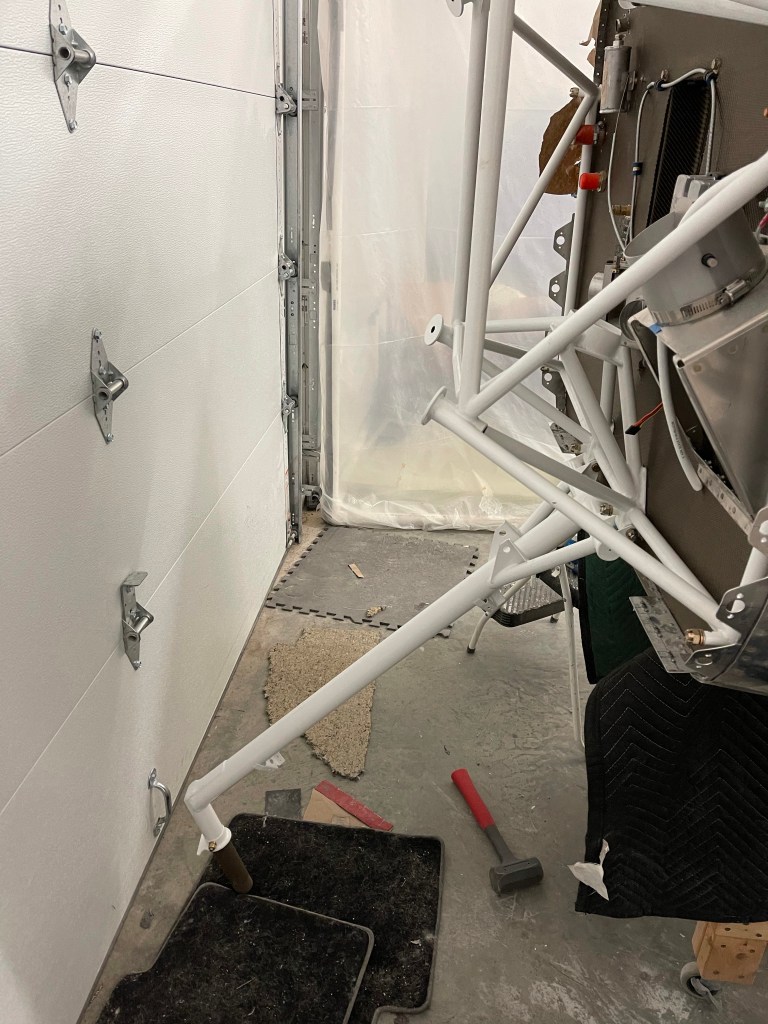
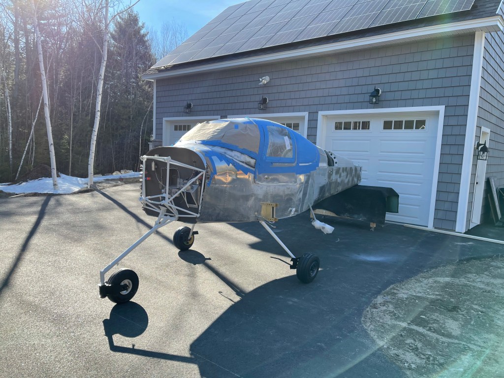
With all of that done, the plane was pushed off of the table and onto its own gear for the first time!!! Pictures below of it wheeled out into the driveway and back into the garage afterwards. For now, a table is used to hold up the tail until the engine is put on.
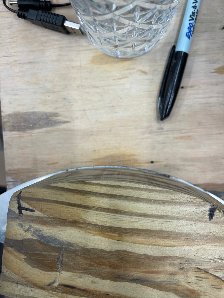
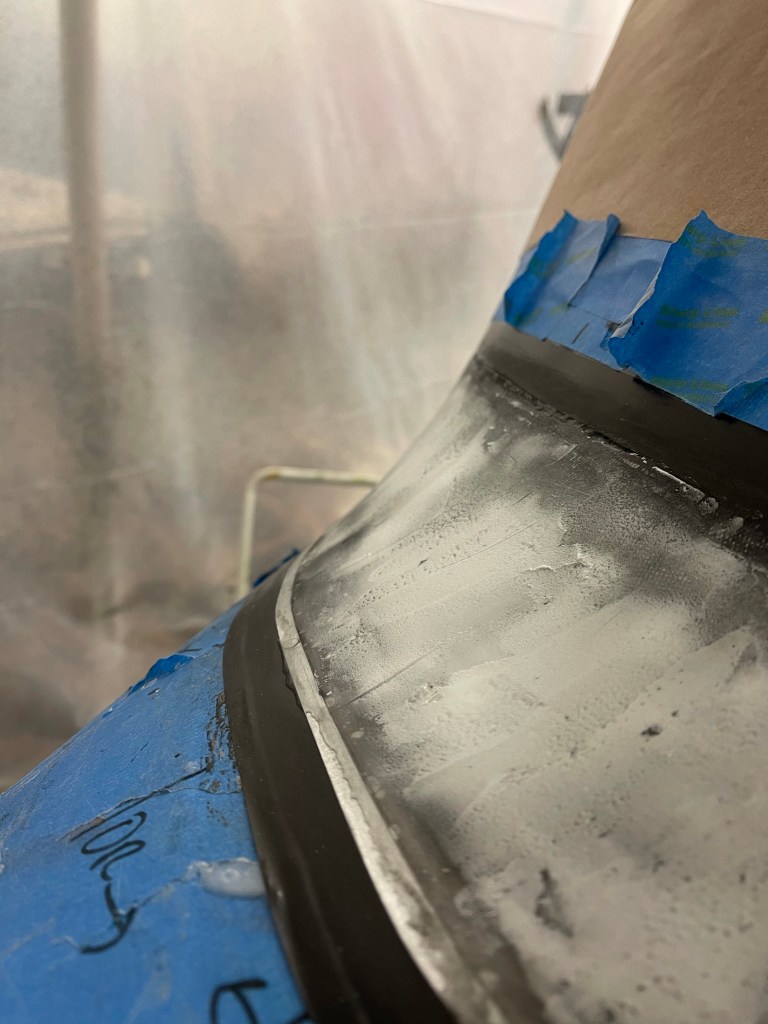
First up while the layup was curing was to make a 7″ radius sanding tool. I had a 4×4 piece of lumber that I ripped to be the same length as the width of the layup.. Then I marked the radius from the metal tool I had made onto the side. It took me a couple of tries to figure out how exactly to mark it (as you can see) in order to have it end up being correct. I then cut it out on my bandsaw and compared to me template.
Marking the 7″ radiusComparing the result to the template.
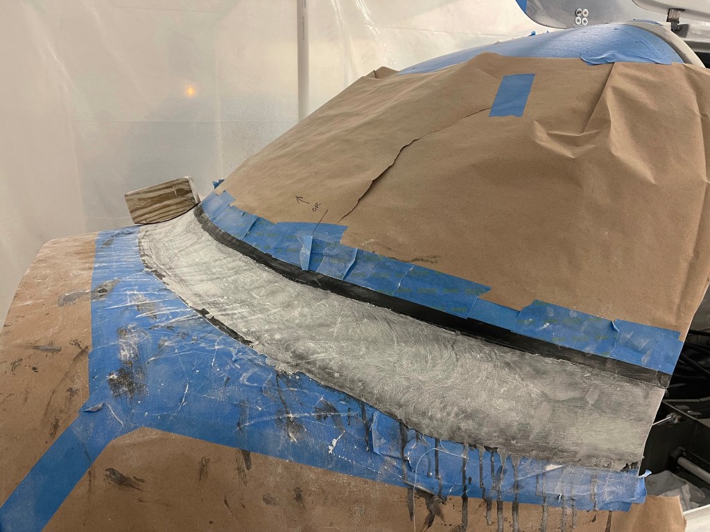
I used this tool with 50 grit sandpaper glued on initially to sand the shape across the front. The shape is mostly flat as you approach the sides where the leading edge of the door is. In between the front center and the extreme edges, the contour continually changes making it hard to sand. I ended up using the 7″ radius block I had made angled at about 45 degrees and occasionally used circular motions as well. I feel like it worked well.
The idea here is there are 2 layers of electrical tape on the windscreen and the metal fuselage. You continue to sand until you’re just scuffing the surface of the top layer of tape. Once that happens, you take the top-most layer of tape off and continue sanding with finer grit until you start scuffing the bottom layer. This will help create a feathered edge onto the mating surfaces. Once I was done with sanding (several days worth.. ) I started to fill some low spots with epoxy and micro.
Getting closer
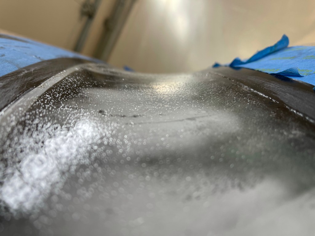
Once satisfied with the overall shape, you start to put a skim coat of epoxy down to seal up the final part and fill any pinholes. A very similar process to what I used to finish the overhead console. I used a squeegee and a foam roller to get good coverage and left it to cure overnight.
Closeup of the final shapelittle bumps of epoxy will be sanded out once cured.
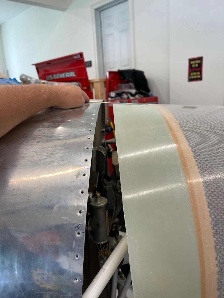
Once done, I pulled off the tape to see the result.. Here is a shot along the left side.
A view from the inside where you can see the really nice black line all the way around the base of the windscreen. Very happy with how this turned out!
I still have some touchup to do along the feathered edges and then I will be using some high-build primer to paint the fairing. I’ll leave it that way until paint.