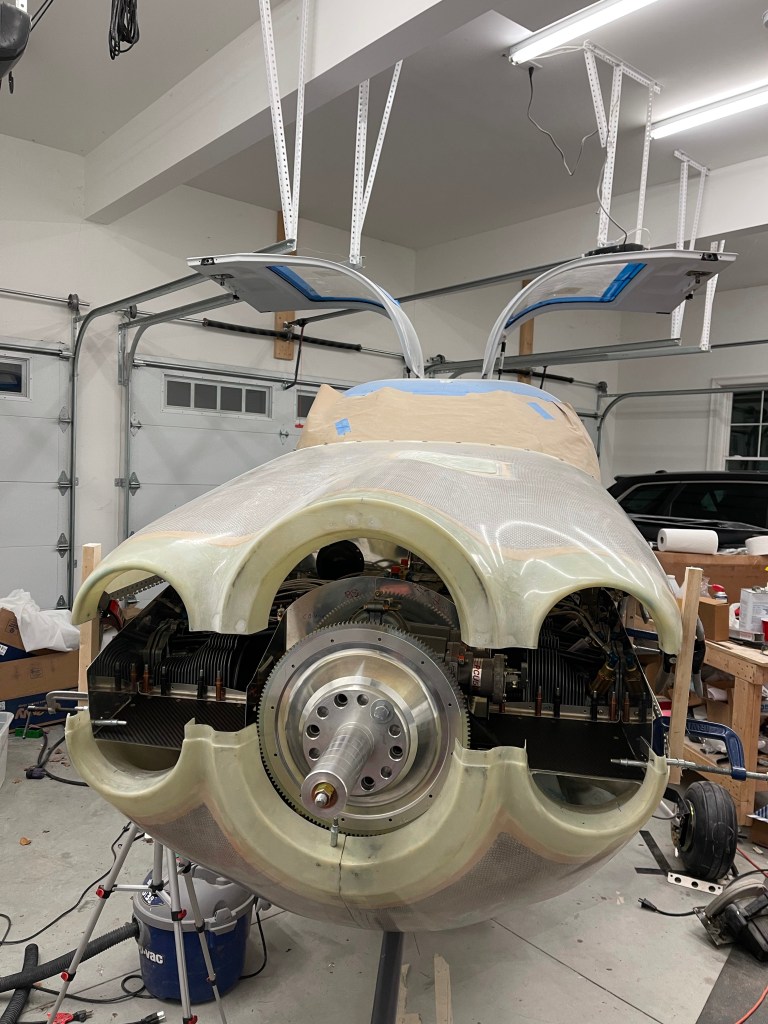
In order to get the top cowling back on, the baffle needed to be trimmed. I saw two ways to do this, and I ended up sort of using both. I started by elevating the top cowl 6″ above the lower cowl. Care was taken to make sure it was aligned both fore, aft, left, and right to the bottom cowl. I just used some pieces of scrap wood and clamps that I had lying around on each corner on the outside of the cowl. I measured in multiple locations along the horizontal split to be sure I was satisfied before moving on.

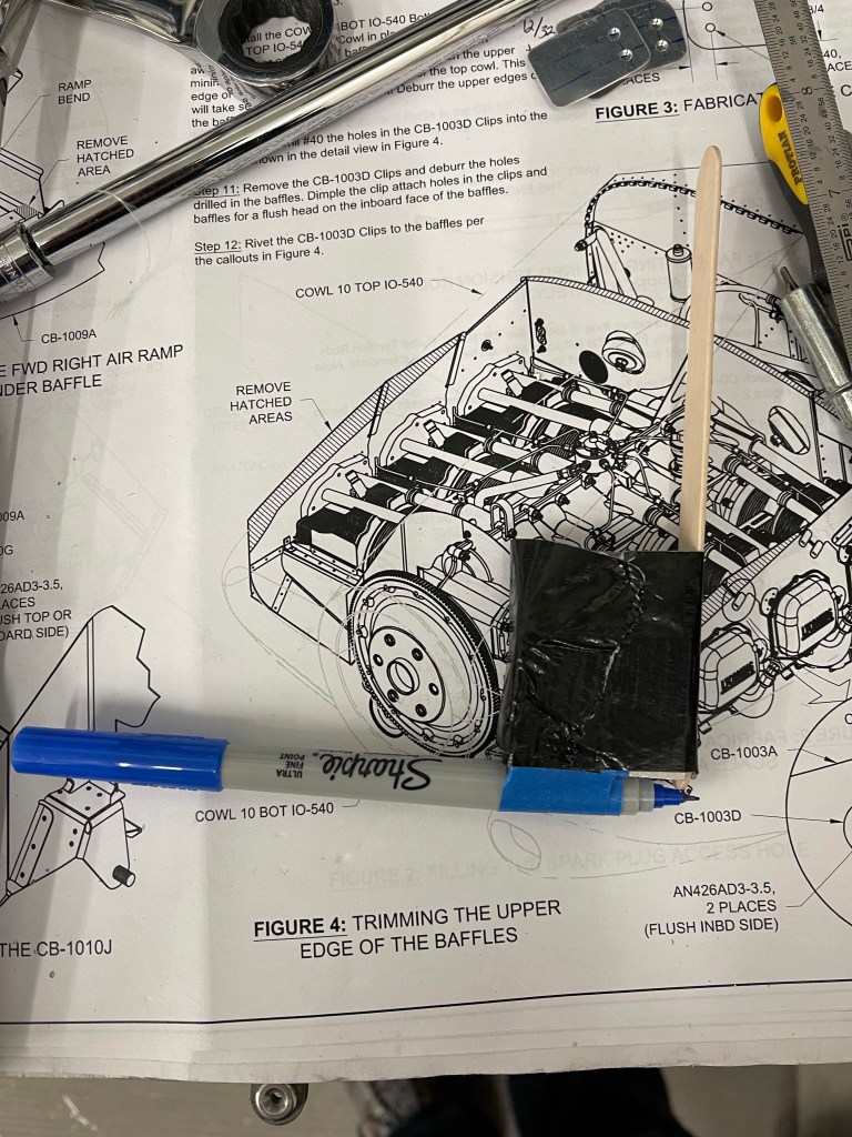
I then made a tool out of a tongue depressor and an aluminum block I had. I taped a sharpie to the bottom of the block and adjusted the stick to get exactly 6″ from pen to top of the stick. I didn’t take any pictures, but the idea here is that you have enough room (with the 6″ elevation) to get your hands/arms inside to hold the stick at a 90 degree angle with the sharpie along the inside of the baffle. Holding the stick on the inside of the upper cowl, you move it aft tracing the contour of the top cowl onto the baffle which will serve as a trim line.
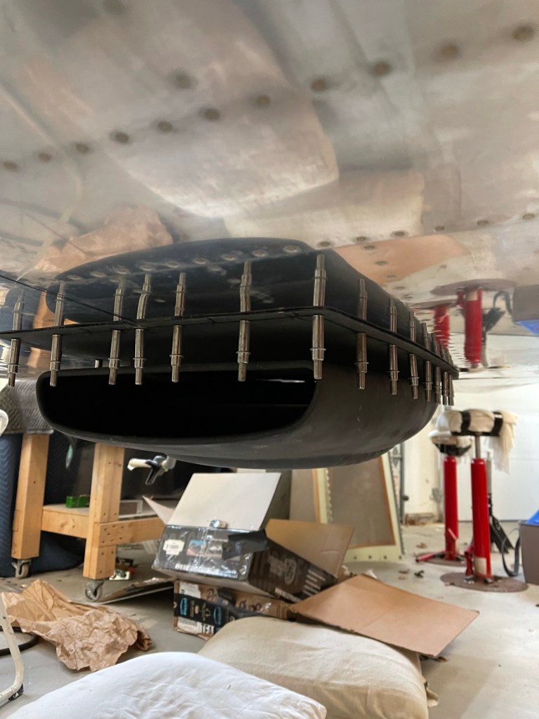
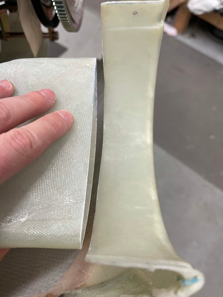
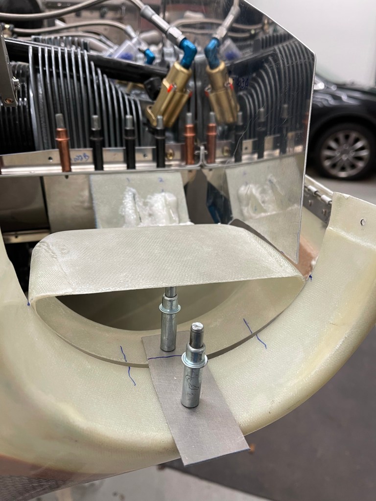
I then trimmed to that line. That basically got me to flush. One could certainly add some extra to the length of the stick to get the the gap you’d like to achieve. Instead, once the initial trim was done, I utilized the 2nd method of paper clips all along the baffles. You barely stick them on and then place the top cowl into position. They slide downward and give you an exact indication of how much gap you have at that location to the top cowl.

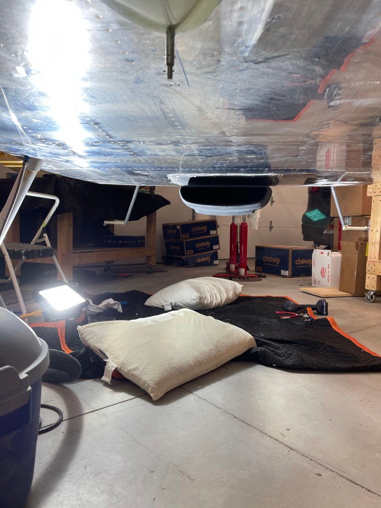
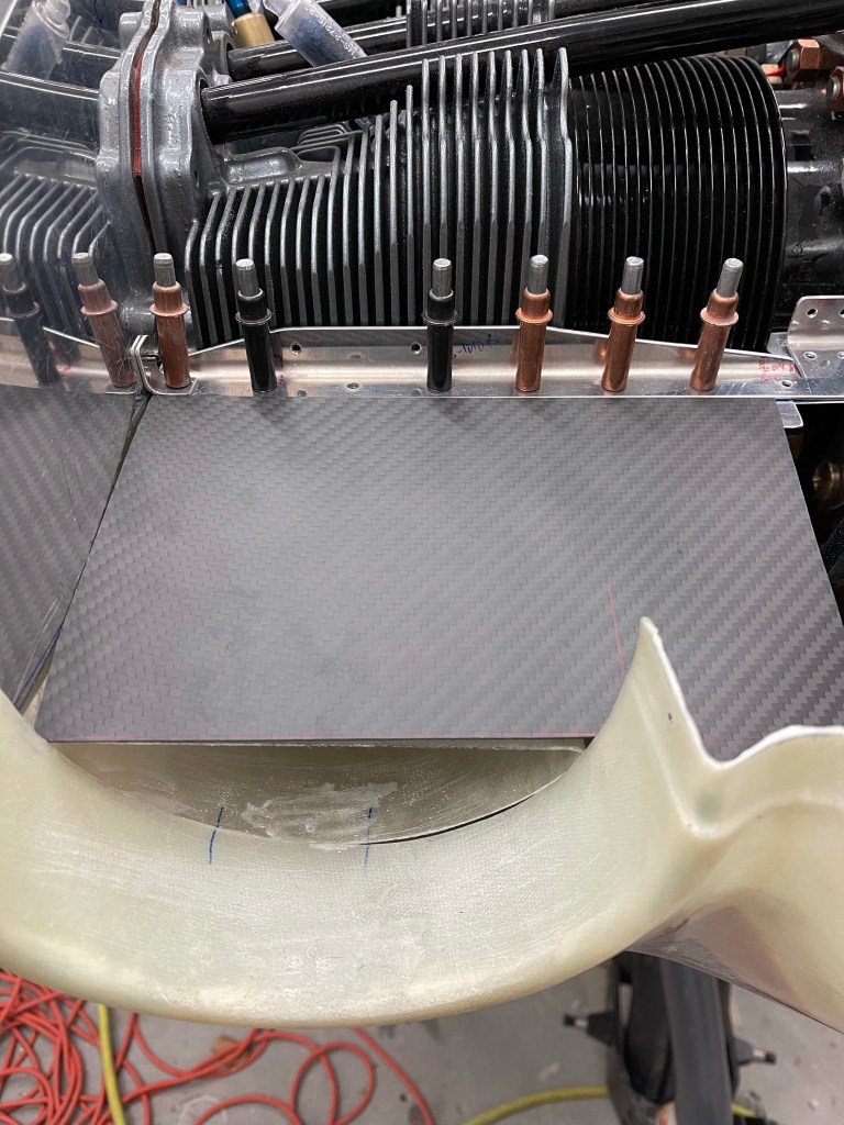
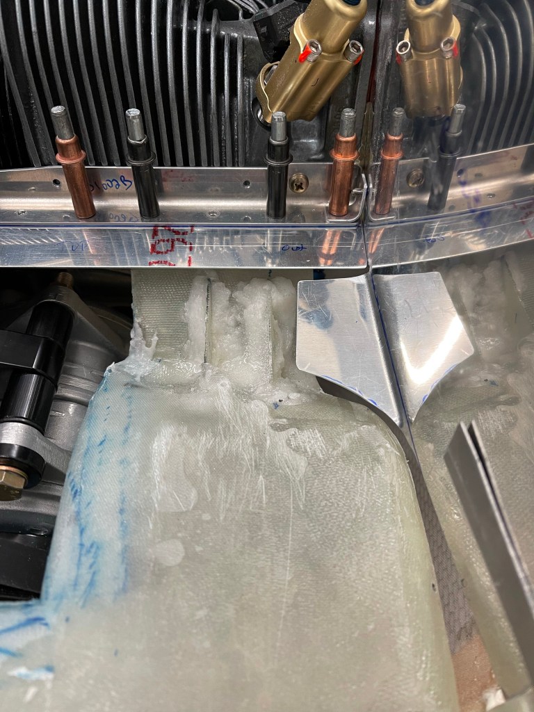
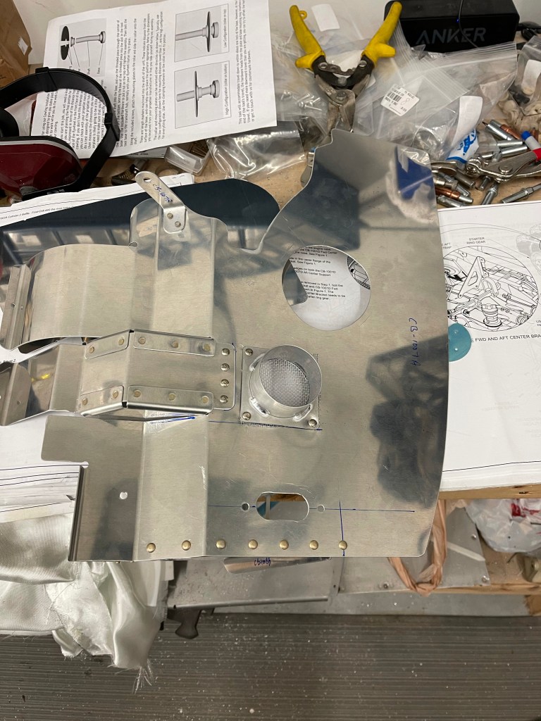
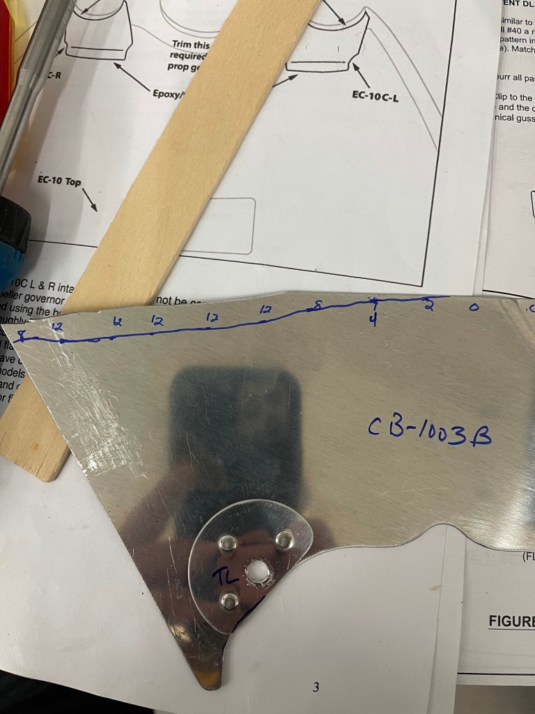
Below you can see the results of the first attempt. You’re shooting for somewhere between 12/32″ and 16/32″ gap per the plans. At each paperclip location, I wrote the number of 32’nds needed to get to 12/32″ by measuring how high each paperclip was above the edge of the baffle.

Those measurements basically were used to draw a new trim line.
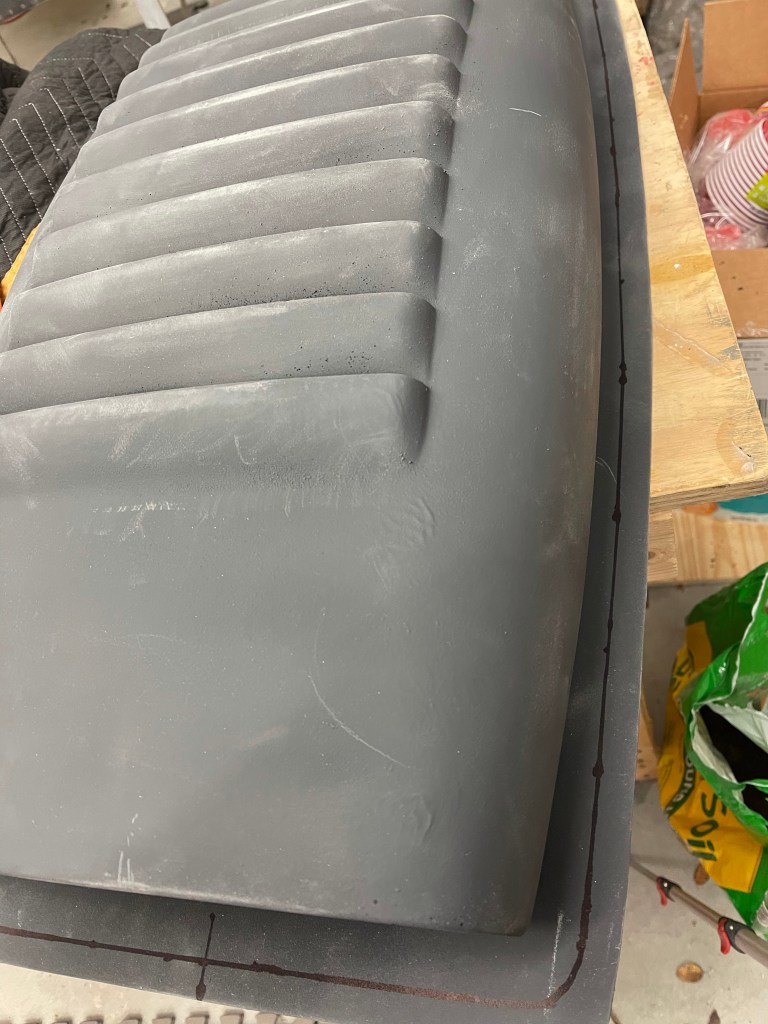
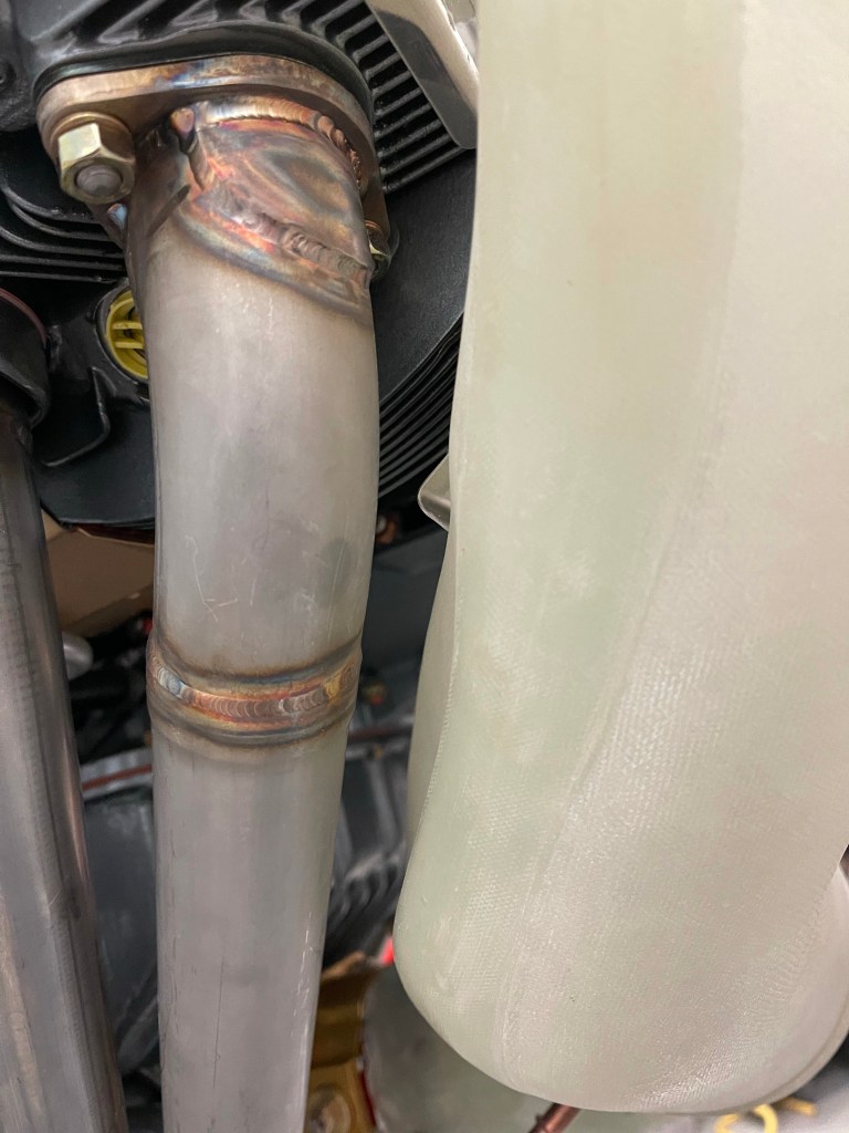
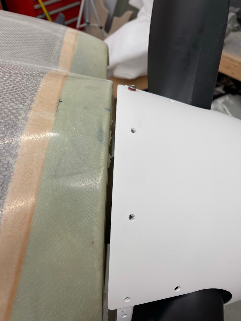
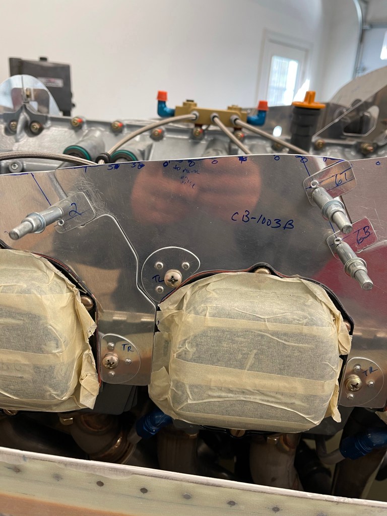
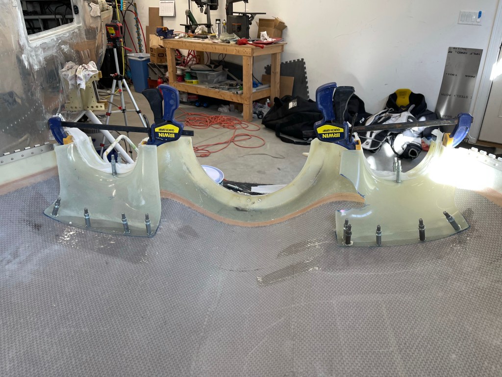
I ended up doing this for a couple of cycles until I was completely satisfied with the gap all the way around. Making smaller adjustments in specific areas as I went. Below isn’t the best picture, but it was the results of the baffle trimming with a gap to the top cowl.

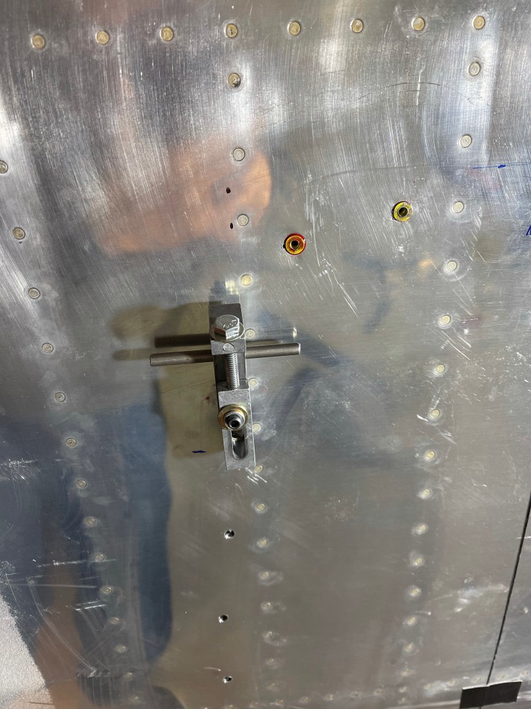
I fabricated the clips and drilled them into position per the plans. I’m holding off riveting most of this stuff until later.
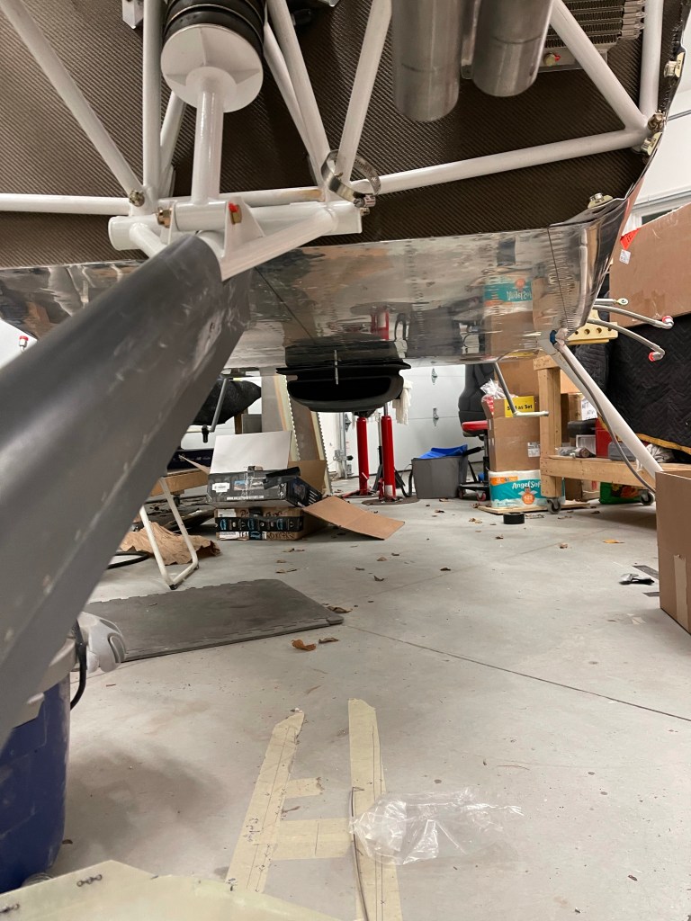
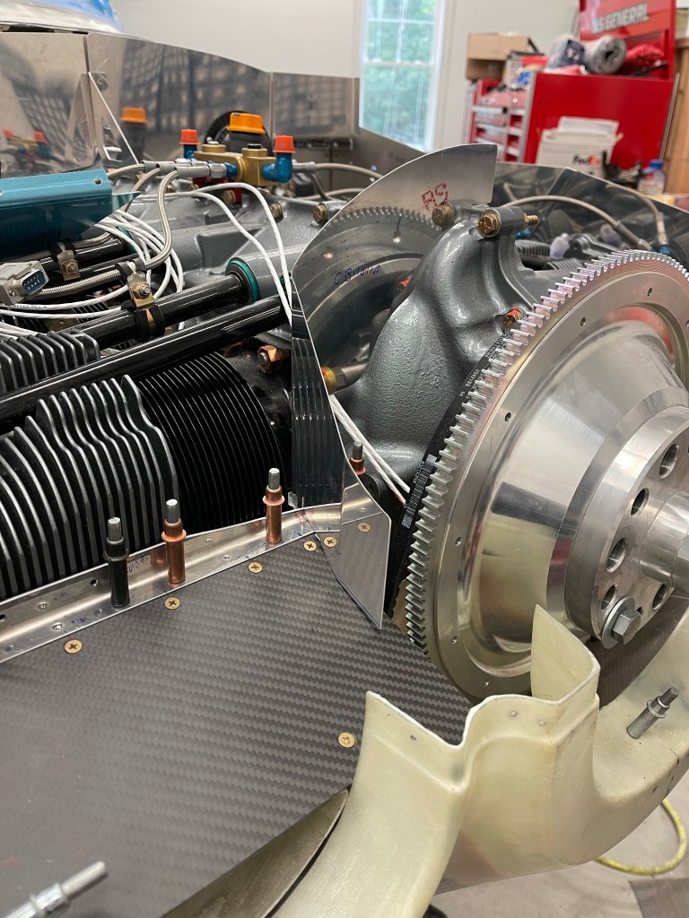
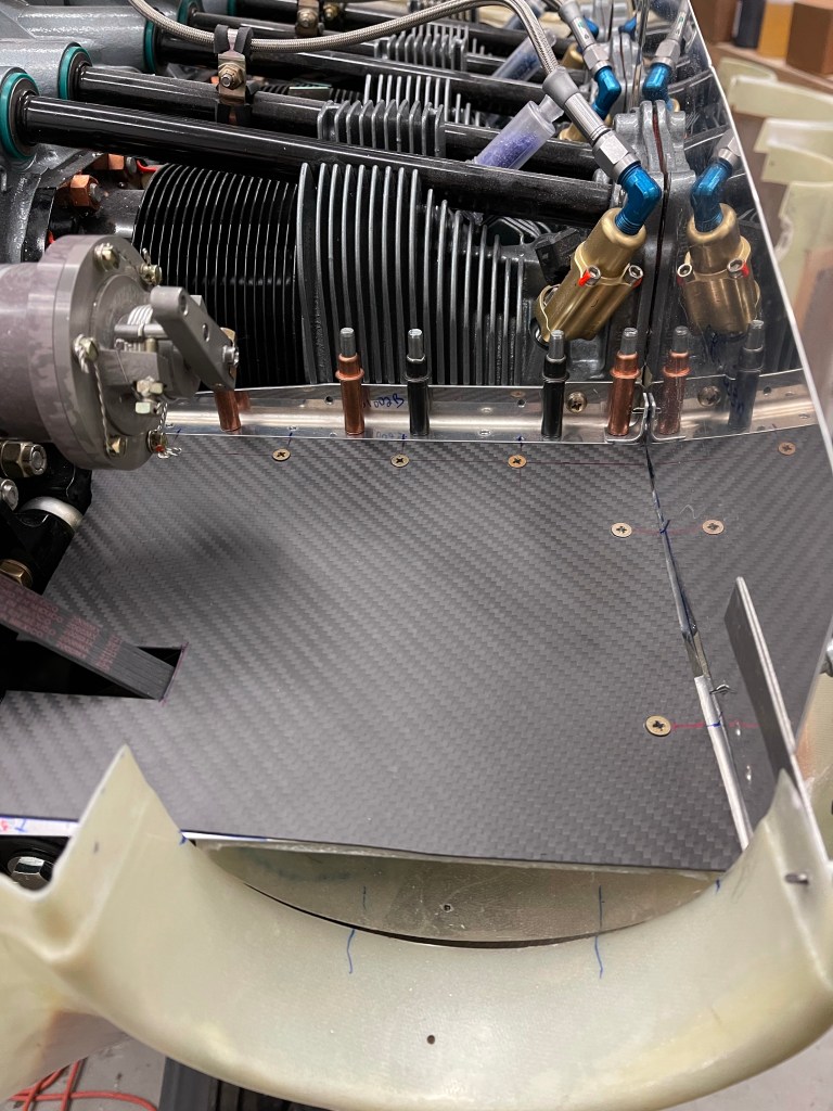
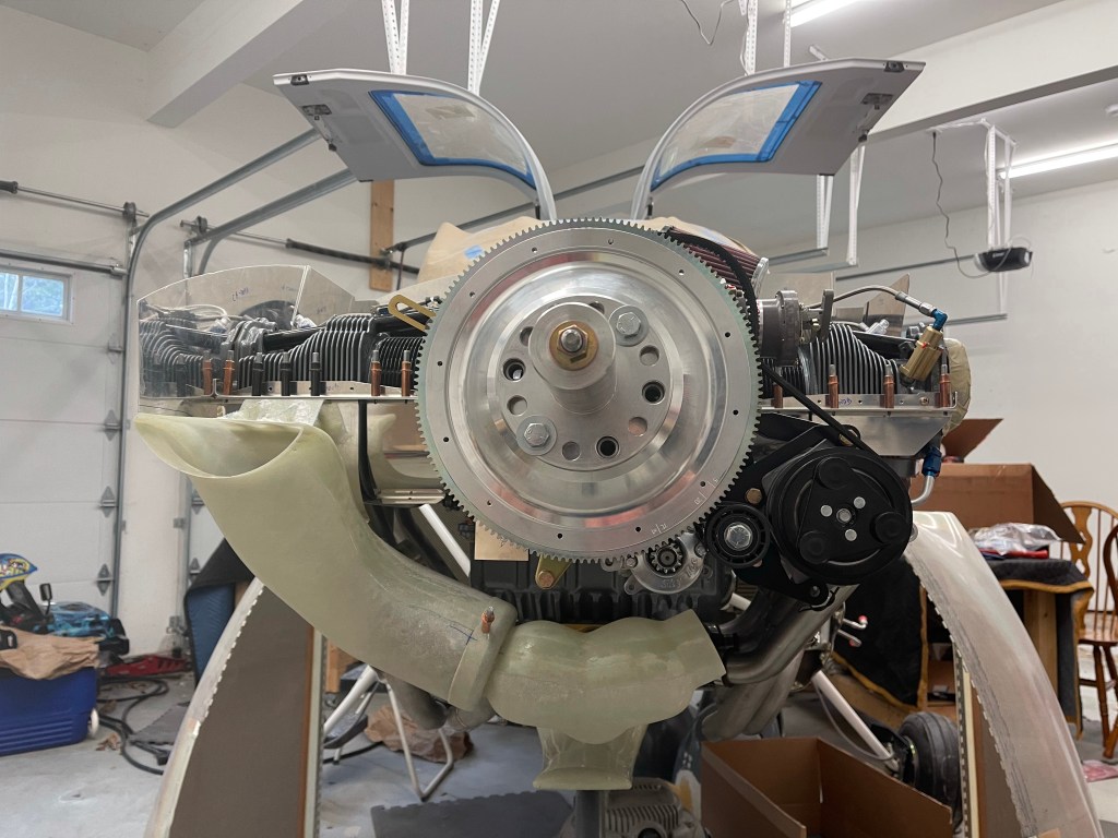
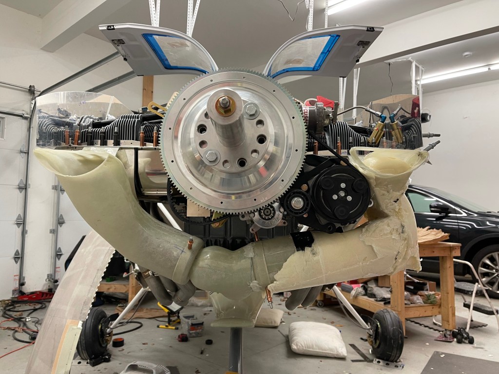
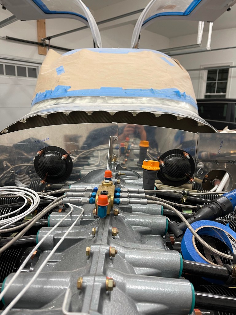
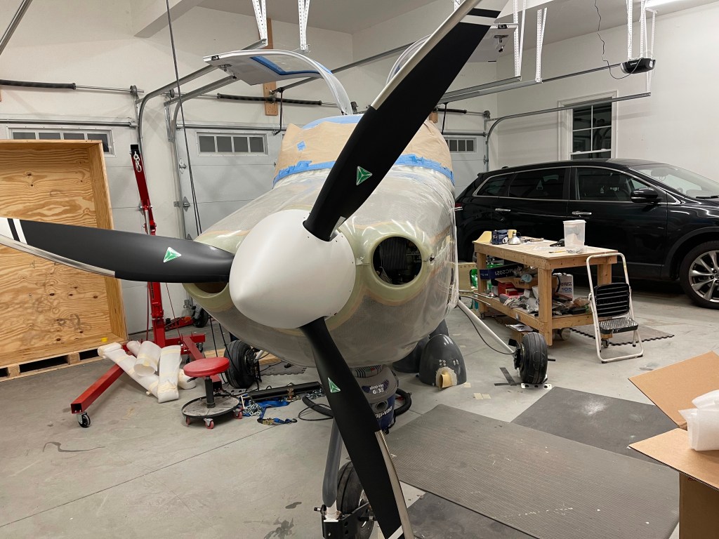
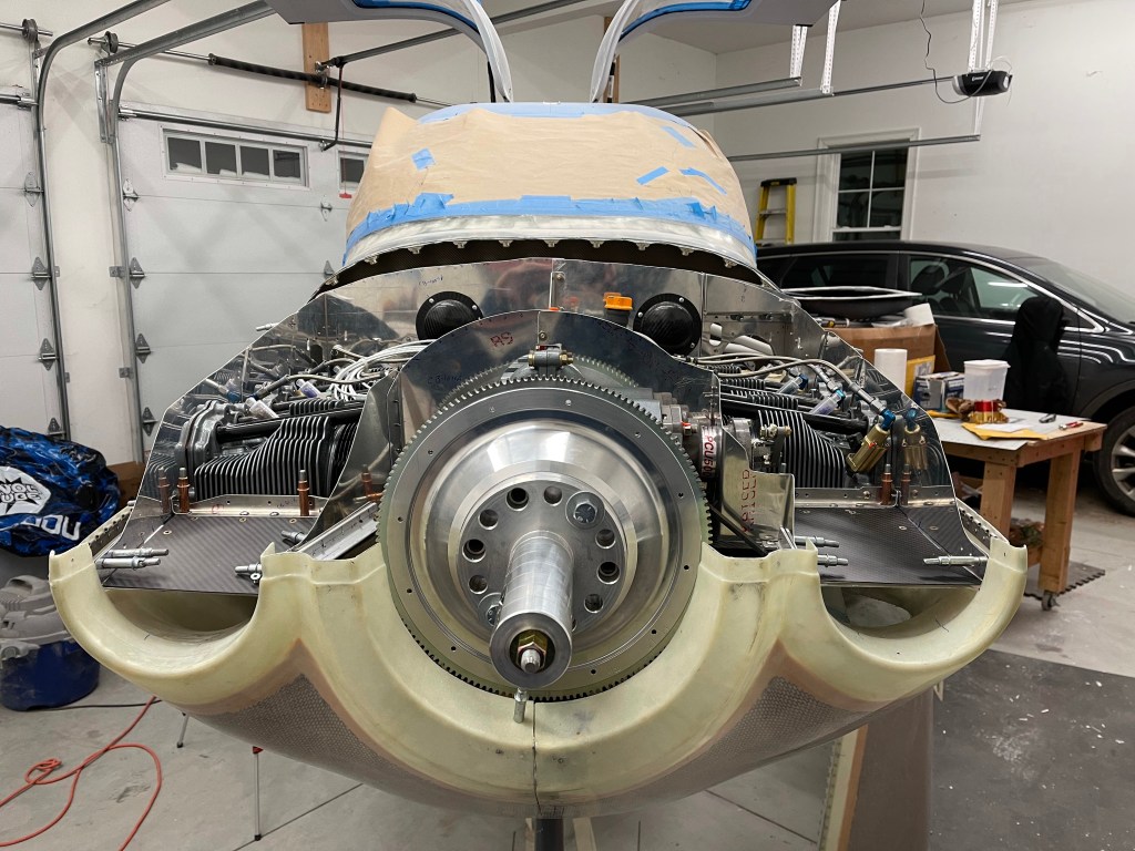
Now that the baffles were trimmed, I decided it was time to affix the top cowl inlet ramps. I placed them into position with clecos and some scrap metal strip to hold them in place at the front.

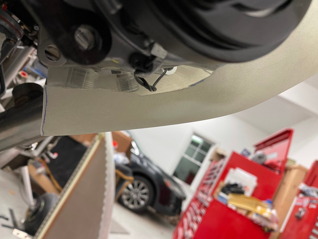
I then test fit the cowl and had to trim the outer side baffles more to account for the curvature. I did get somewhat lucky due to my cowl being so far forward based on my prop/spinner setup compared to most. The ramps didn’t require trimming at the prop governor to at least test fit. I did end up trimming around to give some more clearance, which I’ll foam in later to provide a good backing for baffle material.

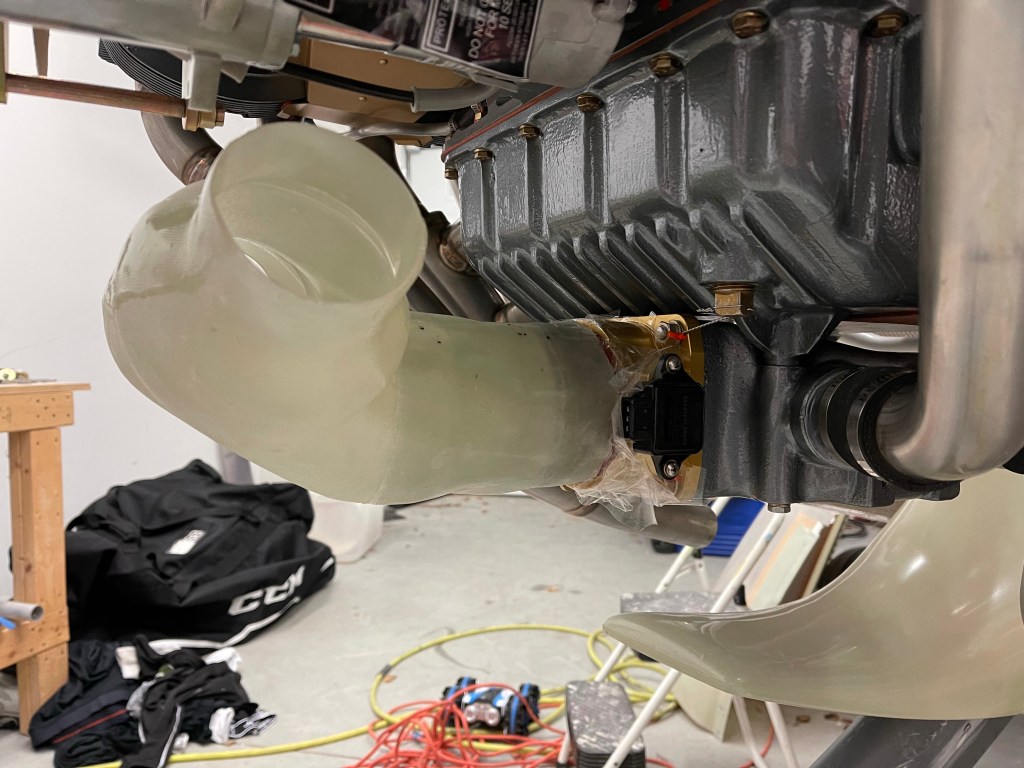
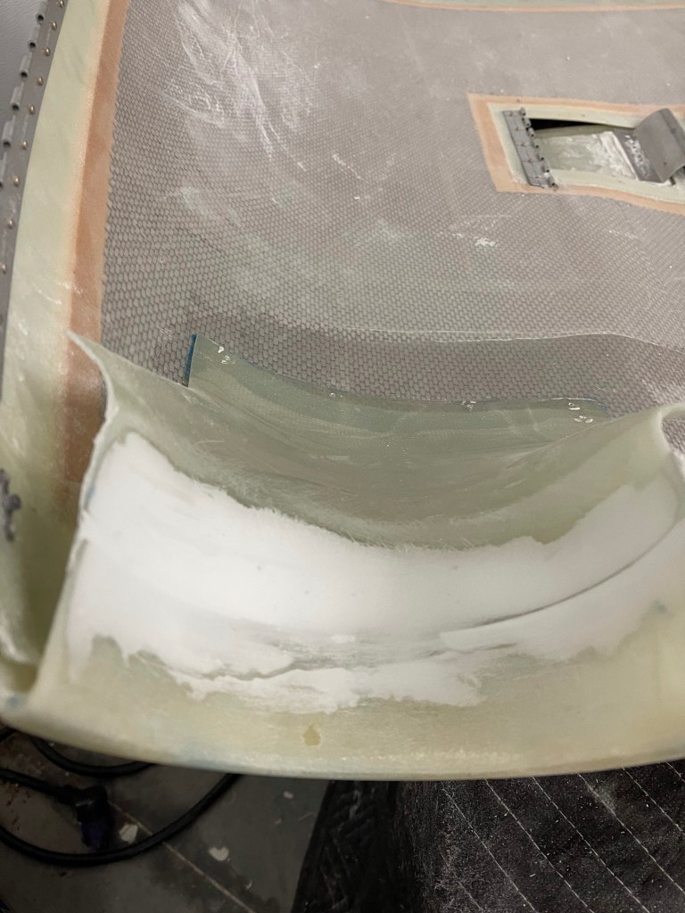
Once I was happy with their location, I epoxied them into place. Later I will layup some cloth, but for now just epoxy to hold them in position. I also did a single layer of cloth and some peel ply on the inlet circle just to hold that area into position.

I then laid up 3-4 layers of cloth for the underside of the circular inlet.. Placed that into position and let it cure. I sanded down the outside area and added micro. Once that was cured, I sanded to a smooth finish.

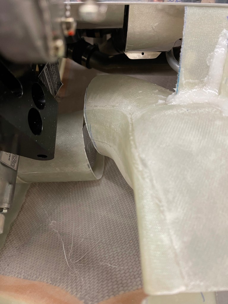
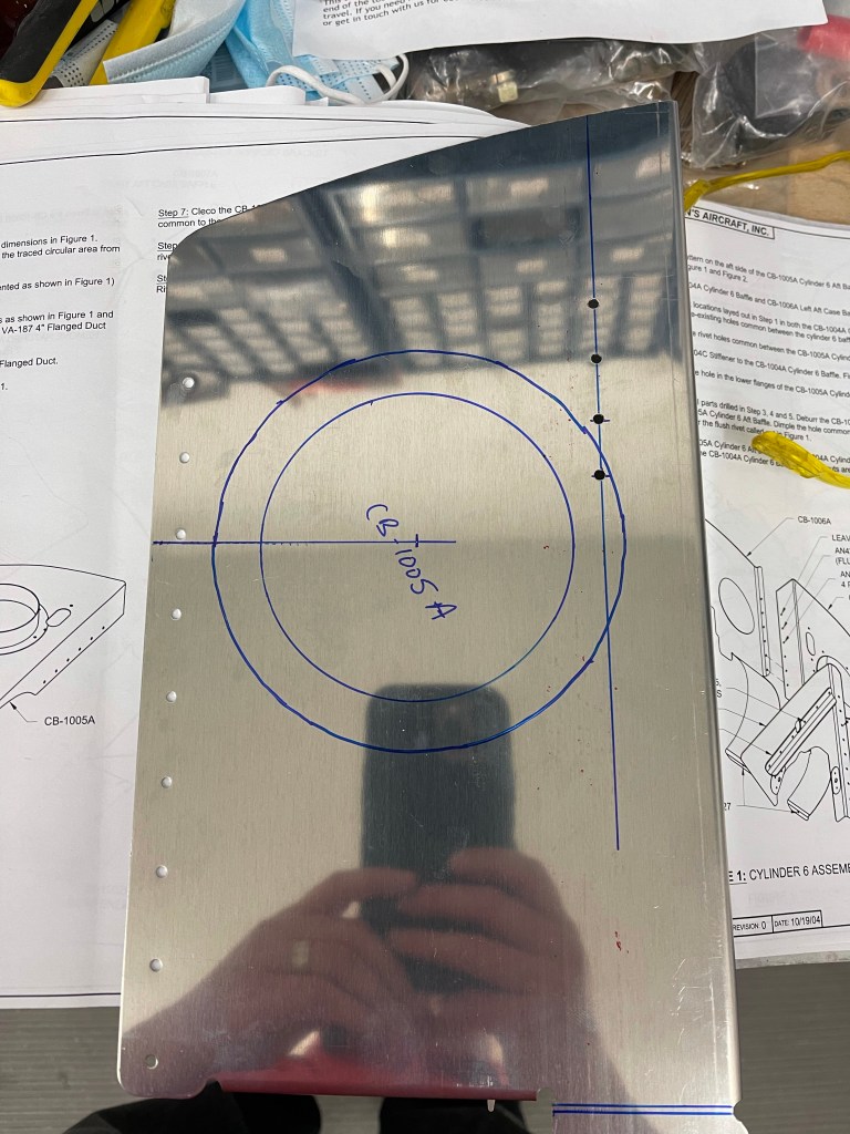
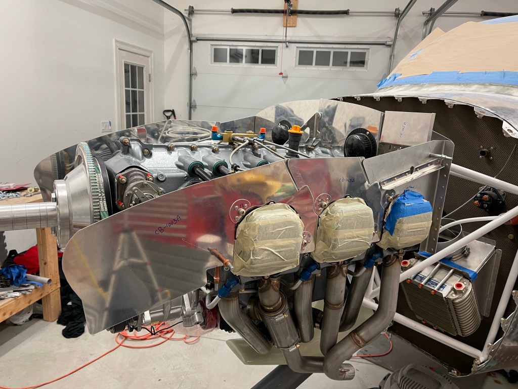
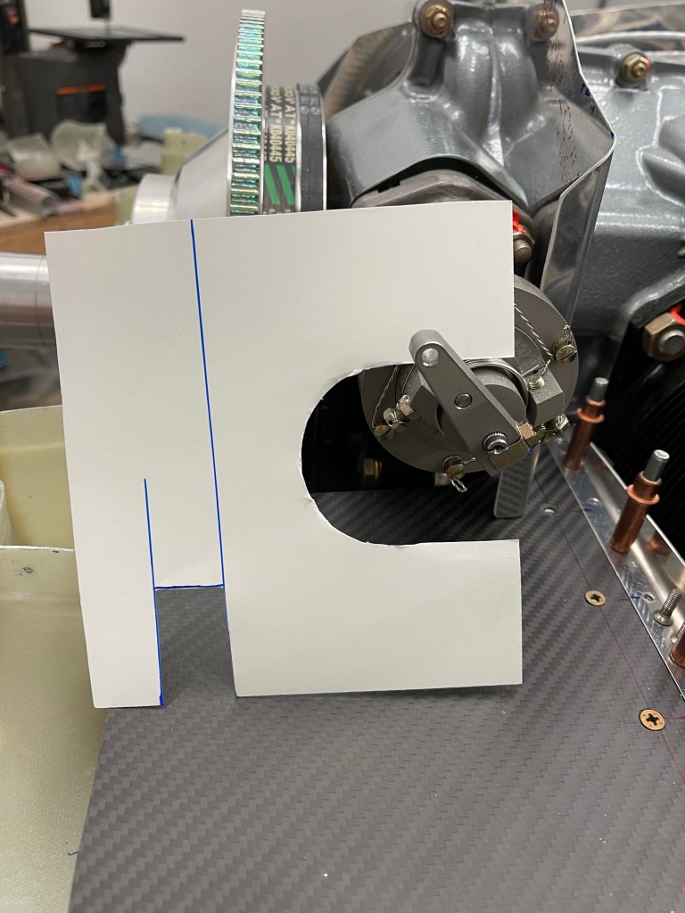
With the upper ramps completed enough for now, I moved on to customizing the center baffles. I started with the right side, seeing it’s the easier side without compressor interference to deal with. I cut the stock baffle leaving just enough flange to rivet a new piece that would angle toward the inboard side of the inlet. I first made a template from construction paper and got it as close as I could. I transferred to metal and worked on trimming to get a good gap to the upper inlet ramps.

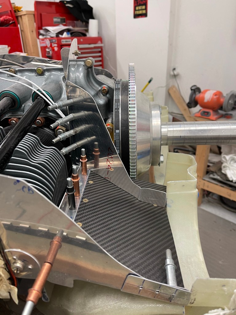
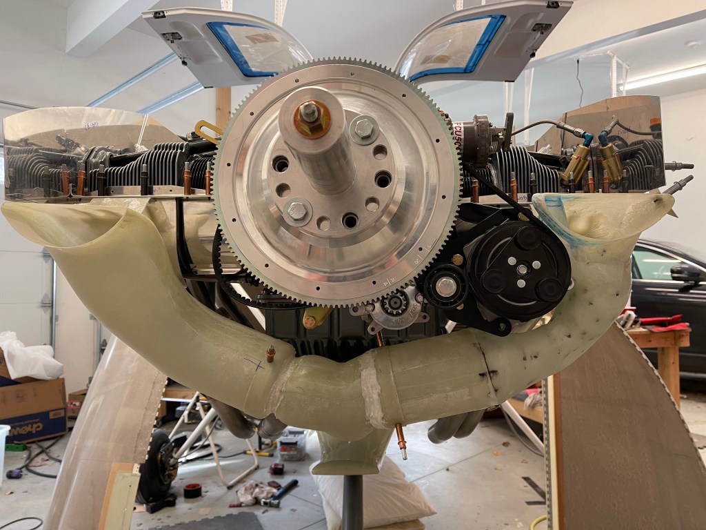
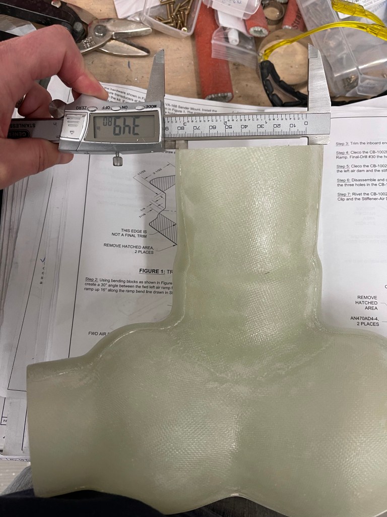
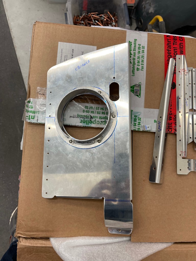
I then spent some iterations trimming this custom piece to match the curvature of the upper inlet ramp with some gap for baffle material. Below are the results.
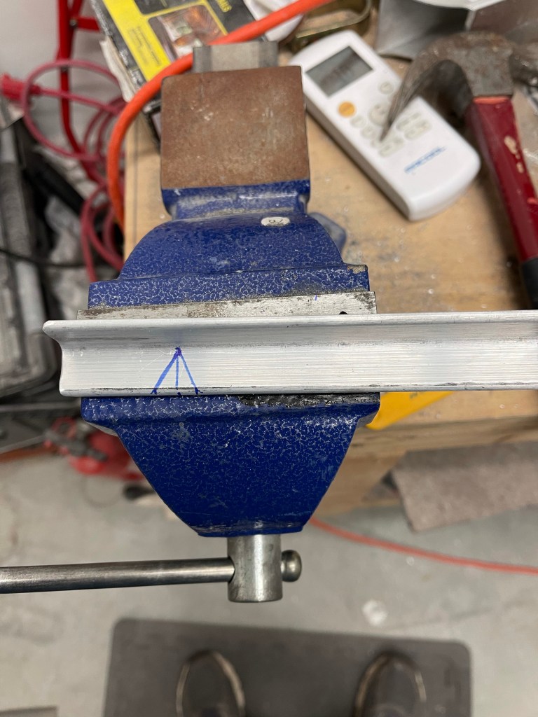
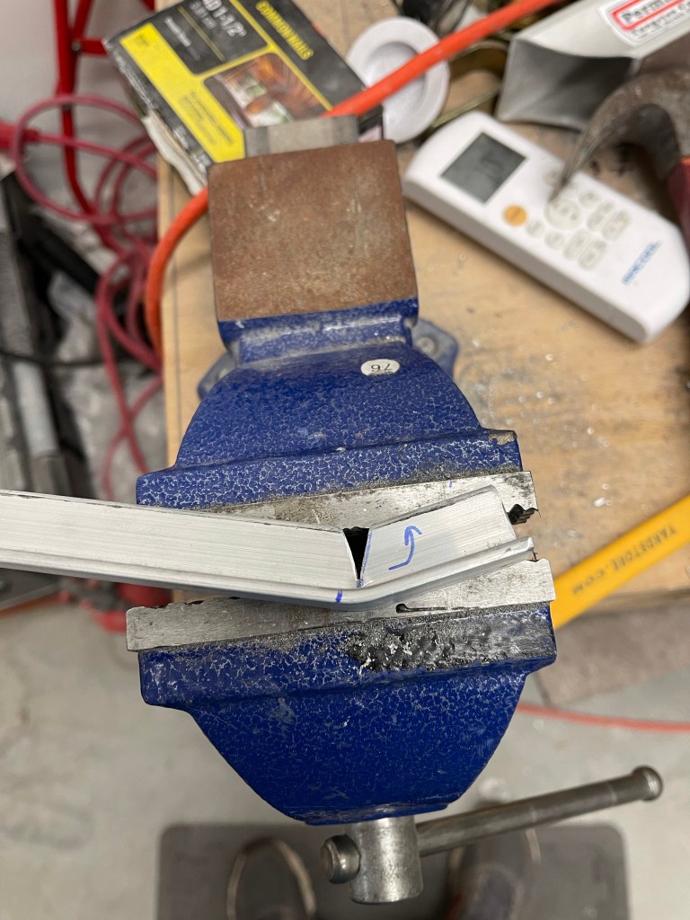
To hold the inboard side in place I fabricated up some 3/4″ x 0.125″ Angle. Seeing there was a slight bend in the baffle I just created near the inlet, I marked a cut to match that bend in the angle. I marked and cut out a “V”

Below is the end result after match drilling and cleco’ing the baffle to the angle.

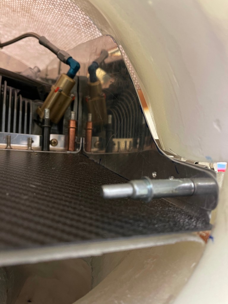
I utilized 3 screws to tie the aft piece of metal holding the carbon fiber ramp to the front pieces, including the piece of metal that runs under the carbon fiber ramp. I trimmed the excess away on the inboard side of any carbon fiber and metal plate so it didn’t protrude past the angle.

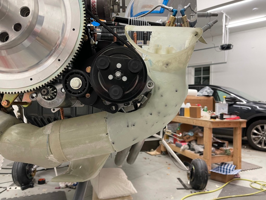
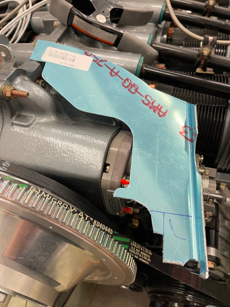
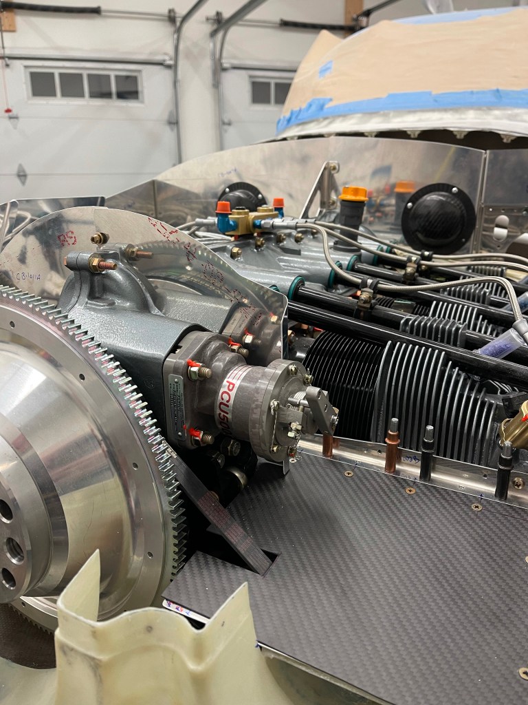
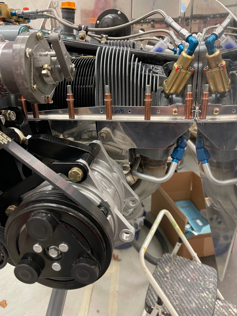
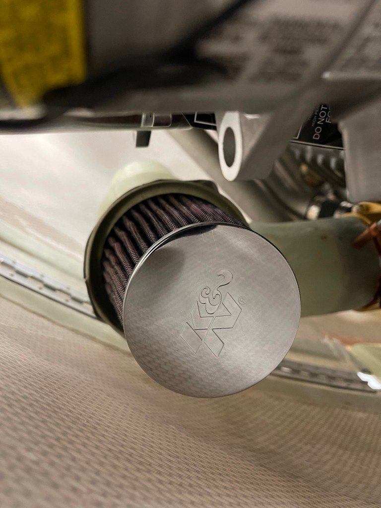
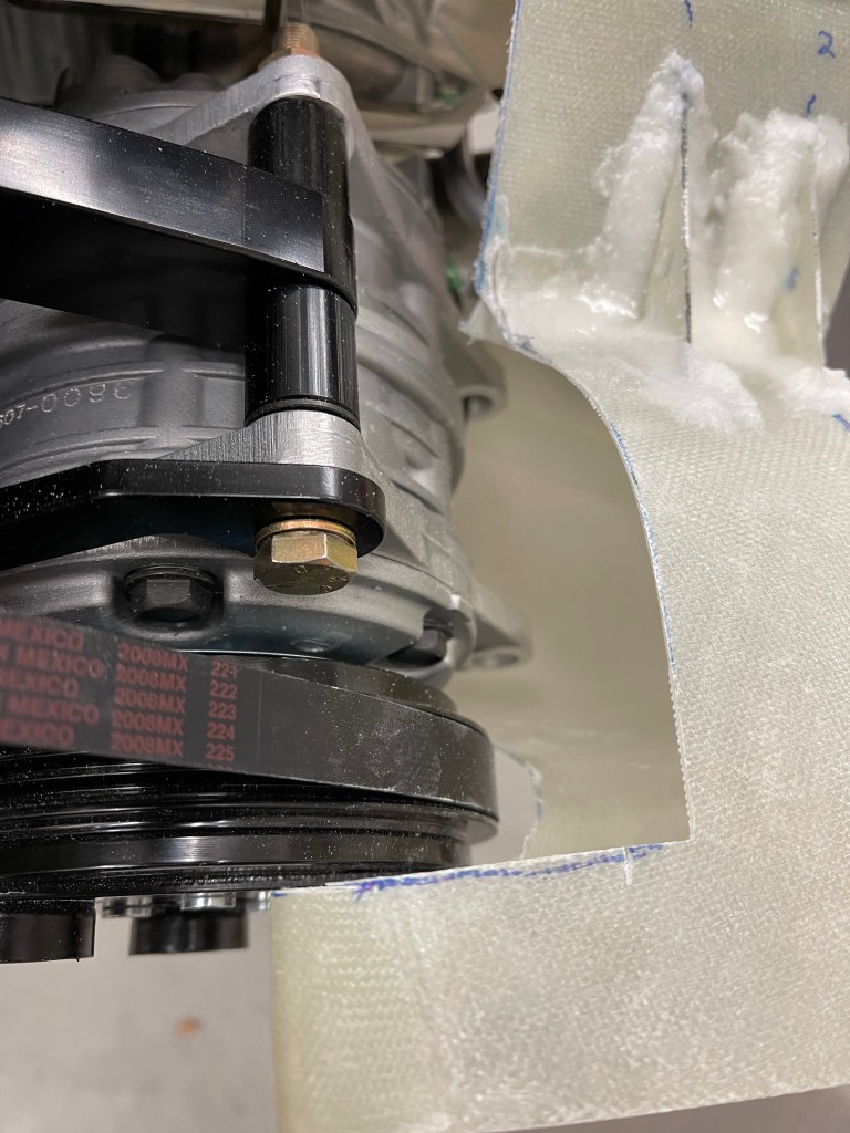
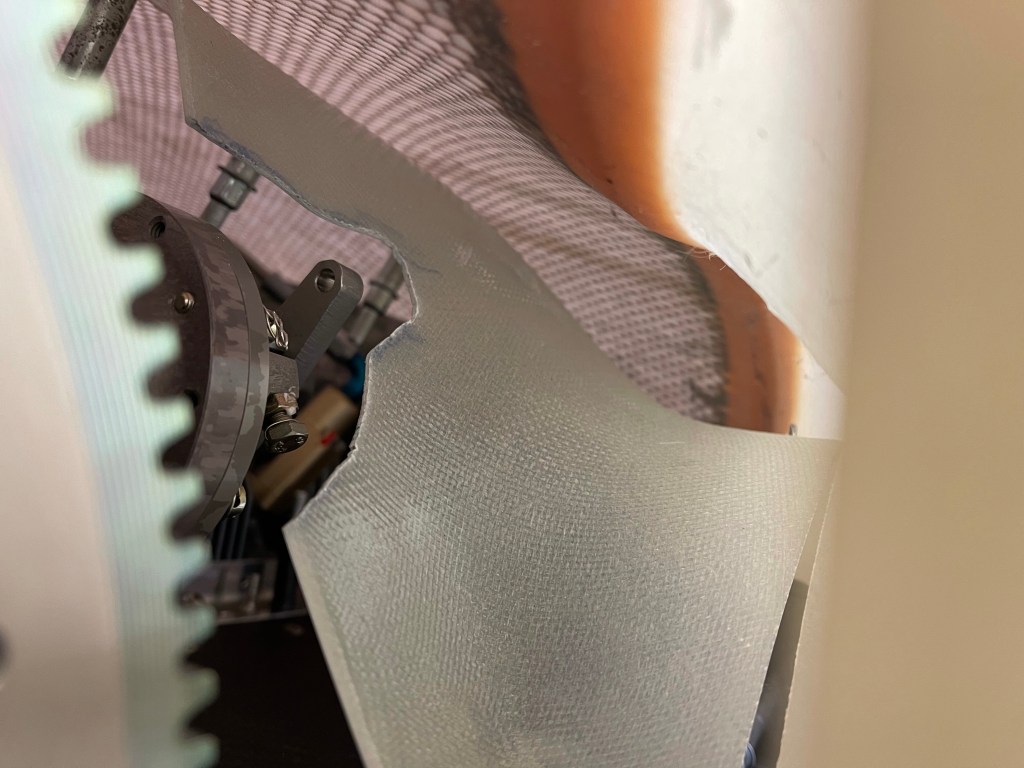
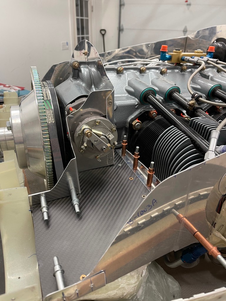
I then did a similar thing using a template on the left side. I decided to use one piece of metal to wrap around the governor and bend around the AC compressor belt to box it out of the inlet area.

Once I was satisfied with the paper template, I transferred it onto metal, cut it out, and made the needed bends as shown below.


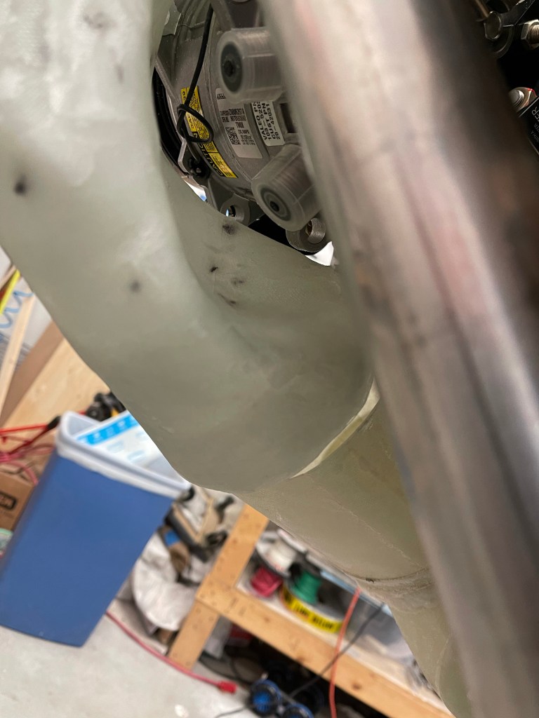
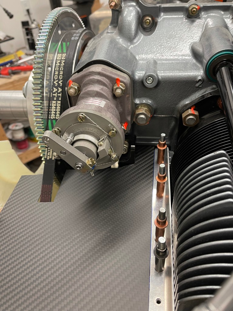
I then worked to fabricate another short piece of angle with a notch cut out for AC belt clearance to hold the inboard side in place. I drilled 2 holes for #6 screws to attach to the stock baffle that I had cut off and left a bit of a flange for connecting my custom piece to.


This was a lot of work!