Empennage Attach Complete

For now.. The only thing remaining is to adjust the elevator trim servo.

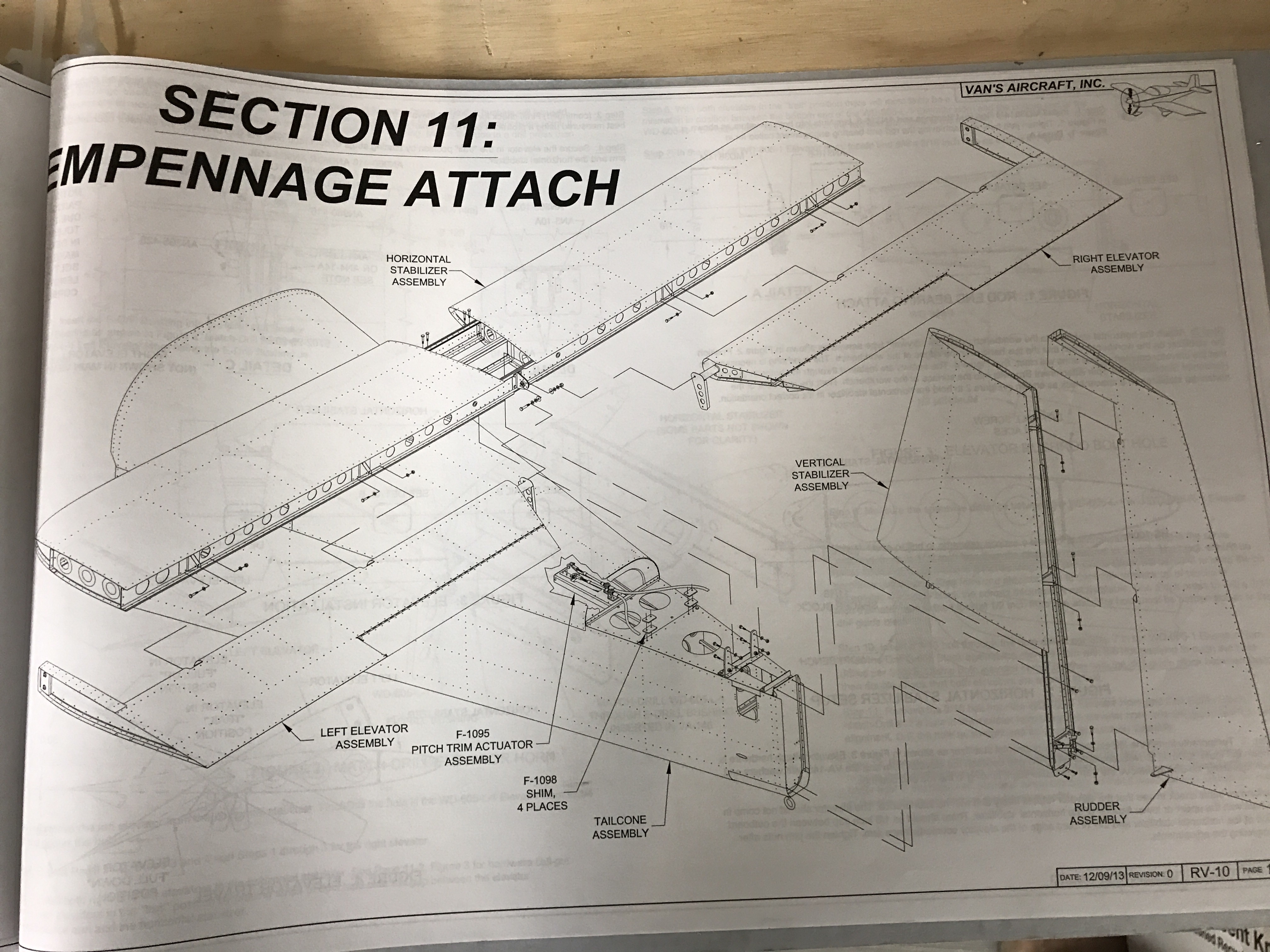
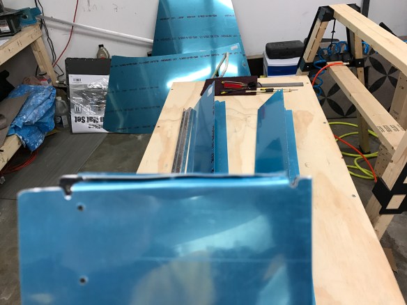
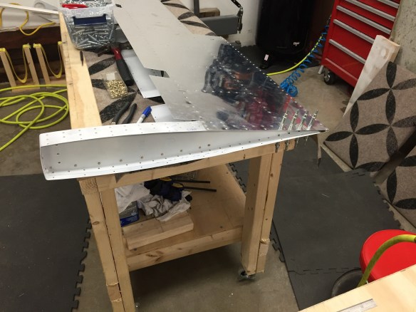
The first steps are to attach the elevators to the Horizontal Stabilizer and making sure you have sufficient travel up and down with no binding.

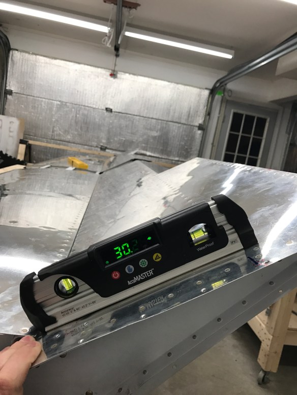
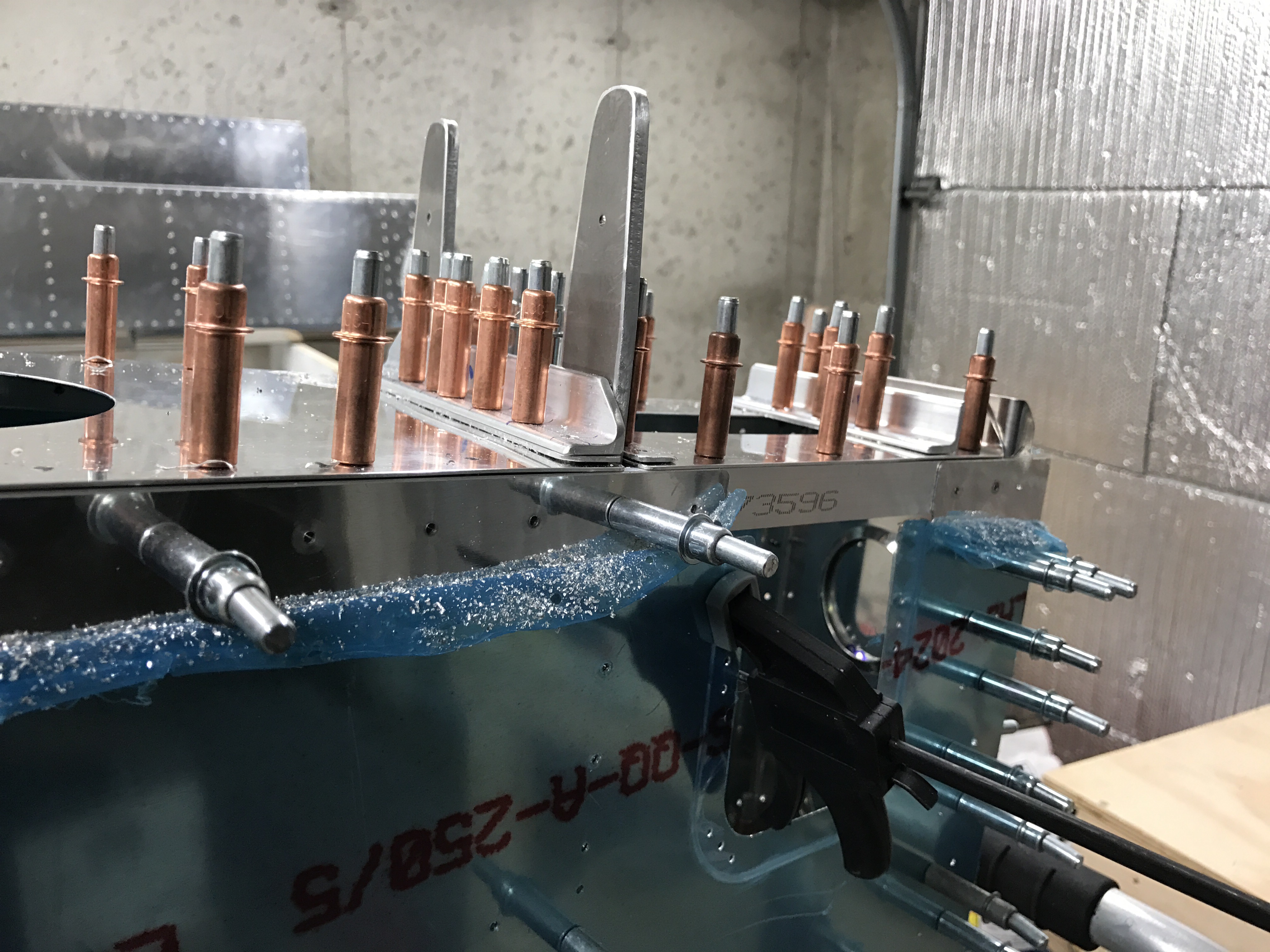
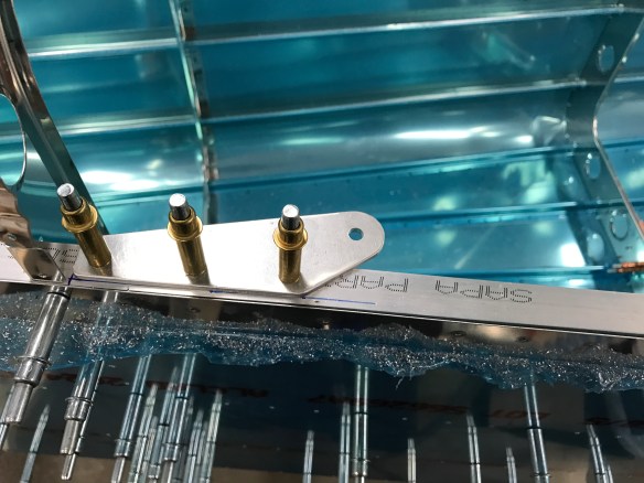
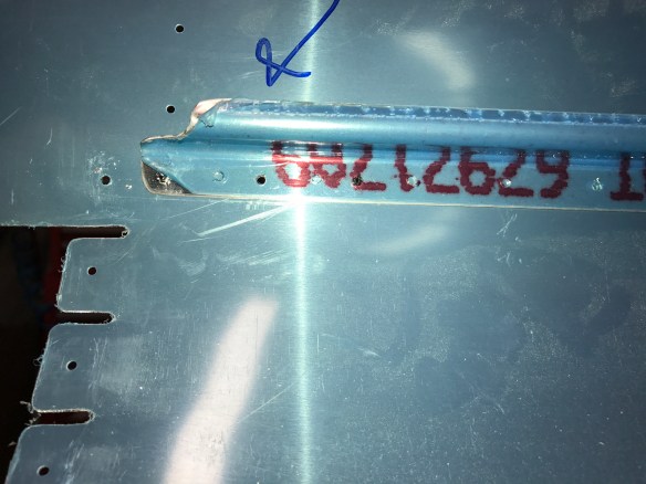
Measuring the UP direction.

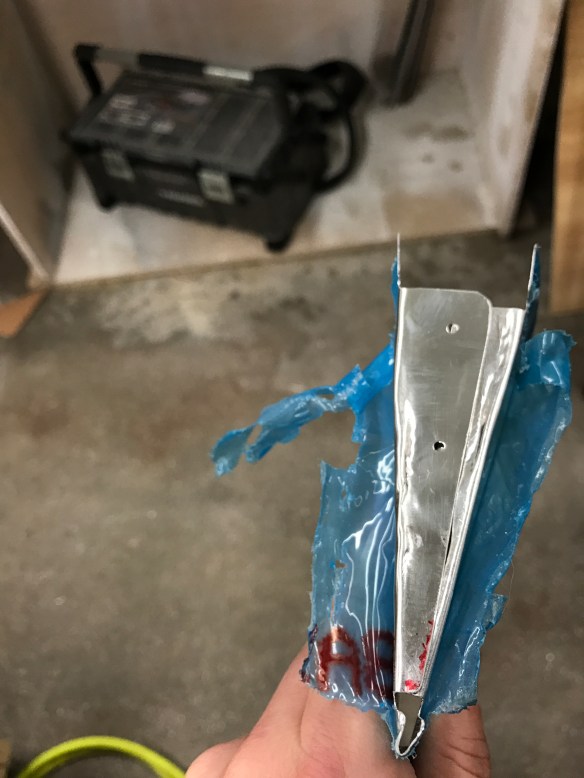
After drilling the Elevator horns and clamping them together. 

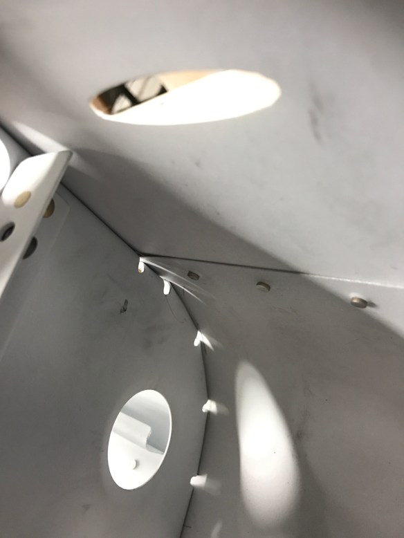
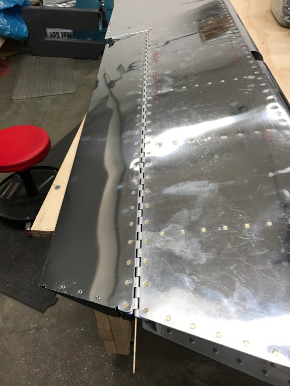
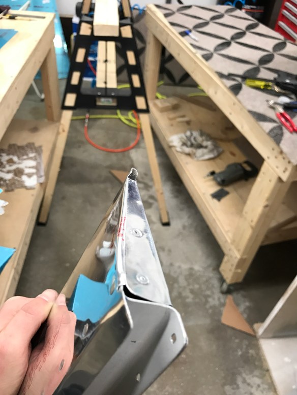
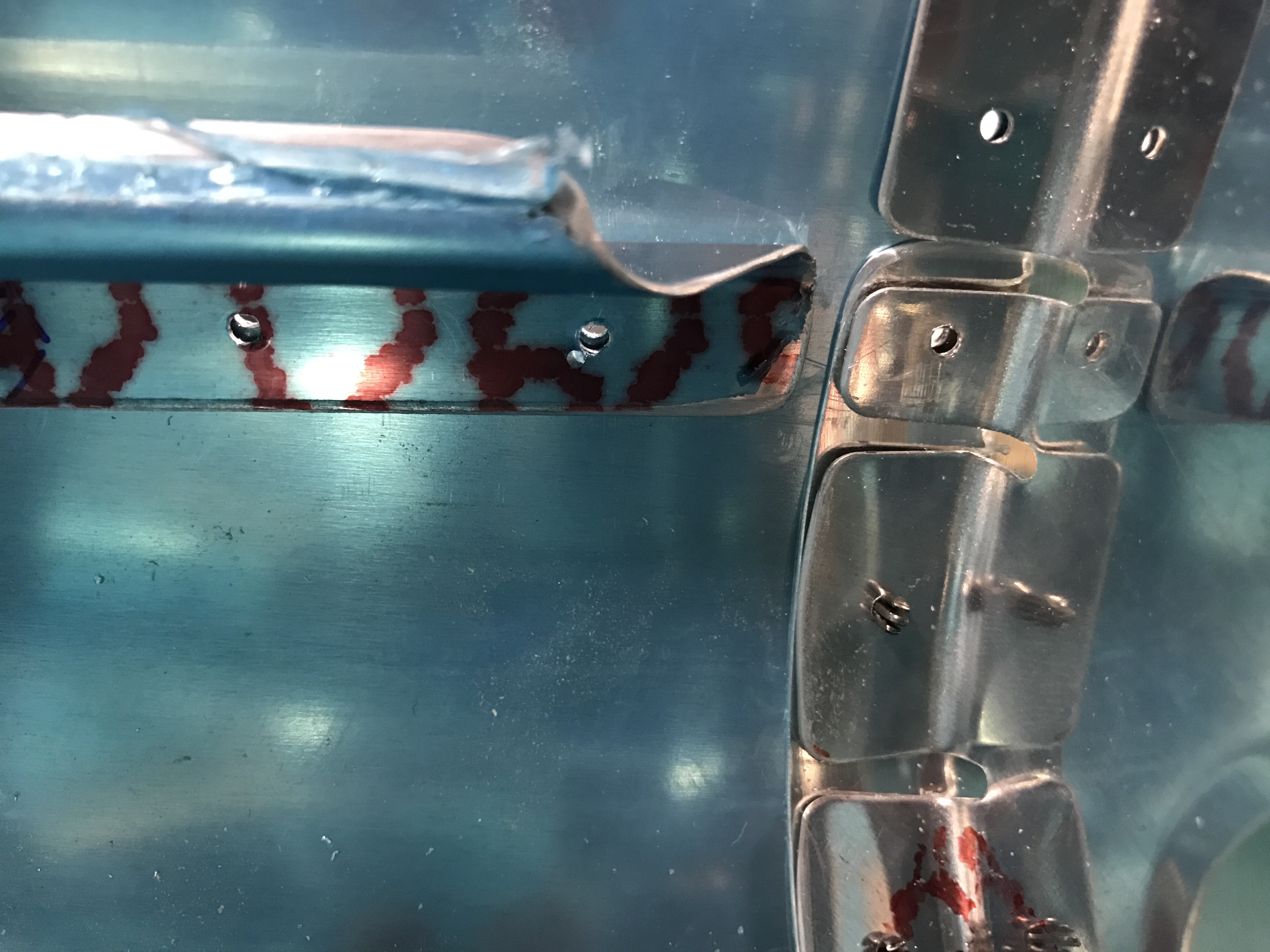
I then ran into a minor issue in that the gap between the left elevator and the horizontal stab wasn’t very even. The plans say there should be approx a 1/8″ gap along the entire length. I had a 1/8″ gap on the aft end, but it increased to 3/8″ forward. My right side was pretty close to perfect.

Uneven gap on the left side

Right side nearly perfect

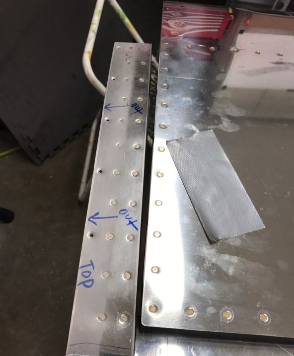
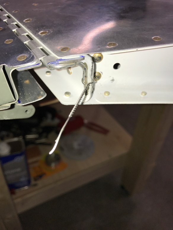
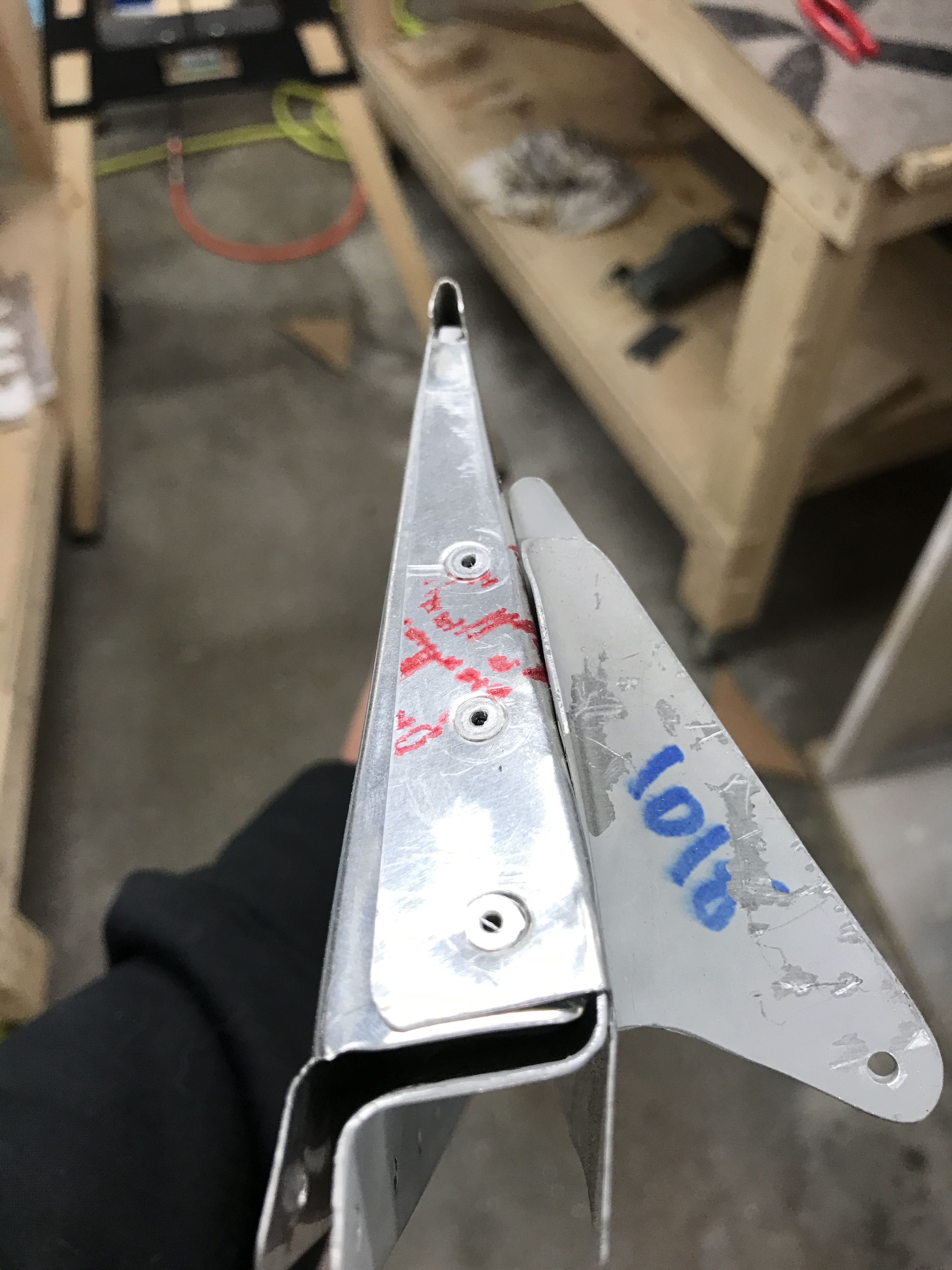
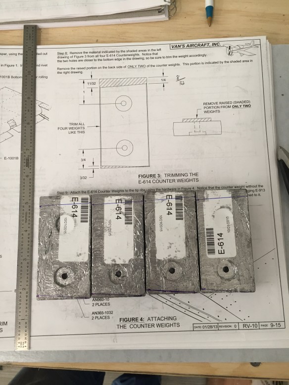
This gap isn’t a very critical thing, it’s more critical that the elevators are attached evenly to the Horizontal and that there is no binding through the entire range of motion with both elevators attached together. Still, it was pretty visible and annoying to me. Others have seen similar things, although maybe not quite as bad as me. Van’s suggested either 1) playing more with the rod end bearing adjustments or 2) drilling out 12 rivets (6 top and 6 bottom) and re positioning the elevator counterbalance arm as shown below. unnamed

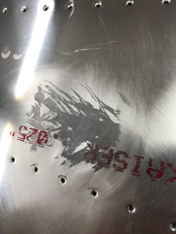
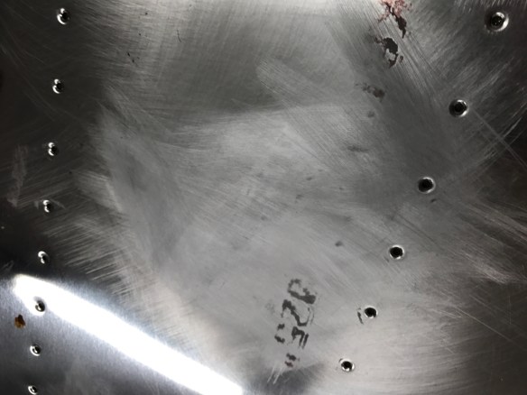
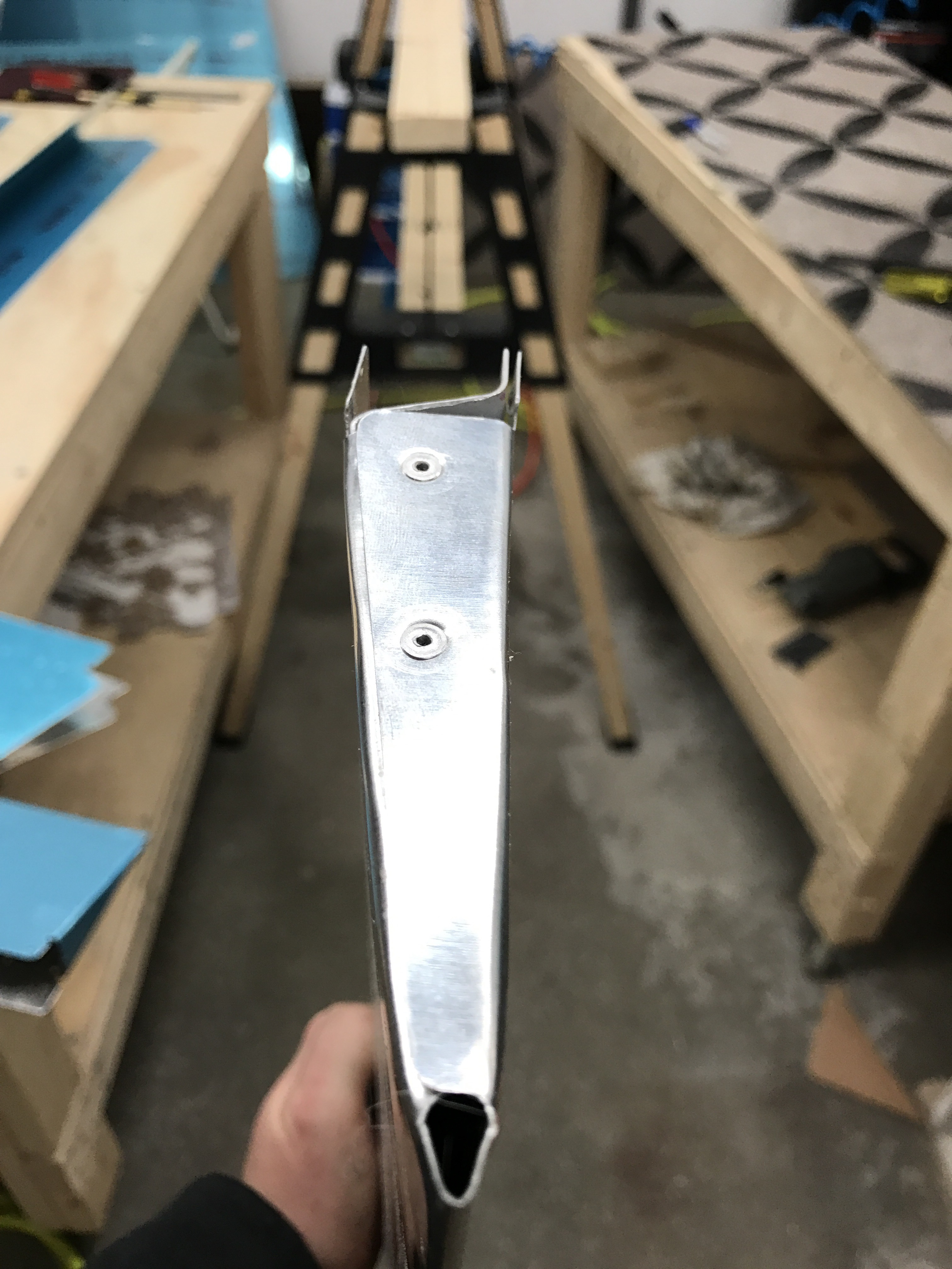
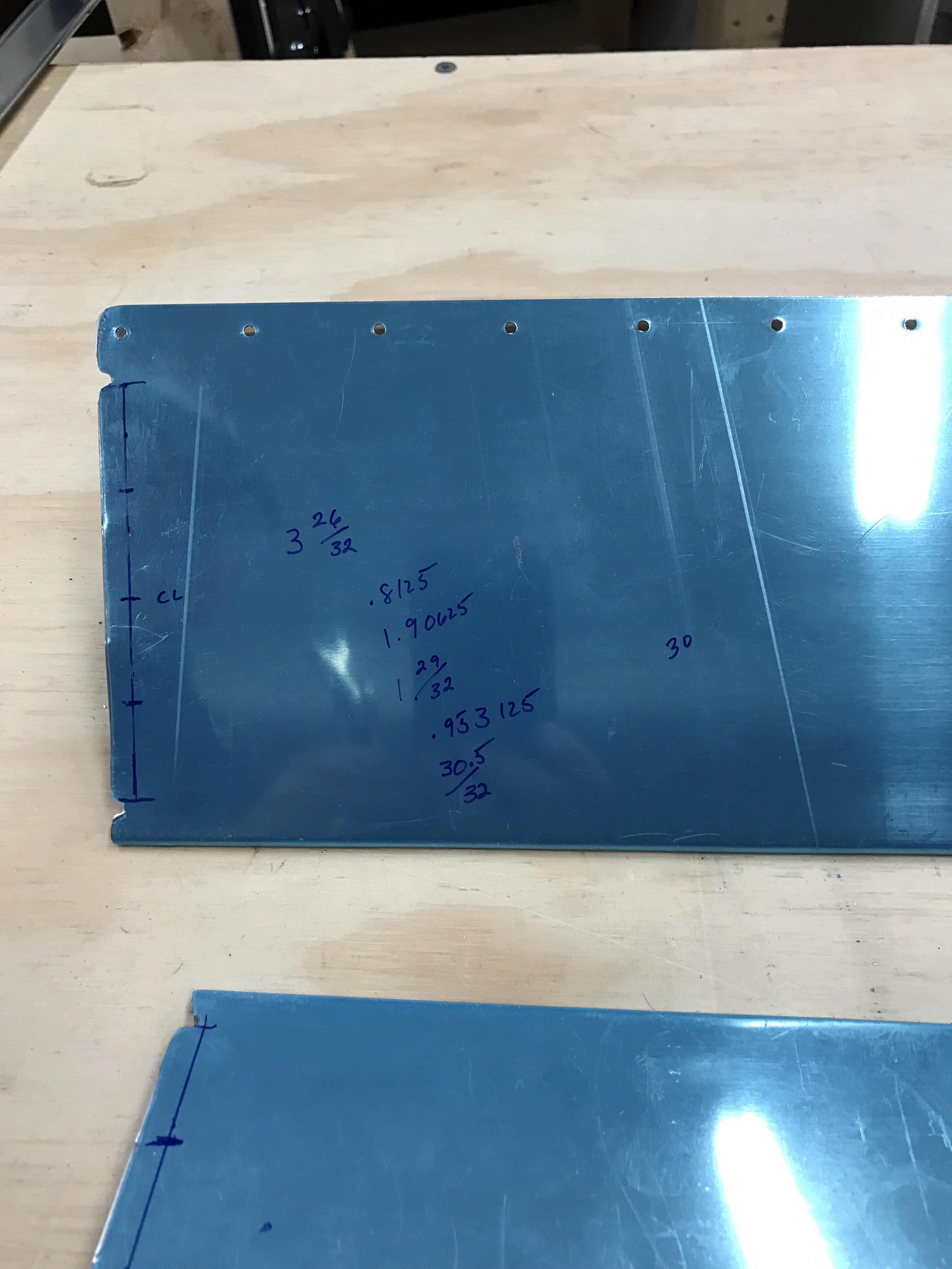
I played some more with the rod end adjustments, but wasn’t able to get the gap much better without causing it to bind up. So I decided to drill out these 12 rivets, push the counterbalance arm inward where I wanted it, and re-riveted those 12 rivets to hold that position. The results were much better! There’s now only a 3/32″ difference between the aft and forward ends as compared to 8/32″ difference before! Also it was mentioned to me that once you put the fiberglass fairings on, it may tighten it up a bit more by removing any twist remaining.

Much better!

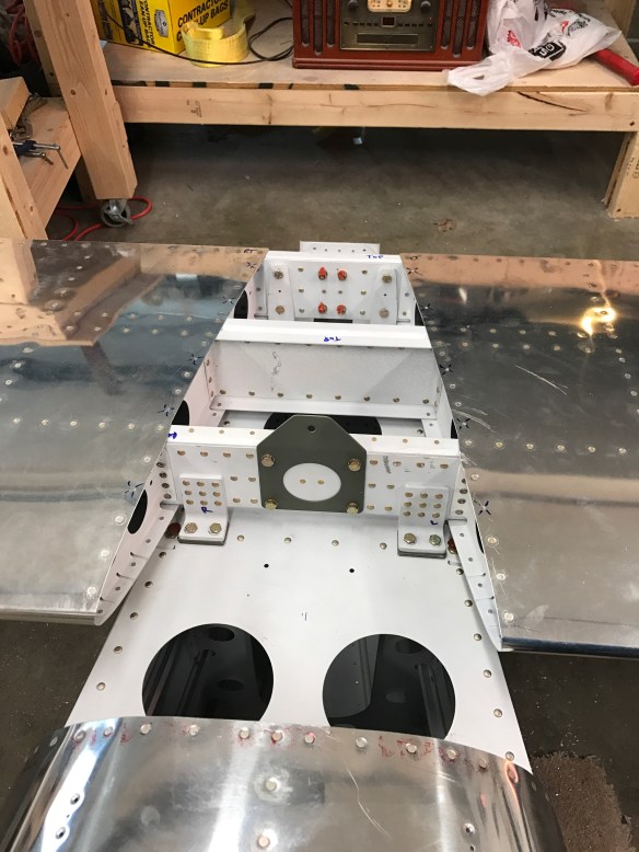
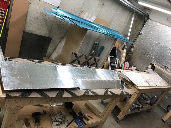
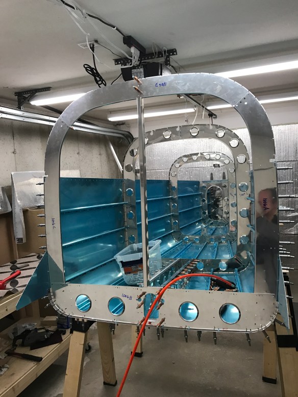
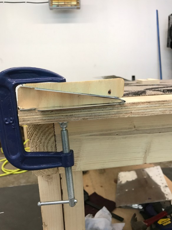
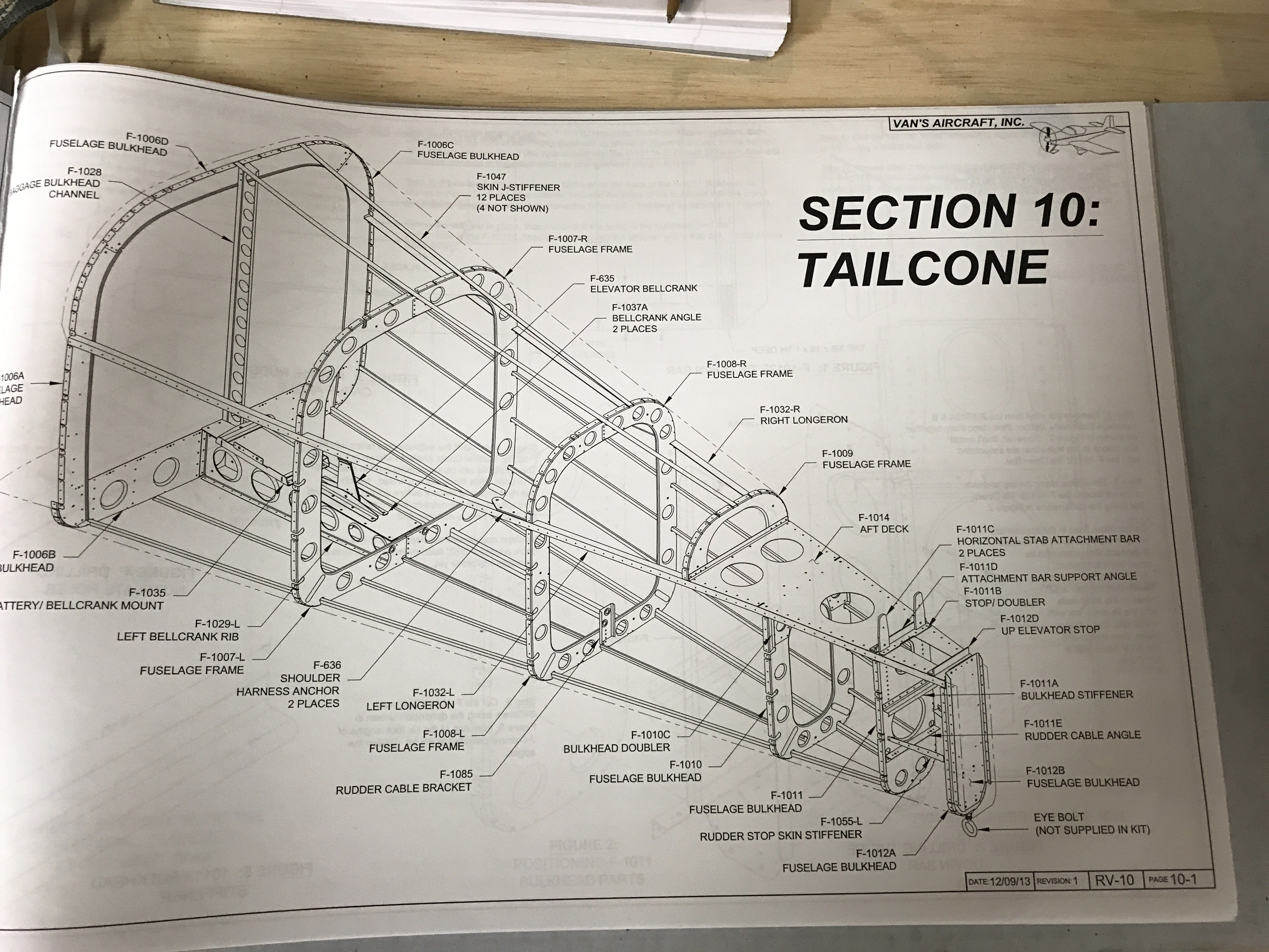
So with that behind me, it was time to make some shims and mount the horizontal stab to the tailcone.

Once mounted and partially secured, you cut a piece of 2×4 to wedge between the forward attach points and clamp it down to the tailcone. You then measure from a common center rivet on the tailcone skin to each corner to make sure the HS is square to the body. The clamps allow you to move the HS left or right and clamp it down in that position until you get it square. Took me a few rounds back and forth trying to get it as perfect as I could.

Horizontal mounted on tailcone with 2×4 and clamp to adjust squareness.

All Square, forward holes drilled and bolted.

The next steps were to mount the Vertical stabilizer, and drill some holes through the back of the tailcone, and then mount the rudder, much like the elevators.

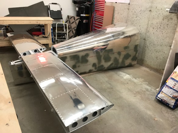
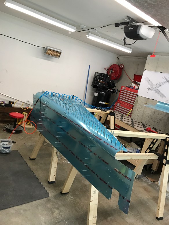
The end result is the realization that I really am building an airplane in my garage!

A few steps are left after this achievement. Namely I connected the elevator push rod and made some basic adjustments.

Elevator pushrod. Primer a little beat up prior to a touchup coat later on. 

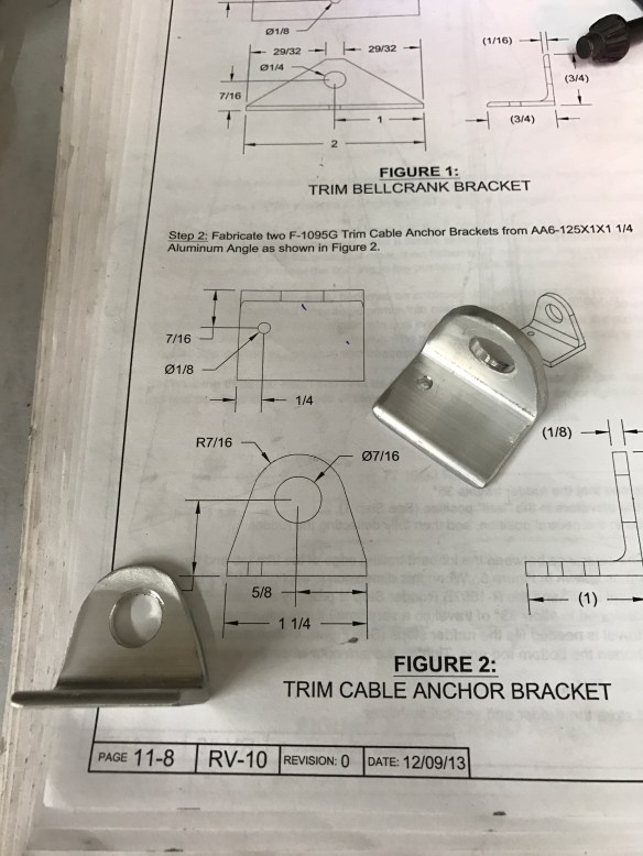
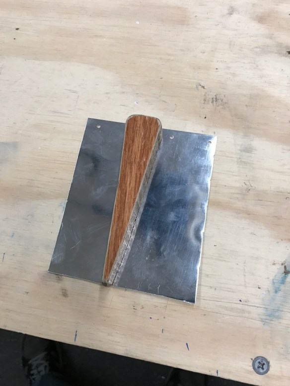
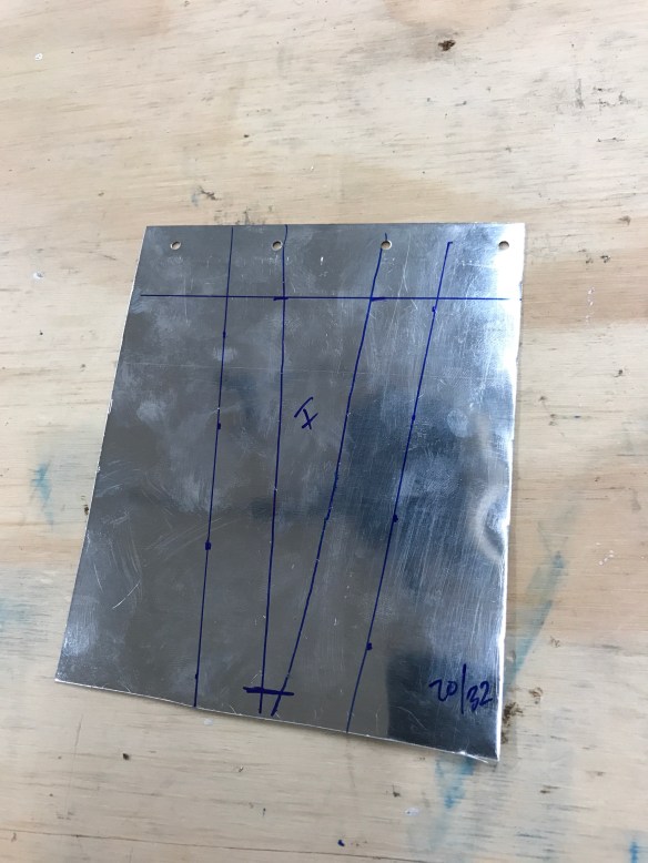
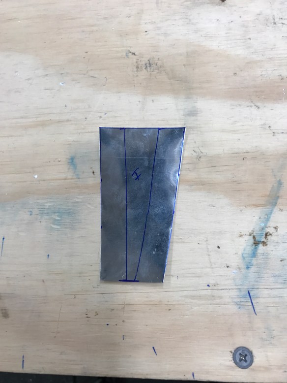
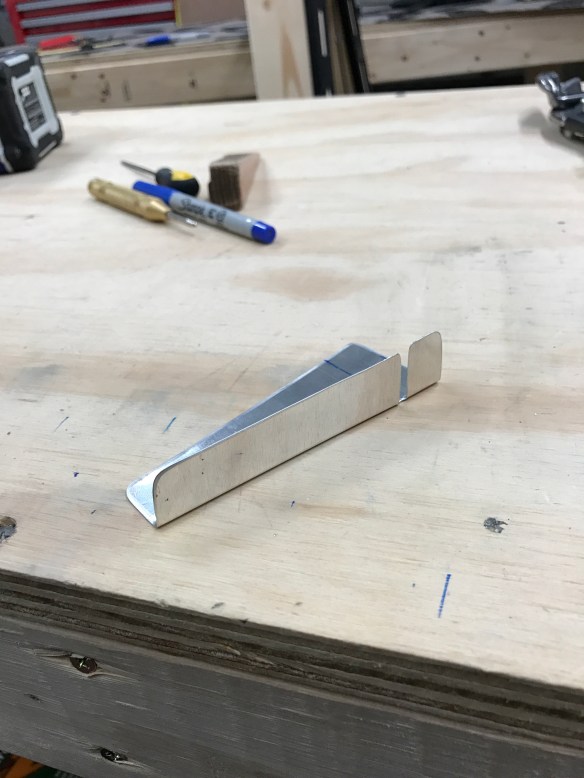
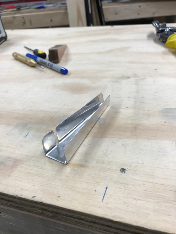
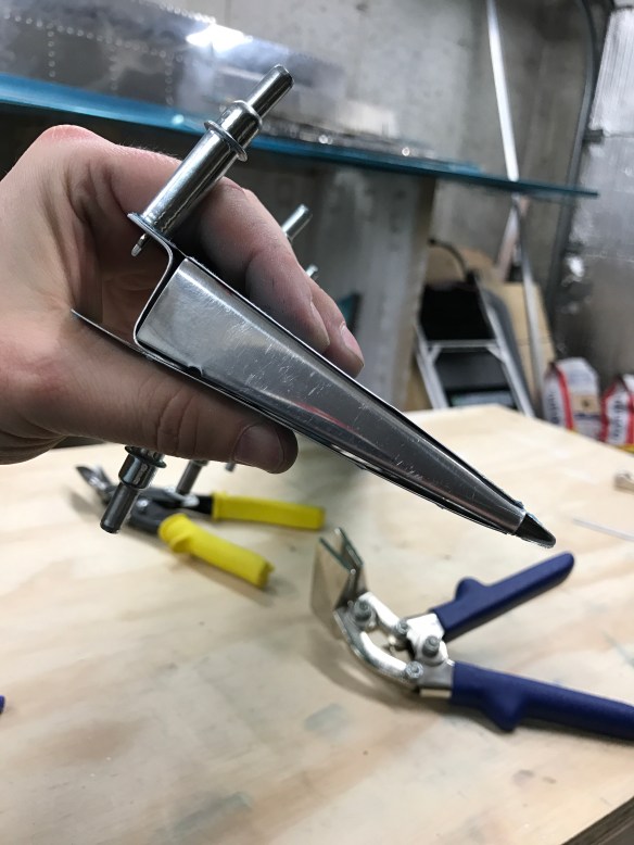
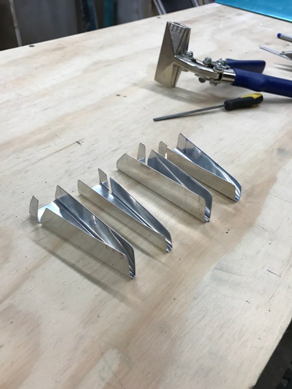
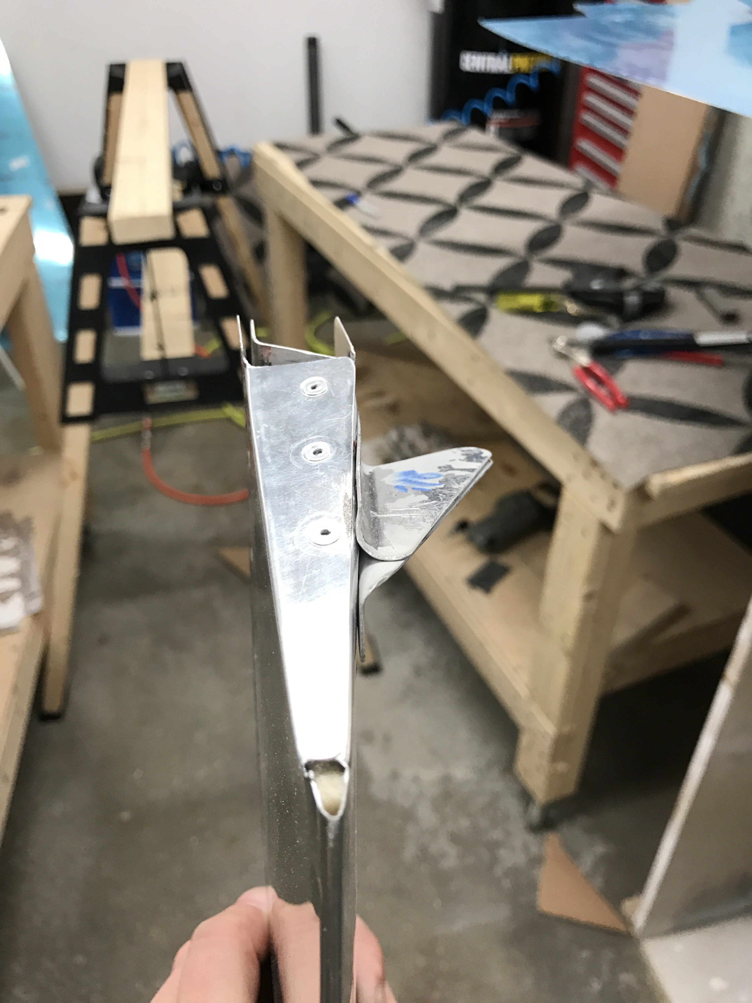
The last couple of items to finish up were to fabricate some brackets for the elevator trim bellcrank assembly.

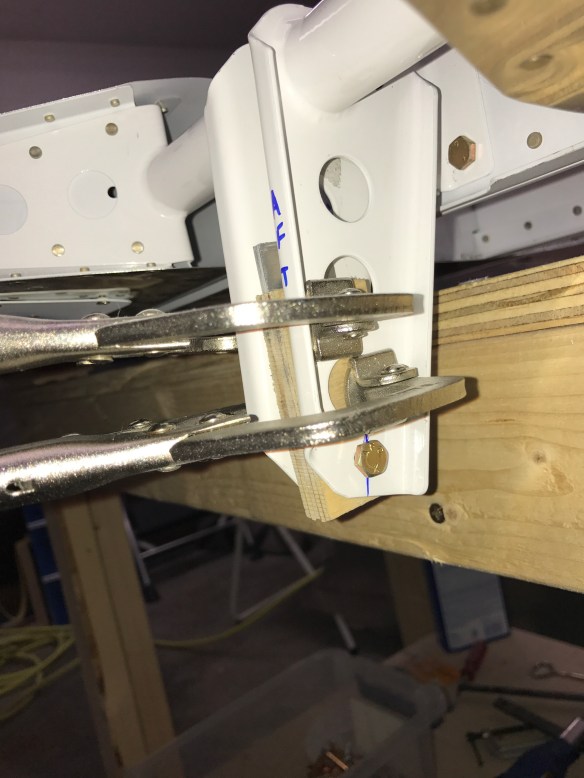
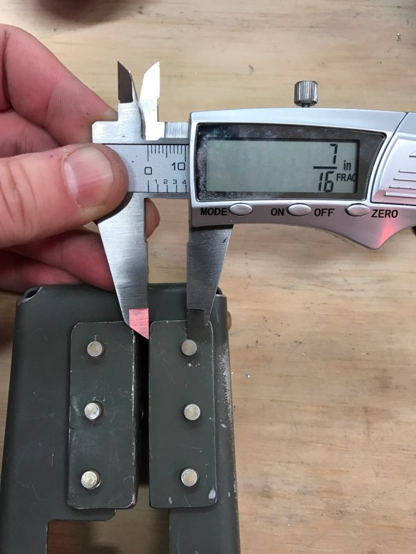
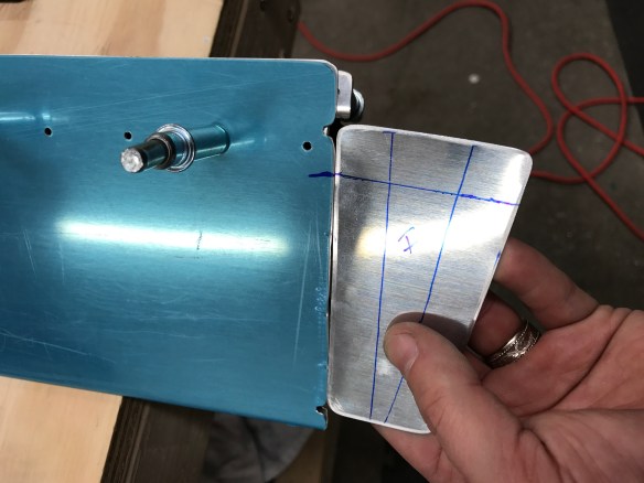
I did run into one issue, which I still have yet to resolve. There was no extra space between the bellcrank to put the washers called out. The plans are clear that thinner washers can be used, but I’m skeptical because I can’t even get a single washer in on one side without significant effort. There are washers available that are half as thick (0.016″ thick) and I have ordered them. There is a little side-to-side play with no washers installed, so maybe these will work. I will wait to get them to see if they will work.

No space to insert washers between the brackets and the middle bellcrank.

I double checked things, and I don’t think I messed anything up. The hold spacing is 7/16″ and the 2 brackets are parallel to each other.

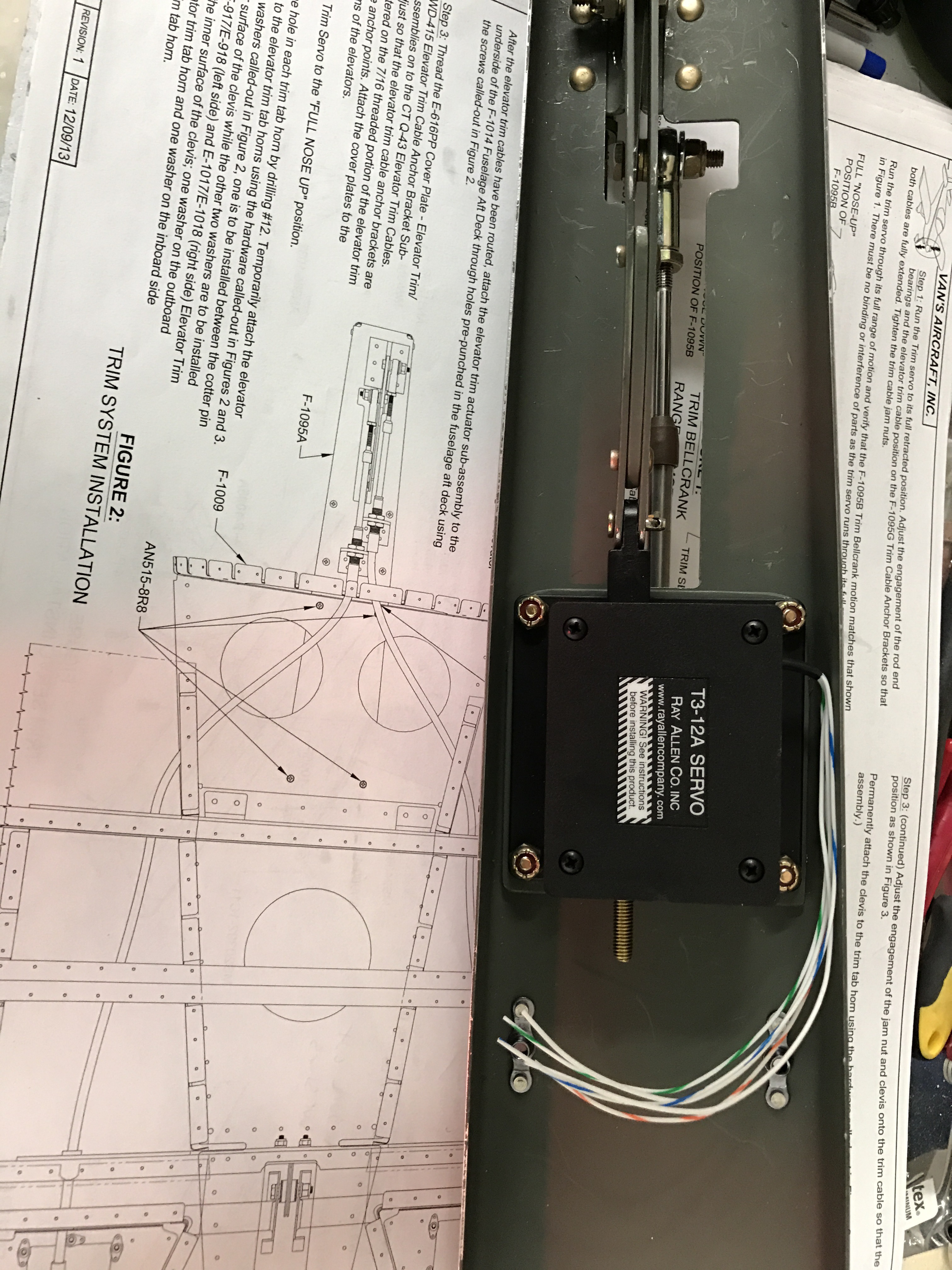
So for now I attached the servo and trim cable, but have left the adjustments for later.


Tailcone Progress

A bunch of progress since the last post.

An idea that I stole from Ed Kranz was to take some used carpet and cut out a spot for a back-riveting plate. Like him, I had to  shim underneath of the plate to make sure it sat proud of the carpet surface. The carpet allowed clecos to be inserted from the inside of the structure and poke into the carpet without disrupting a solid surface to rivet against. After a few sessions of adjustments, I finally got it just right to be a solid setup. This has made very hard to reach areas to rivet with just one person much more doable.

I assembled the right side first, followed by the left side, to keep the structure as open as possible for access to back riveting. One mistake that I made was getting the bottom aft skin on top of of the J-channel stiffener when it should really be between the outer skin and the stiffener.

Bottom Skin between J channel and flange tab.

A slight gap created by the incorrect stackup.

I had to drill out about 17 rivets to pull the bottom aft skin out and correct. In doing so, I buggered up one hole by somehow tearing the dimple.

I asked Van’s how to deal with this issue, seeing I don’t have edge clearance to just drill a new hole. They said to stop drill it and make a backing tab to put behind the flange tab.

Stop drilled with a 3/64″ drill

New backing tab curved slightly to match

Good fit

Some other pics of the progress by the end of the weekend.

Tailcone Priming and Final Assy. Started

Boy there are a lot of parts to prime in the tailcone. It took several sessions to finish all of the priming. I started by doing the skins, and then 2 additional sessions to do the remaining smaller parts. On most parts I take the blue protective coating off of the part the first time I start to work on it. With the skins, I’ve been leaving the outer blue protective coating on until later in the process to help prevent scratches. Upon removing the coating from the side skins, I found a bunch of surface corrosion starting. Nothing too terrible, but enough that some spots took a lot of elbow grease to sand off. I mostly used a maroon scotch brite pad, but a couple of stubborn spots needed a little fine sandpaper to go a bit deeper, followed by more scotch brite to get it completely off. I then sprayed the areas with some rattle can self-etching primer to help protect it for now.

Lots of these corrosion spots on the side skins

Mostly all gone

This picture will give you an idea of how many spots there were to deal with.

Pile ‘O Primed Parts

Initial Couple of Parts Assembled

Bulkheads Riveted Together

img_8082

Getting Ready to rivet skins to stiffeners


McRiblets

I spent a few hours today finishing the bend to the new elevator trim tab skins and fabricating small ribs (riblets) to close out the ends of the trim tabs.

I think they came out really well. The first one I did came out fine, but was a bit of a test on exactly where to bend on my marked line to get the proper part width/flange length. I then was able to bang out the 4 riblets that I needed to make. Two outboard and two inboard riblets. The outboard riblets somewhat interfere with trim tab horns, so I made the flanges a bit longer to share holes and ensure proper edge distance.

I took the following pictures to document the process.

Started with a wooden wedge (oak) that I had previously made when trying to bend the tabs per the plans as a template against scrap trim tab skins.

Traced the outline of the wedge, marked the top and bottom cuts, and make a 20/32″ outer mark for the flange width.

Cut along the outer lines with snips.

Marking the position of the spar on the bottom skin and transposing that line to the riblet

Using a punch to locate the hole to be drilled

Drill a hole to serve as the relief for the flange separation

Snip out the metal on the tangent lines of the circle creating a separate flange piece that can be bend in more to accommodate the extra layer of metal of the spar.

Bend along the marked lines with a hand seamer.

First flange bent

Spar flange bent

Done!

Pretty good fit!

All 4 riblets completed. I used a 20/32″ flange for the inboards and a 28/32″ flange for the outboards to allow for hole edge clearance.

Marking out new holes that I will drill in the skins to rivet the riblets in place. 3 new holes will be added between the notches in the skin.

All-in-all, I’m very happy with how they came out. These were really the first true part that I’ve had to fabricate from scratch on my own. It really wasn’t as hard as I had anticipated, and it’s satisfying to see it come together. I can tell already that I’ll be very happy with how this turns out compared to my barely acceptable bending of the tabs.

Upper Tailcone and Elevator Trim Tabs take 3…

Since the last post, I’ve completed putting together the tailcone structure and match drilled everything. I’ve subsequently taken it all apart and deburred all holes and any remaining edges.

Looks like an airplane part!

Rear Seat Belt Anchor Point


Pile of deburred parts

In the meantime, I wasn’t completely happy with how my elevator trim tabs came out, so I got new parts to re-do them. The 2nd time went worse than the first.

The goal here is to bend the tabs to close out the ends of the trim tabs. It seems like it should be relatively easy!

elevator-close-outs

I didn’t have trouble bending the tabs on the skins, but these have given me trouble.

After messing up the first bend of my second attempt, I went off to do some reading on VAF. It seems lots of other have also had trouble with these tabs, so I guess it’s not just me. I also realized that I didn’t use any adhesive on the blocks so they moved slightly while attempting to bend the tab. Once I used some double-sided carpet tape, the next attempts went a little bit better. Probably passable, but I had already managed to crack the skin during my first bend.

Badly dented and cracked skin

Another attempt with tape. Better. Probably passable, but not the greatest.

Wavy!

The first set of trim tabs I attempted are shown below.

Bit of a buldge

Below is yet a 3rd set of new skins for the trim tabs. After doing some reading, I’ve decided to do what others have done, and that is to cut off the tabs and fabricate small riblets to put on the ends instead. It might take me a few tries to get those correct, but I have lots of scrap trim tab metal to work with.

3rd set of skins 😦

showthumb-php

Plan to fabricate something like this instead.


More Tailcone

Making decent progress on the tailcone. I’ve got the lower structure completed and match drilled. Starting to work on putting the top skins on now. Getting close to taking everything apart to do some massive deburring.

I’ve also placed my order for the Quick Build Fuselage. Initially, I was thinking I would slow build this part, but have since decided to order the QB. I didn’t do it the standard way in terms of ordering both the QB wings and fuse at the same time, but that should be fine. It also helps spread out the money outlay a little bit.

My wings are currently scheduled to be shipped in January. Fuselage in April. I should have plenty to keep me busy between now and January. I still have to finish the tailcone, attach the entire emp together, and do the fiberglass fairings. That should keep me busy until the wings come. Then I’ll have some stuff to work on with the wings prior to getting the Fuse a few months later.


Starting to put the bulkheads on the bottom skin.

A video of me match drilling one of the bottom J-Channel Stiffeners.

Right side skin attached

Center line on J-channel stiffeners showing through the skin holes to make sure of proper edge clearance when drilling. 

Then I realized I had made a mistake. I had aligned one of the J-channel stiffeners to the wrong starting hole. Oops.

I had actually discovered it when I was checking to make sure that the aft end of the stiffener was captured by the tab in the bulkhead. Clearly it wasn’t.

So what I did was to slide the stiffener down and align the first drilled hole with the hole it should have aligned to. The end result was I had to drill extra holes almost equally spaced between the existing holes along the entire length of the stiffener. This worked well. I ran it by Van’s and got their blessing as well just to be sure the extra holes wouldn’t compromise the stiffener too much.

Shows the first hole in the stiffener aligned properly now. You can see new holes need to be drilled about equidistant between the existing holes in the stiffener. 

First couple of extra holes drilled. 

Starting to look like a real airplane piece

View from the front end looking back.

Aft deck on and aligning the longerons with clamps

img_7921

Flipped on its side to match drill the bottom holes


Start of Section 10 – The Tailcone

The elevators are done with the exception of the trim tabs… Well the first iteration of the trim tabs anyways. The main mistake I made on the trim tabs was bending the close-out tabs on the end too close to the reliefs in the skins. I misread the directions and thought I was supposed to put the supporting wooden blocks 1/32″ to the inside, when really it was in the opposite direction. The end result is some bulging as you approach the ends of the tabs because the tabs are too long. Not real terrible, but I’m just not happy with how they came out. So parts are on order to build new ones, which won’t take more than a few hours to complete.

Testing the trailing edge bend of the trim tabs

Bending the close-out tabs (wood blocks placed too far inboard)

Trim tab hinge in place and match drilled

Proseal curing…

So for now, I’m on to Section 10- The Tailcone.

Rear tie-down anchor point

Tailcone floor plus lots of parts prepped in the background

Elevators getting close and a new compressor.

I bought a new compressor to give me some more capacity and be a little quieter seeing it’s in the garage with me. I decided to get a 2 stage, 60 gallon model from Harbor Freight. It refills very quickly now and is much better when running the air drill or spraying primer.

img_7738

New Compressor

Since the last post, I’ve made a lot of progress on the Elevators. Below are some pics documenting the process.

I had a nice day to move the priming outside for this round. I used an old grill top from my pig roaster that I never use to provide a better backdrop for the spraying. Previously, smaller parts would really move around, flip over, etc… I figured it was because I was spraying against a hard surface and not something that the air from the spray gun could blast through. Happy with the results. The setup is shown below with all of the parts laid out (minus the skins)

img_7740

Priming parts outside for the first time.

Various pictures of initial riveting of the spar and spar stiffeners, trim access stiffener and nutplates, stiffeners back-riveted to the skins, and pop riveting the ribs in some tight quarters.

A video of me using the special RV-10 Emp bucking bar that I bought with my toolkit to rivet the rear spars

Most riveting done.

img_7800img_7799img_7798

My rudder trailing edge came out okay, but I wasn’t 100% happy with how the joining of the skins came out using the VHB tape. Seeing the foam ribs are attached to the skins with Proseal, I decided I would also use the proseal for the trailing edge as well to see how it goes and compares with the VHB.


img_7801

Foam ribs with paper templates attached. Ready to cut.

img_7802

Messy stuff

img_7805

Both Elevator Trailing edges done

I also decided to use the steel bars I have and match drill them to the trailing edge holes so the clecos end up holding everything tight to a straight bar.

img_7803

Right Elevator set and ready to spend a few days curing

I then spent some time riveting the trim covers and trim attachment brackets together, along with marking and trimming the counterbalance weights.


img_7806

Now to wait a few days for the Proseal to cure. In the meantime I’ll start working on the trim tabs.