Fuel System, Rudder Pedals, Goodies

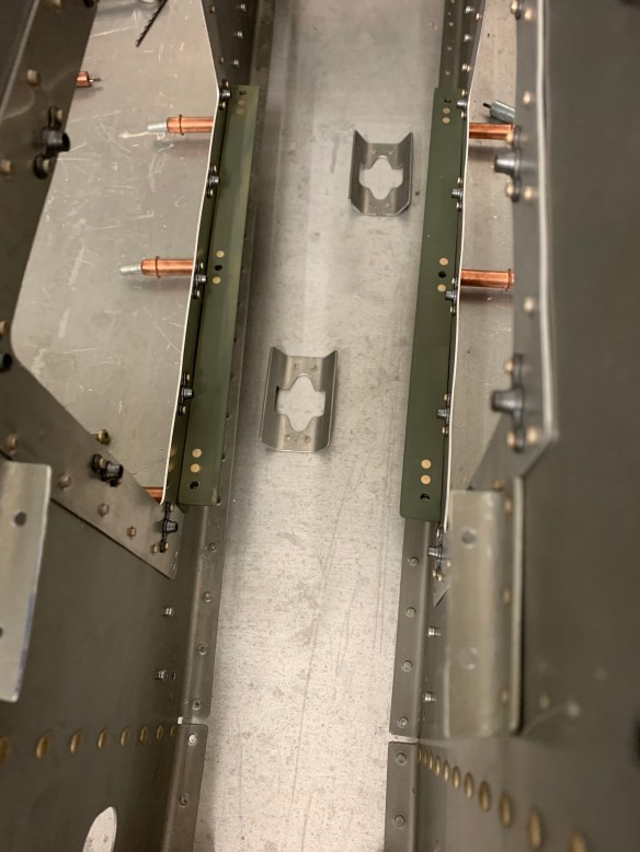
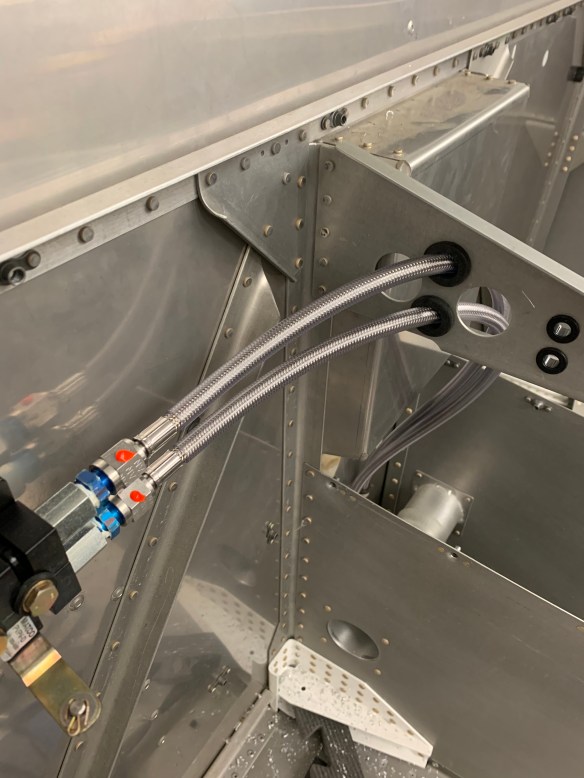
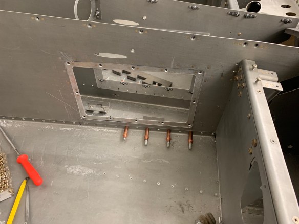
I needed to decide on whether to put the pre-filters for the fuel lines under my seats or in the tunnel. Tom at TS Flight Lines had suggested 2 methods. Either a single pre-filter and post-filter mounted above the fuel pump module, or have 2 pre-filters one for each supply line under my seats. In either case, the post-filter would be in the tunnel. Advantages of under the seats are that less room in the already tight tunnel would be taken up. Some also may argue ease of maintenance, although I’m not 100% sold on that. The cons are that attaching the pre-filters to the tunnel bulkhead fittings as Tom leaned towards (which allows for a single hose assembly from the fuel tanks to the pre-filters) was causing lots of extra work. The pre-filter in that location interfered with the systems bracket that holds the lines in place off the bottom skins. I was going to have to cut that partially out to make room for the filter and also adjust the top part of the bracket too to fasten to the modified lower half of the bracket.

Advantages to filters in the tunnel are: there is only 1 pre filter module (less cost) and less modifications, saving time. The main downside is that it takes up more room in the tunnel.

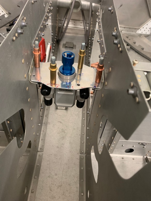
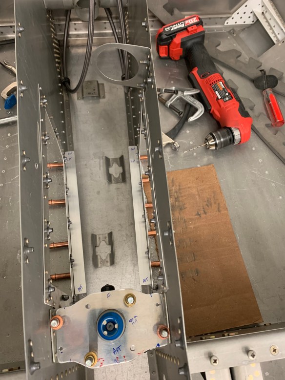
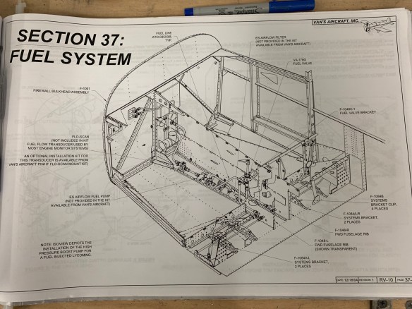
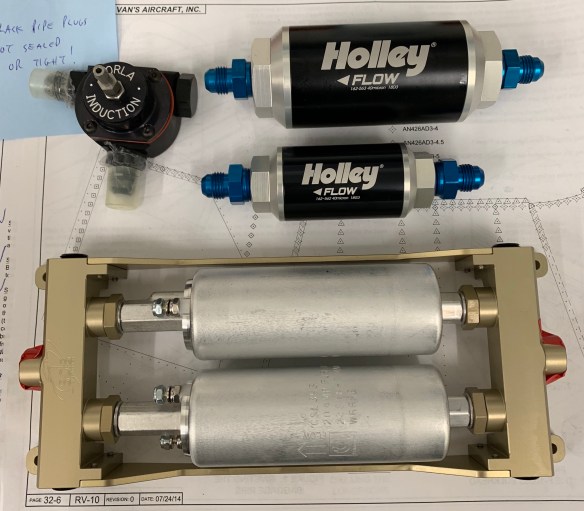
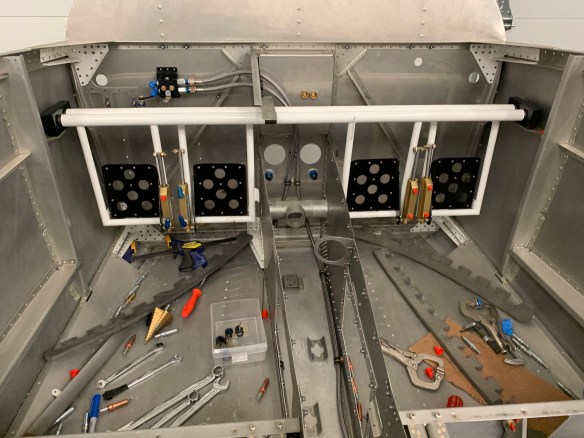
Below are pictures of the 2 methods:

Method 1: Under the seats

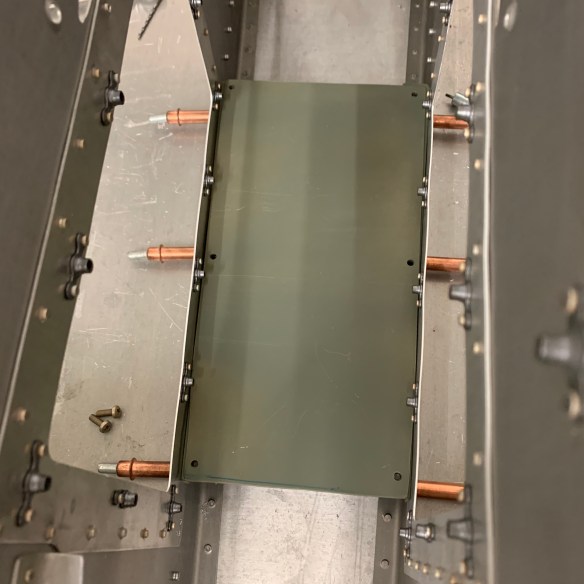
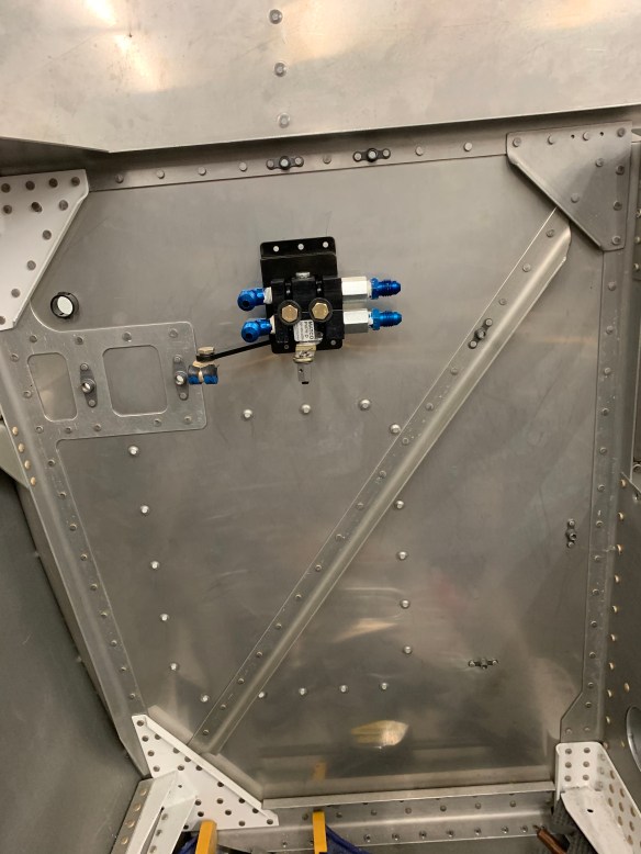
Method 2: In the tunnel as part of the pump module assembly (Adel clamps to hold it together are missing here)

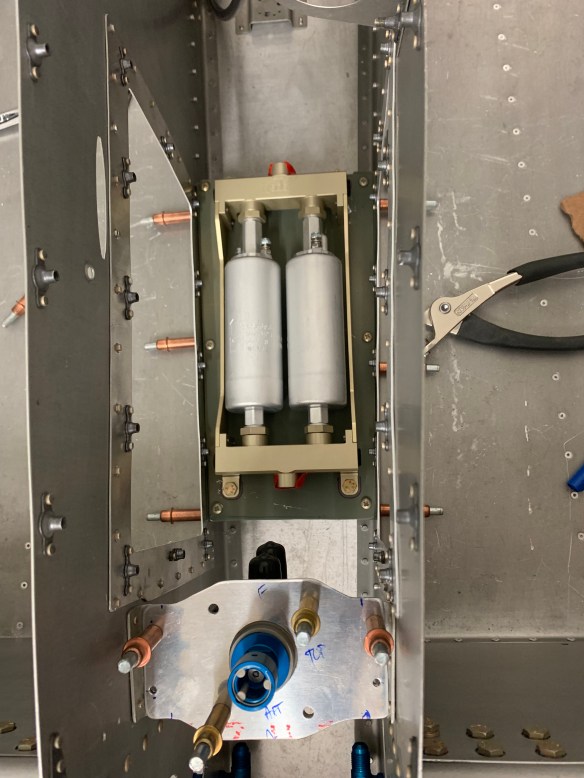
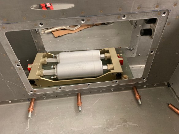
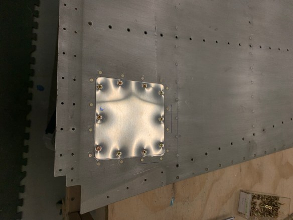
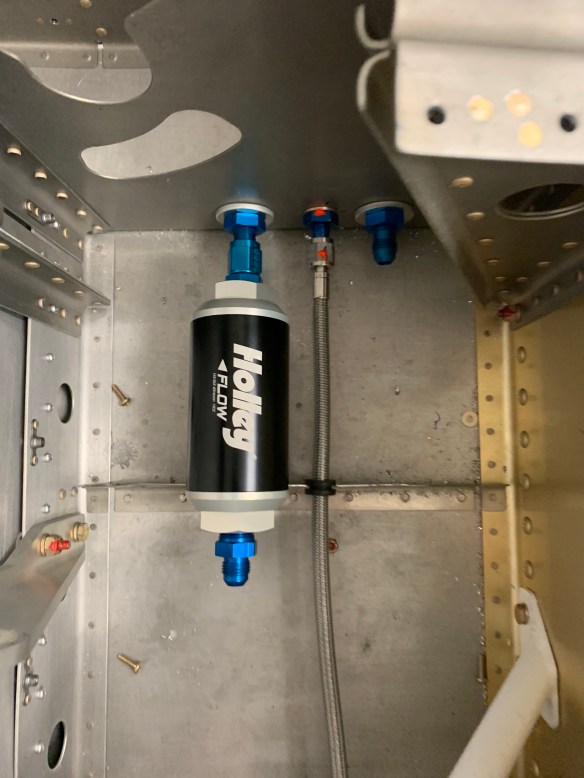
I ended up going with method 2. With this method, the pump module will actually be installed backwards in the sense that fuel flow will be going forward to aft (or top to bottom as shown in the picture above as the firewall would be towards the top of the picture). The idea here is a hose will connect the valve selector to the pre-filter on the left. Flow through the pump module and into the post-filter on the right. Then a hose will connect from the output of the post-filter to the firewall fitting to the engine. I liked the idea of a self contained unit, which required less hacking of the existing structure to make it work, and seeing I made the aluminum plate that the pump module sits on removable with 6 screws, maintenance should be as easy as removing 2 hoses (in and out) from the filters, unscrew the plate, and remove the whole assembly to work on it on a bench.

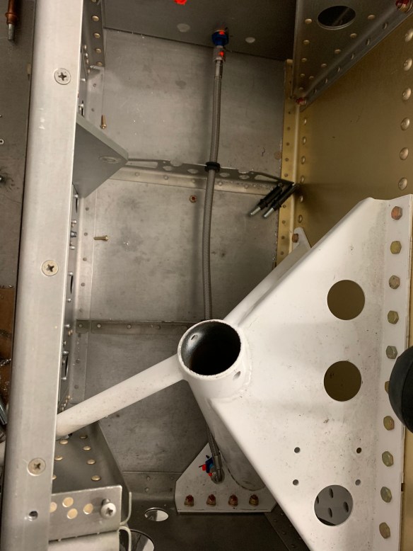
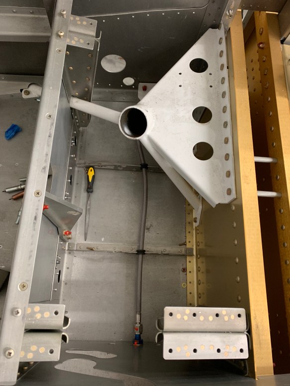
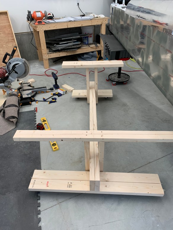
I then ordered my fuel line hoses after making that choice. In the interim, I started working on the rudder pedal section of the plans.

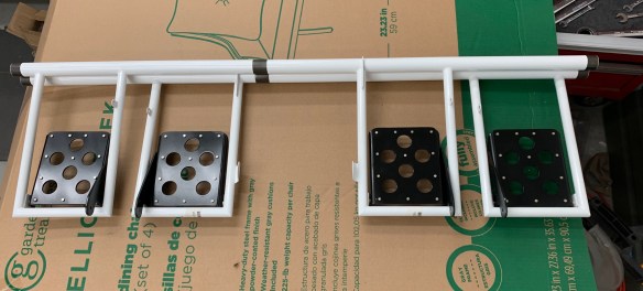
I prepped, primed, painted, and riveted the pedal assemblies, then attached them to the powder coated arms that span the width of the airplane.

I then attached the master brake cylinders to each pedal and inserted the fittings into the cylinders. Note a few are missing here in this picture. One of the pitfalls of going off plans. Seeing I’m using the flexible lines, I didn’t have enough AN822-4D fittings for all the holes, as Van’s provides some brass fittings which are intended for their way of doing the lines. Seems every time I turn around I need to order something new from Aircraft Spruce… Guess I’ll keep them in business.

Rudder pedal assembly in place temporarily

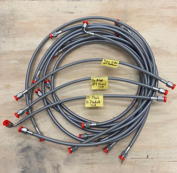
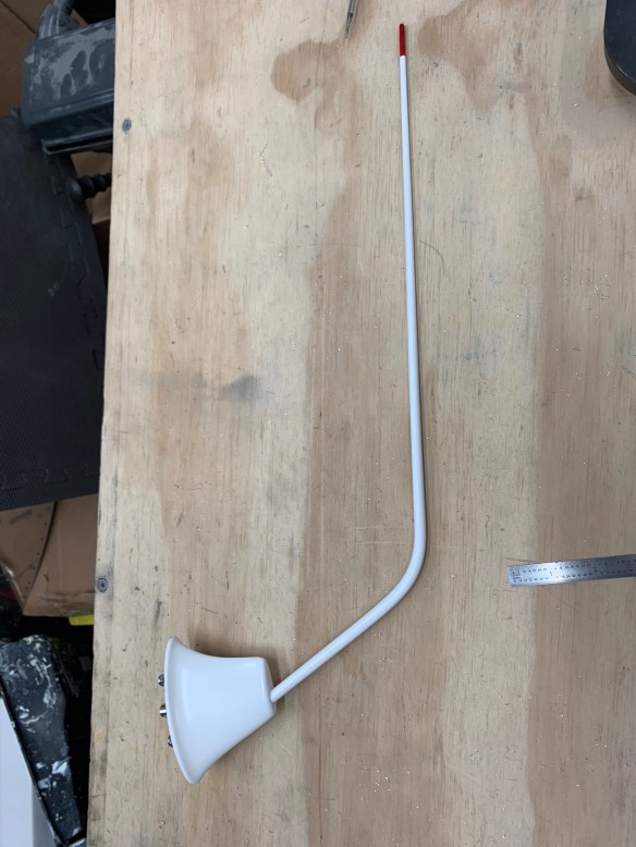
Some time away from the shop on a long weekend away in Kansas, and a bunch of items came in. My fuel lines, and a bunch of stuff from Aerosport including rudder pedal extensions, throttle quadrant, carbon fiber center console, and a NACA vent controller for controlling air to the overhead console vents.

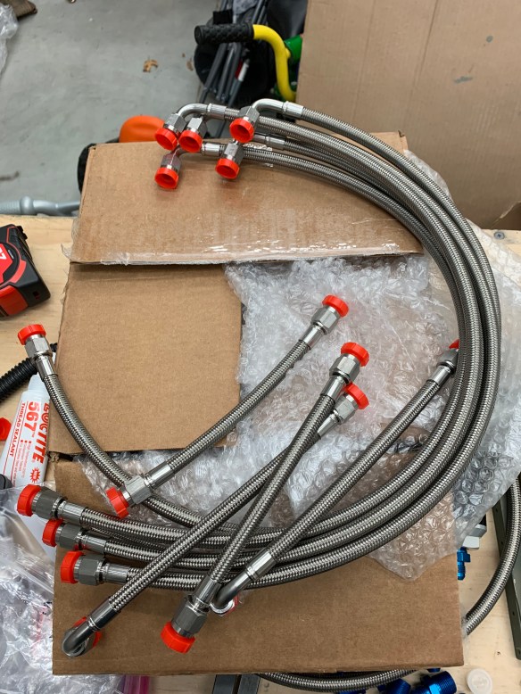
Fuel lines! (all except 2 which I need to measure for)

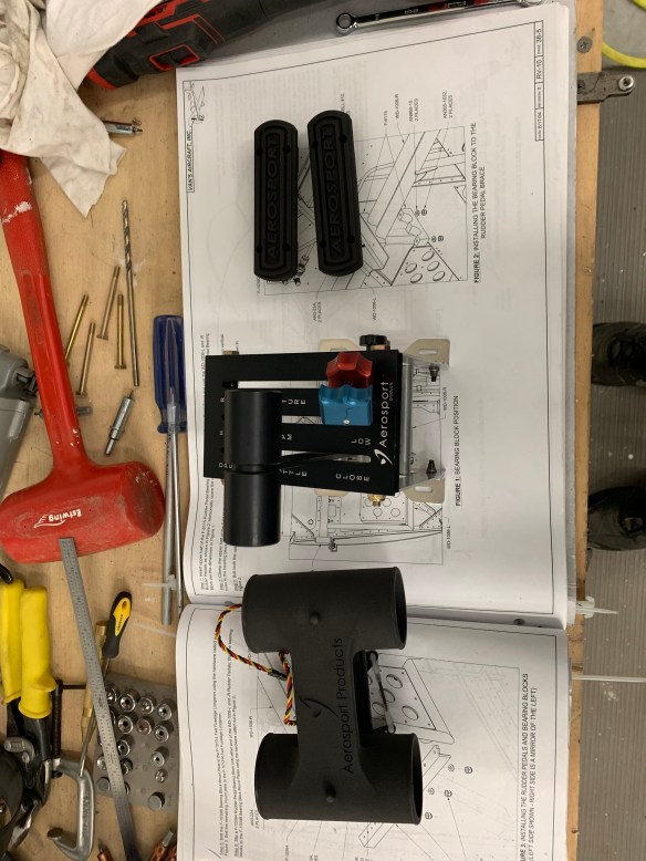
NACA vent controller (bottom), Throttle quadrant, and rudder pedal extensions

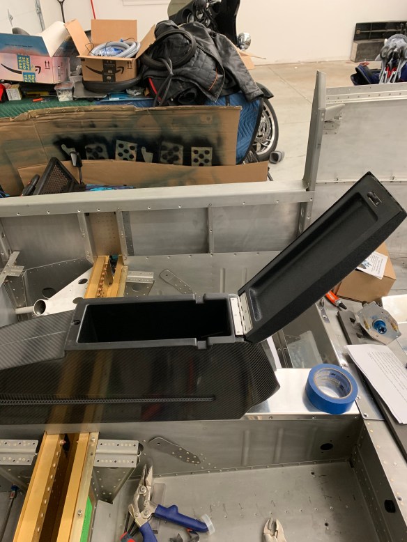
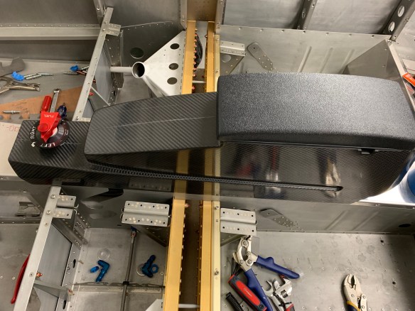
Center console in approx location.

Fuel selector placed in approx location between the seats

So for now it’ll be back to finishing up the fuel system before completing the rudder pedal section.

Fuel SystemUpdate

More progress being made on getting the fuel system components in place so I can measure hose lengths that I’ll need. Andair Fuel selector is now mounted in place.

With that done, I then moved on to fabricating two 11″ long angles to mount the fuel pump module on along with a piece of aluminum sheet cut to span the angles.

Looking down the tunnel at angles added

Sheet cut to size

Fuel pump in place

Then while waiting for parts to dry from priming, I went ahead and put a new hole in the firewall for the return fuel line. It’s a mirror image of the hole for the fuel supply. I marked the location based on the existing hole and then marked an “X” to drill from the approx. center. Happy with the results.

Then I riveted nut plates onto the angles to accept six #8 screws, clekoed them in place, and screwed the sheet onto them.

Then I drilled holes to bolt the fuel pump module onto the plate. Below is the final result and a view through Airward access panel in the tunnel sidewall. 

I’m going to keep the angles cleko’ed for now until I get the fuel line hoses installed to make sure no adjustments need to be made.

Brake Lines Complete for now

Since the last post, I’ve finished the brake line section of the plans.

I modified the brake line locations coming off of the parking valve. I had originally put both through an existing hole in the rudder pedal brace with a grommet, but it was very tight due to the firewall recess blocking about 1/4 of the hole. I was concerned with vibration causing the lines to rub together and possibly rubbing on the firewall recess. So I decided to drill 2 additional holes to support each line separately.


I then installed the remaining brake lines that run from the bottom skins near the gear leg to the tunnel bulkhead where they will attach to the lines that run to the parking valve. I also had to enlarge the system support brackets to accommodate the larger flexible lines as compared to the hard lines per plans.

Brake line under left seat

Brake line under right seat

That wraps up the brake line section until we get to section 38 and work on the rudder pedals. Now it’s onto Section 37.

Seeing I’m doing an SDS EFII fuel system and also using the flexible stainless braided telethon fuel lines, I’m not going to be following much of this section per plans. Instead I’ll be working on some things off script. One thing I need to do is to modify the fuel valve mount to work with the Andair fuel valve as the stock one isn’t correct. I started by cutting the stock bracket off, but leaving the riveted part of the bracket attached to the tunnel bulkhead with a bit of a flange for attaching my own bracket to.

I then started to fabricate my own custom bracket for the Andair valve. This will sit on top of the cut off brackets that remain on the tunnel walls and I’ll rivet the two together.

Finished product

In order to cut the center hole of that custom bracket, the current biggest unitbit I had was just shy of being able to support the diameter of the Andair valve. So I had and excuse to buy a new tool. A massive unibit!

New tool on left, previous biggest unibit I had which maxes out at 1 3/8″

This puts the size in perspective. Attached to my cordless drill.

Brake line progress

I’ve finished cutting up both forward tunnel sidewalls for AirWard access panels to allow for easier access later to the fuel pump and filter area.

I’ve managed to get the parking brake installed and start running the lines.

Parking brake bracket

Valve attached to bracket

Lines hooked up

View down the tunnel

I haven’t secured the back portions of the lines yet as I have some work to do with mounting the fuel pump coming up soon and I’ll just have to move them out of the way. I’ll tidy them up later.

Access Panel and Misc Update

Since the last update, I’ve completed the access panel section. I’ve also started the brake section, which required a little research on best methods to torque fittings etc.. In the meantime I’ve started to tackle a couple of other miscellaneous items. I cut 2 NACA vents in the rear side skins to accomodate fresh air to the overhead console. I’ve also started to install Airward access covers for the sides of the tunnel to make it easier to access/inspect the fuel pump and filter there.

I’ve also started working a little closer with TS Flightlines to get going on my fuel line configuration using the SDS EFII system.

All tunnel access panels in place.

NAVA vent template

All cut on the right side

Baggage Area and Door Complete

Been making slow, but steady progress lately. Here’s a pic of the conduit and sound proofing done under the baggage floor and rear seats.

Some pics of the baggage floors down and working on the baggage bulkheads.

Been awhile since I’ve taken a picture of myself working on something… Overdue.

Starting to work on the baggage door frame.

Measuring the door hinge pins. I followed what Ed Krantz did with the baggage door hinge and making it flush to the skin. This required cutting about 1/4th of the inner part of the eyelets out in the center in order to slide the pins in from the center. The plans have the hinge proud of the skins and you slide the pin in from outside.

Measuring the pin for where to drill the retaining hole

pins cut to length and ends inserted into holes so they can’t move

Work has now started on section 35..


COM antennas and access plates

I’ve been working on finishing the following things under the rear seat and baggage floor boards prior to closing them up:

  1. 4 Conduit runs per side all secured to ribs and tailcone bulkheads. – Done
  2. Drilling holes for the COM antennas under the rear seats and installing backing plates – Done.
  3. Fabricating access plates on the rear seat pans to access the COM antennas. – Done
  4. Installing sound proofing. – 50% complete.

Some pics of the progress.

Four conduit runs were added to each side (3 shown here). Catepillar grommits added to lighting holes. Sticky zip-tie bases were pop riveted to the ribs to secure the conduit to the ribs. I took some scrap metal and made a cover for the lighning hole coming into the tailcone area and drilled 3 holes in it to secure the conduit along with a small section of angle riveted with an Adel Clamp for another lighting hole. This setup is mirrored on the right side as well.

Securing the conduit

I then drilled holes for the Delta Pop bent whip COM antennas I am using. Both COM antennas are going under the rear seats in the 2nd bay.  I used some 0.040″ sheet stock to fabricate up some backing plates to help with the extra drag imposed by the antennas on the skins. My friend Justin visited the project over the weekend and I was able to get him to help rivet the backing plates on. Thanks, Justin!

Antenna hole pattern drilled

Backing plate ready for riveting

I then needed to fabricate access plates for the rear seat pans seeing I’ll want/need access to the COM antennas to secure them and attach the coax cable at a later time. Not to mention it’s always good to have future access for maintenence.

Seeing the spacing between the ribs of the rear seats is pretty tight, I modeled the access plates after the VANs stall warning access covers just shrunk down.

One backing plate done, another in process

Backing plate installed on seat pan

Custom cover screwed into place

Both left and right side access covers complete

I’ve also managed to cut templates out of cardbooard using the rivet hole pattern of the floor pans and then transferred them to the soundproofing material I’m using. All of that is cut out and will be the last thing I install prior to closing up the floors for good.

More Goodies

While on vacation in Park City, UT , a number of items arrived.

Baggage door and main door locks. These will be used to lock the baggage door as well as both doors to the cabin in unison with the Planearound 180 door latch system.

VOR/LOC/GS antenna. I plan to mount this on top of the Vertical Stabilizer. Something I didn’t do while working on that originally. I figure I’ll have some time here and there to get this going while waiting for other things.

Locking fuel caps. I’ve never been a fan of the original gas cap. It seems to be very difficult to even get your fingers under the mechanism to open the cap up. These collars proseal into the existing tank opening. The only downside is the fuel opening is a little smaller as a result.

Stainless braided teflon brake line hoses.

And finally, the Andair duplex fuel selector, 6″ extension, and valve

.

Tailcone support

Spent a couple hours over the weekend building a proper support for the back half of the plane. I really needed my adjustable roller seat back and support for when I’m crawling around in the back of the plane.

I’ve added access panels for getting to the step bolts if I ever have a need in the future.

I also got my COM antennas, which I plan to mount under the rear seats. More goodies….

Currently working on COM antenna doublers for the skin, access panels for the antennas, finishing conduit runs, and soundproofing under the floors prior to closing up the baggage and rear seat areas, as after that, there will no longer be access to these areas.

Tailcone and Fuselage are one!

And some other goodies have arrived.

With the help of my wife and a friend, last weekend I was able to finish riveting the tailcone to the fuselage.

I’ve also recieved my SDS dual fuel pump, filters, and pressure regulator for my fuel system.

I’m now working on the baggage area and finalizing my order of flexible brake and fuel lines with Tom over at TS Flightlines

Starting the baggage door frame