Seems like a long time coming. There has been so much going on lately that progress had slowed a little bit, but I kept on plugging away and tonight I finished the HS!


Seems like a long time coming. There has been so much going on lately that progress had slowed a little bit, but I kept on plugging away and tonight I finished the HS!
It was a productive weekend!
Saturday I spend the day getting things done around the house. Knocking out a long honey-do list. In the afternoon, I was able to prep and prime the remaining HS parts. There are so many pieces it took 3 solid hours to prep and prime.
I have the B2VT coming up on June 11th, so I got what will probably be my last long training ride on Sunday. I was able to knock out 80 solo miles. I had planned to work a bit on the plane afterwards, but was pretty wiped. So I decided to nix that idea.
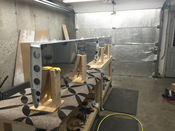
Today I was able to spend a bunch of time starting the final assembly and made good progress.
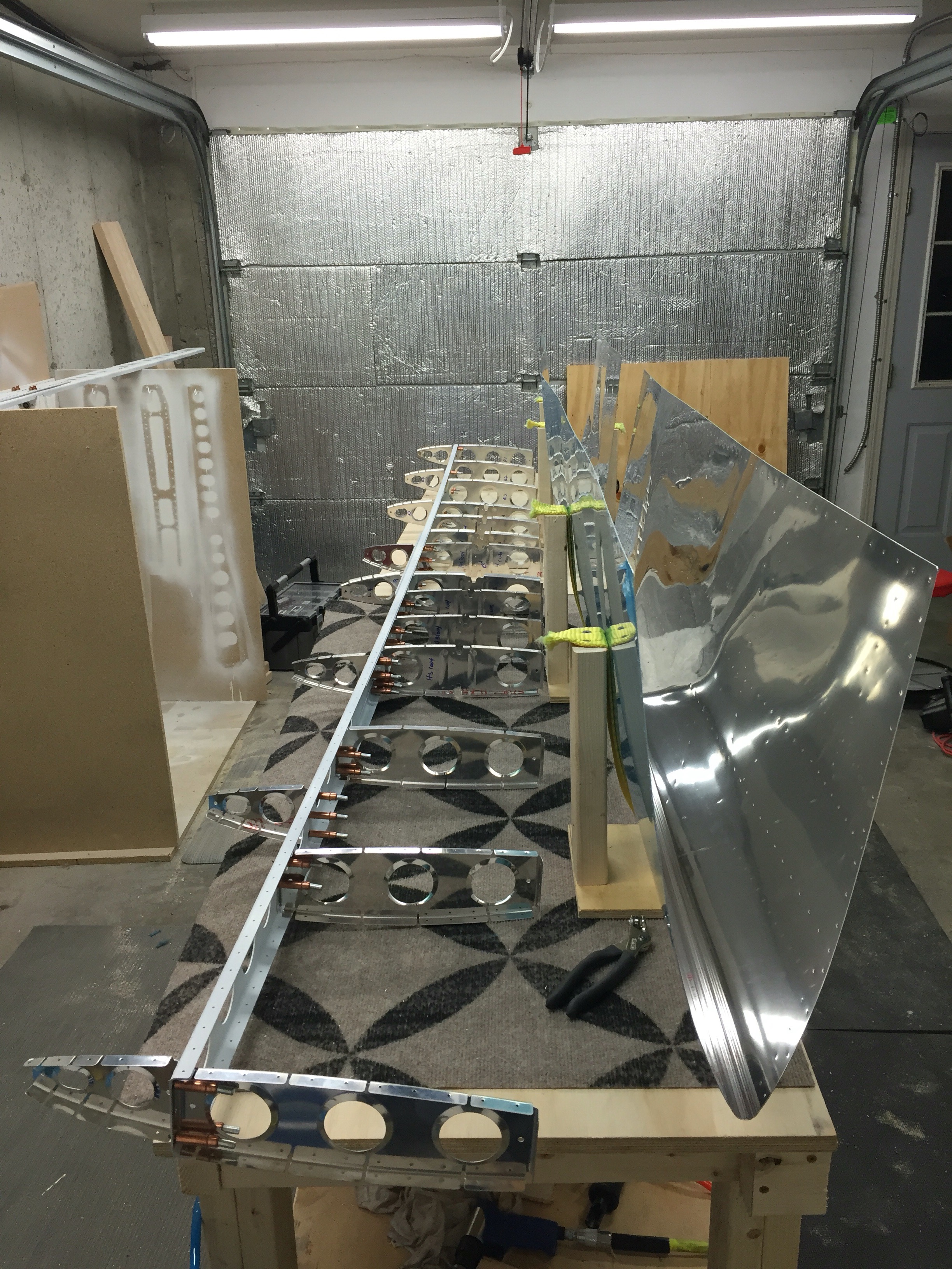
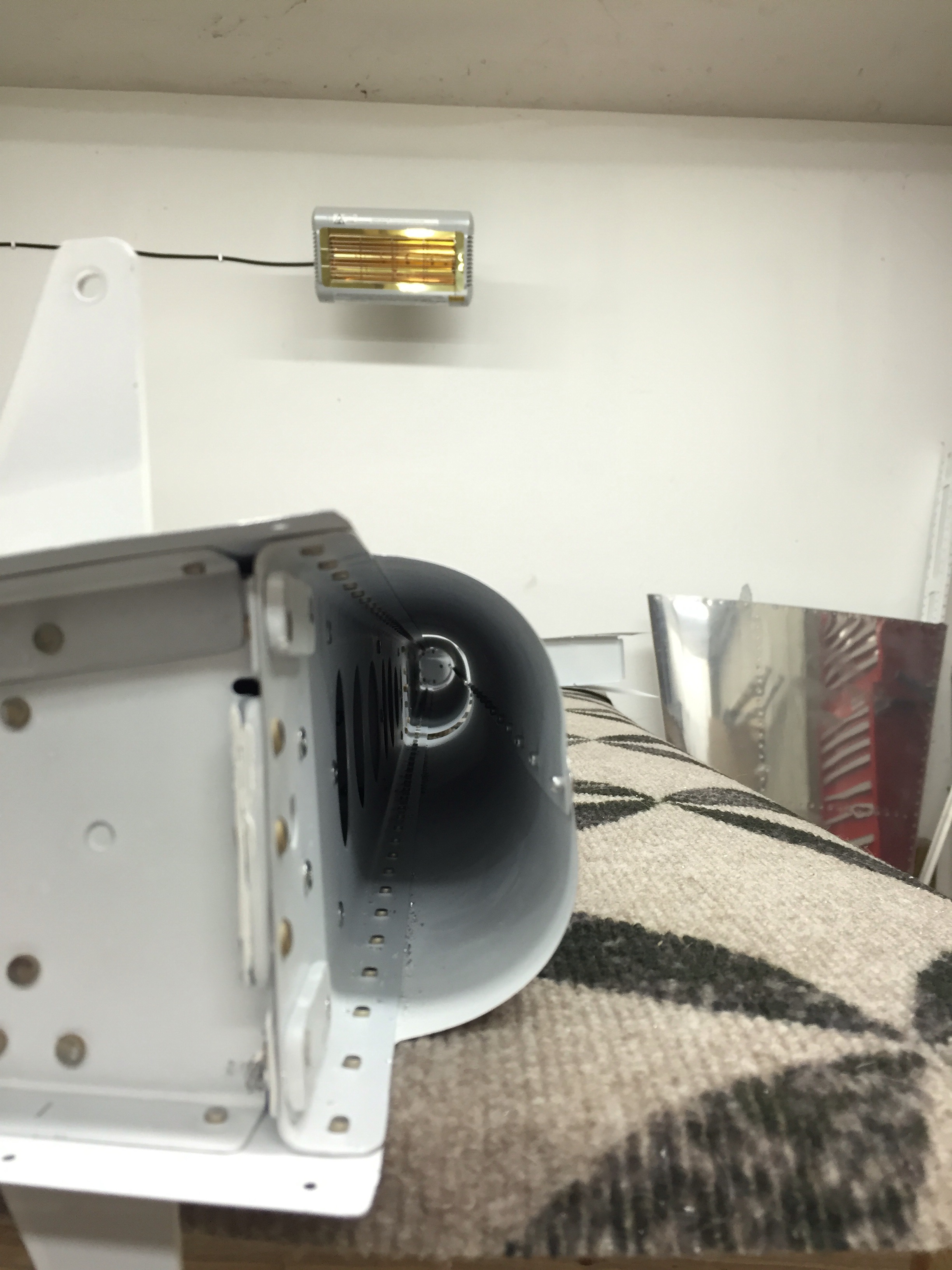
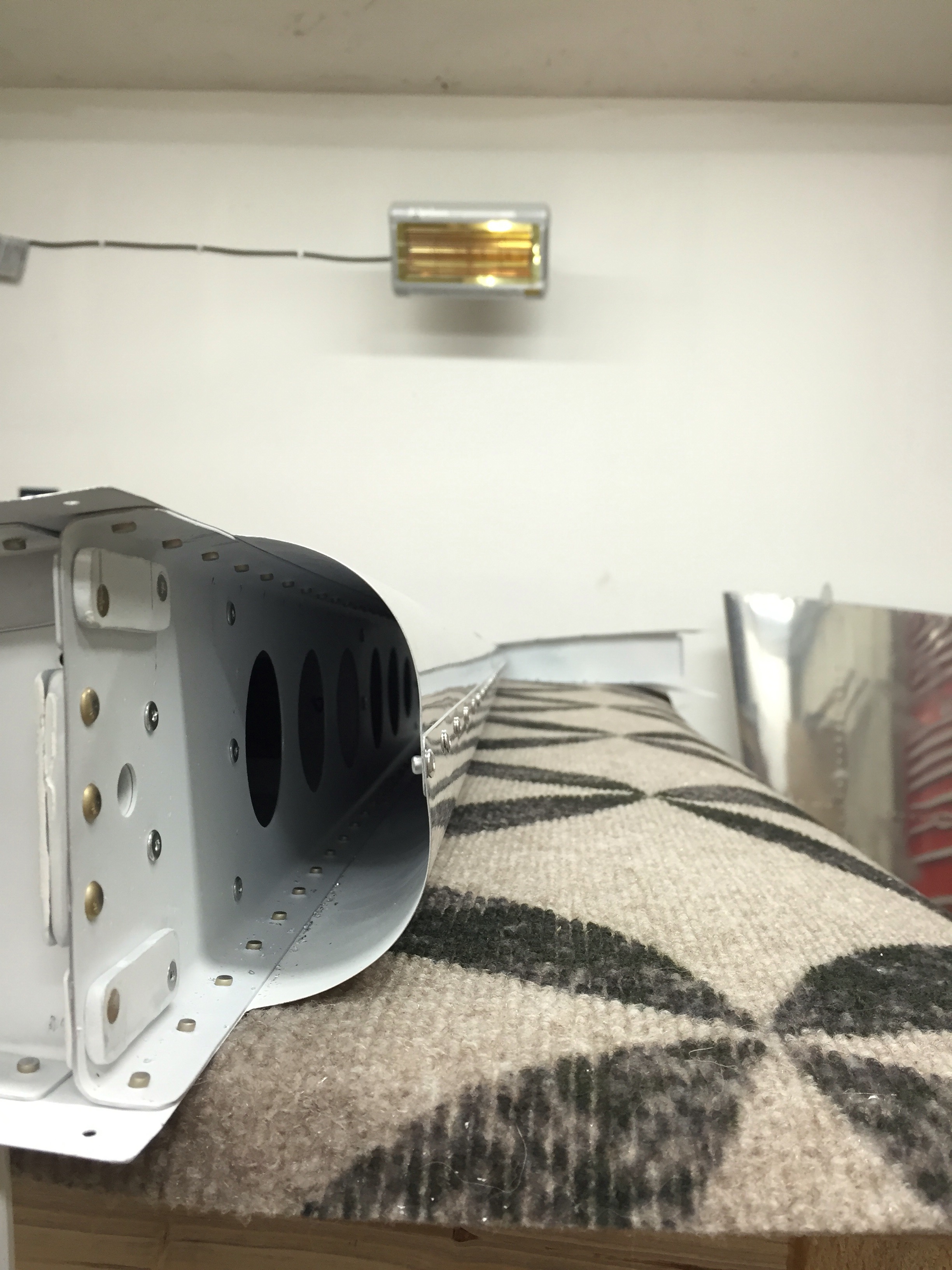
I was able to rivet together the stringers and stringer web, the basic skeleton to the front spar, the nose ribs to the skins, the front spar to the nose ribs, and started riveting the skins to the front spar. A couple of pictures of today’s progress.

Riveting the In-Spar Ribs to the Stringer Web

Stringers riveted together to the previous picture and Cleko’ed to the front spar

Most of the Skeleton cleko’ed in place

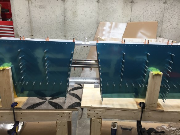
Looking down inside one of the “bays”. Skin is riveted to the spar here.

Nose ribs riveted in place as well as the left side skin to the front spar.
Since the last update I’ve been able to final drill all horizontal stabilizer holes common to the skins and the ribs/spars. Disassemble the whole thing, and deburr all the holes. Then dimple all the holes and machine countersink the spars and stringers. I really need a 3-4 hour window to prep, let dry, and spray primer; so I’ll wait until the weekend for that.
Some pics of the HS progress.


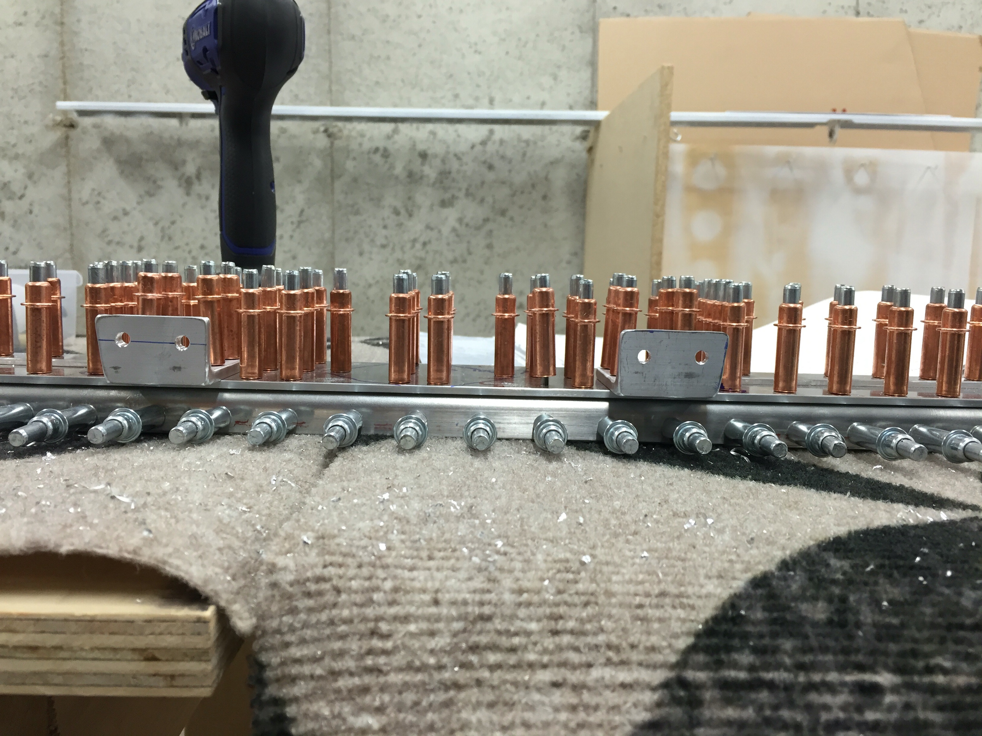
Not many silver clekos left – this part takes a lot!

Pile of HS parts waiting to be primed
So while I wait for a weekend day to prep and prime these parts, I decided to start on Section 9, the Elevators.
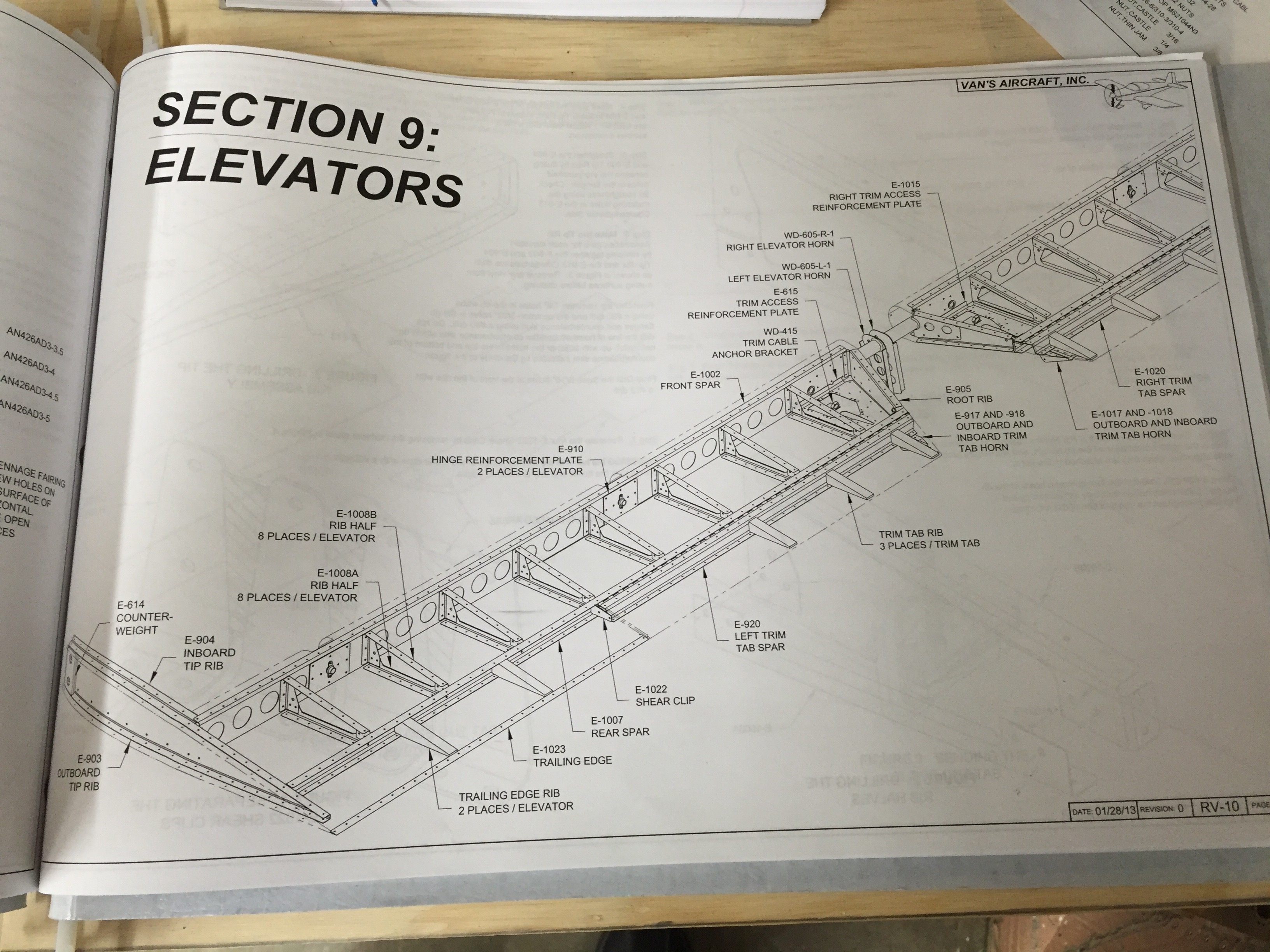

E-1008 parts separated and partially deburred.
Spring and Summer start filling up the schedule and life starts getting in the way a little bit.
I’m doing a crazy bicycle ride on June 11th that is 134 miles long and 8000′ of climbing. I’ve been spending as much time as I can training for that, which has taken up several hours each weekend. Also last weekend we had lots of people over the house to celebrate Greek Easter. So between that, and my drain plug in my compressor failing, yet again… I didn’t get much done the last couple of weekends. Additionally, we’ll be away 2 weekends in May.
My compressor is only about 2 years old, and the original drain plug bolt snapped in half right at the hole that’s drilled through it.
Last weekend after draining the tank and starting it back up again, air was leaking out of the drain still. After investigating and unintentionally unscrewing the bolt all the way out of the drain plug (that’s not supposed to happen) and having the bolt shoot out of the drain in a big burst of air… I found that there is no o-ring present anymore which is letting air leak by. So I went out and bought a brass elbow, extension rod, and a ball valve shutoff to make draining the tank easier to get to, and a more reliable mechanism.
I debated putting an automatic drain i, but I’m also having thoughts of upgrading to a 60 gallon 2-stage compressor too. So that will wait.

2nd busted drain plug 😦
I’ve spent what time I’ve had working on getting the nose ribs and inspar ribs all match drilled to the front spar and fabricating cradles to hold the assembly for final drilling and riveting. I decided to try straps for the cradles instead of making them rigid after seeing what Jason Ellis did. The cradle doesn’t influence the shape at all, it’s simply a method to hold things up while working on the HS. The straps also allow a little bit of movement, if needed.
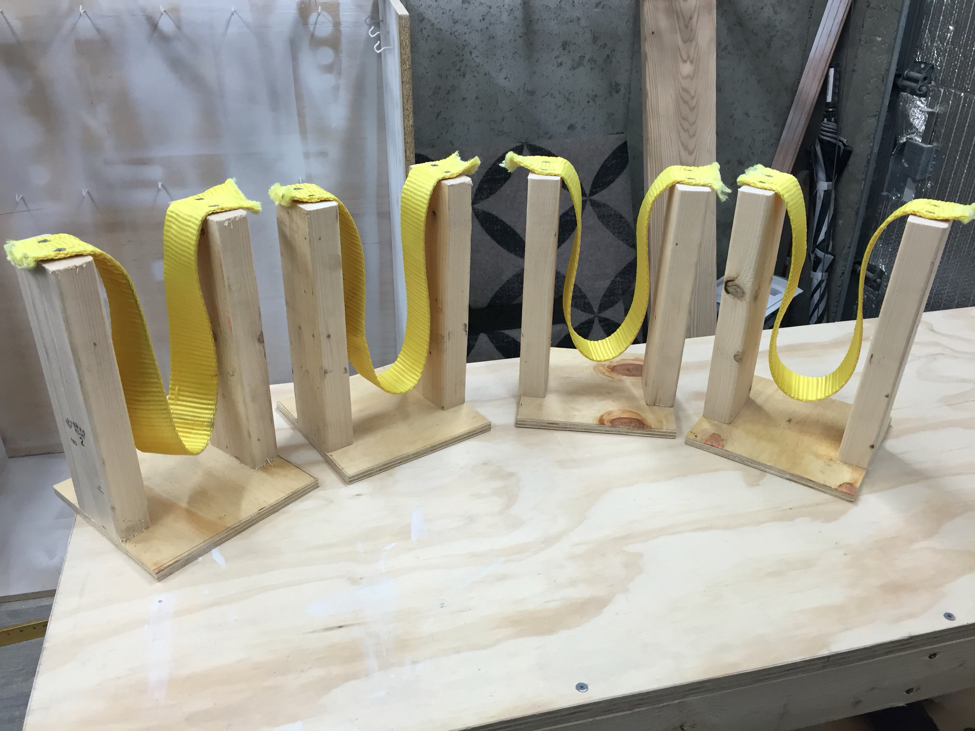
Wooden Cradles
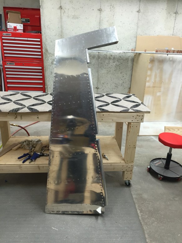
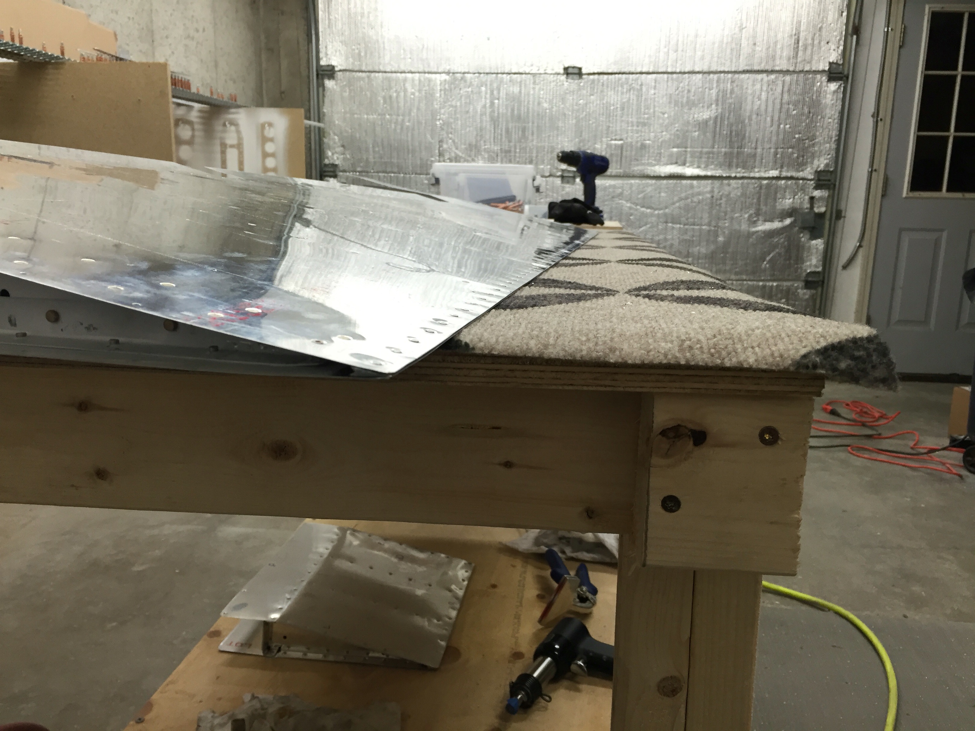
A picture of the Horizontal Stabilizer skeleton, with all the nose ribs and in-spar ribs attached.
X

Skins sitting in the cradles
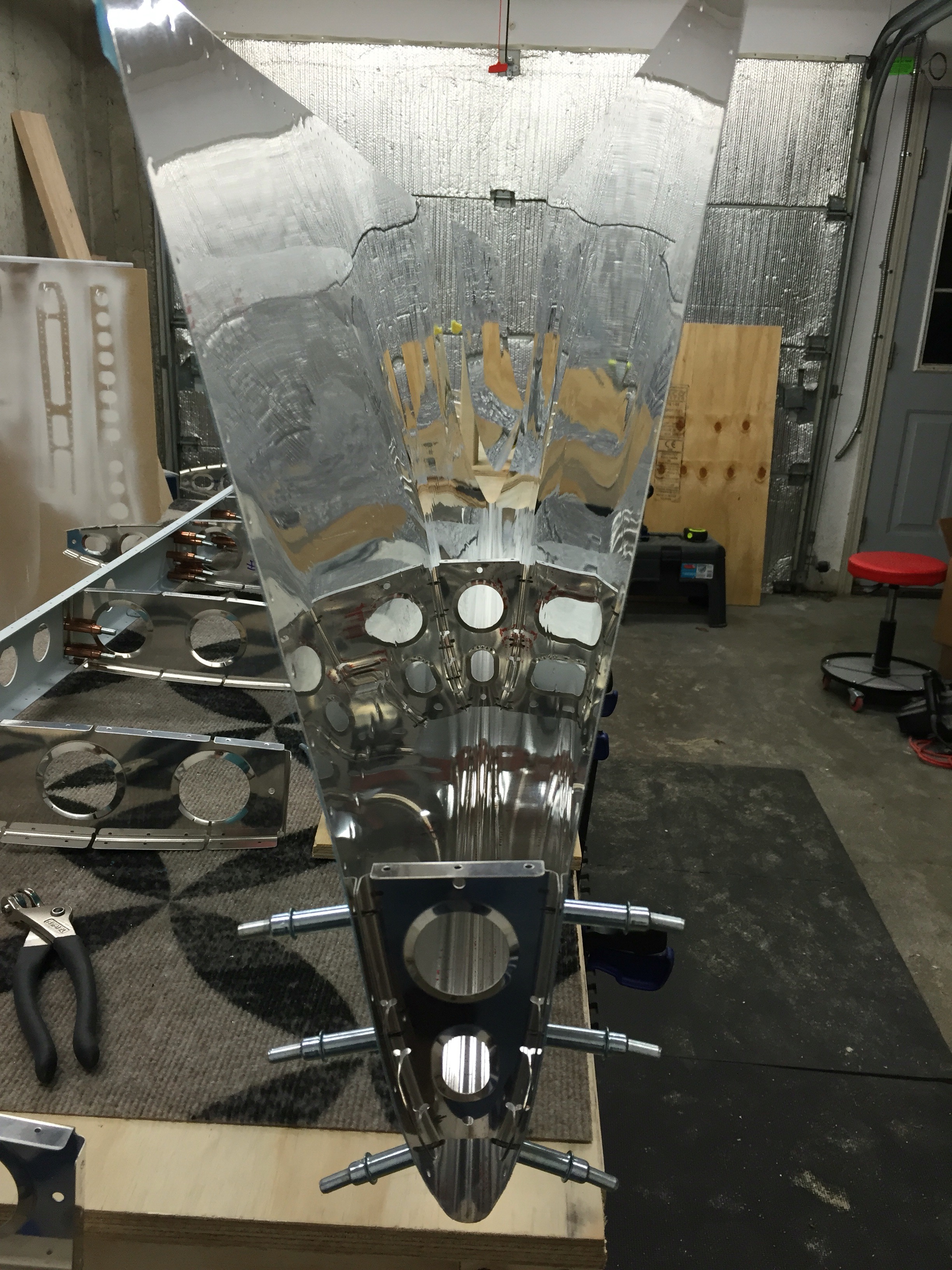
Starting to Cleko the nose ribs to the skins.
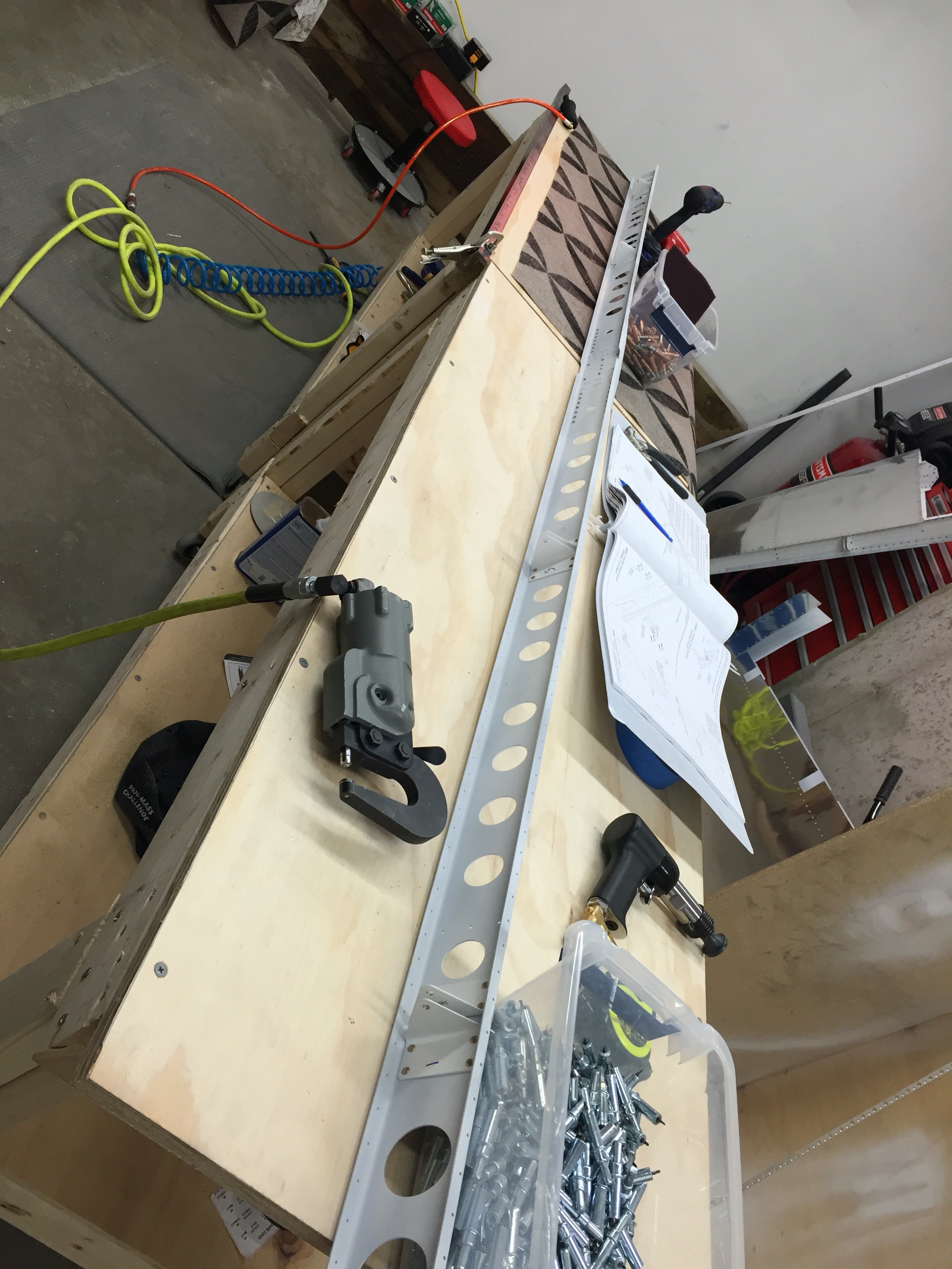
Mostly just posting some pictures from some Horizontal Stabilizer progress. I’ve finished initial riveting of the front spar, doubler plate, and attach brackets.

Aligning the attach brackets with something straight (steel bar)

Attach Brackets Match drilled

Primed. Doubler and Attach Brackets Riveted onto Front Spar

Backside View of the above Photo
I’m now working on the tedious task of deburring the in-spar ribs and nose ribs. I really hate deburring ribs. There are so many nooks and crannies to deburr. I suppose though that if I had to make that part from scratch, that it would take a lot longer than the deburring I’m doing.
Also, while riveting the front spar, I managed to trip over my air line and pull my squeezer off of the bench onto the floor. The result was the trigger pin jammed in the on position…
 I emailed Isham, my tool vendor, and he got back to me almost immediately. It ended up being a simple fix. I removed the air swivel input, spring, and pushed the trigger pin out. Ran a reamer though the hole to get rid of any oblonging, and oiled the trigger pin back up and re-assembled. Seemed to fix the issue, and was able to use the squeezer to finish up the spar.
The last 2 nights I spent rolling and riveting the leading edges, installing the counterbalance weight, and finishing the last few rivets on the front of the skins.
The rolling of the leading edges was made pretty easy with the tool that I mentioned in my last post.


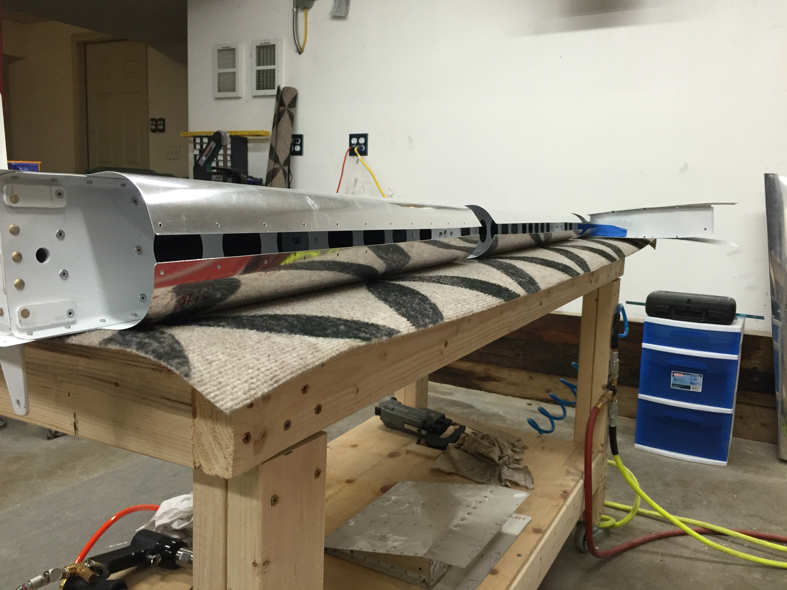


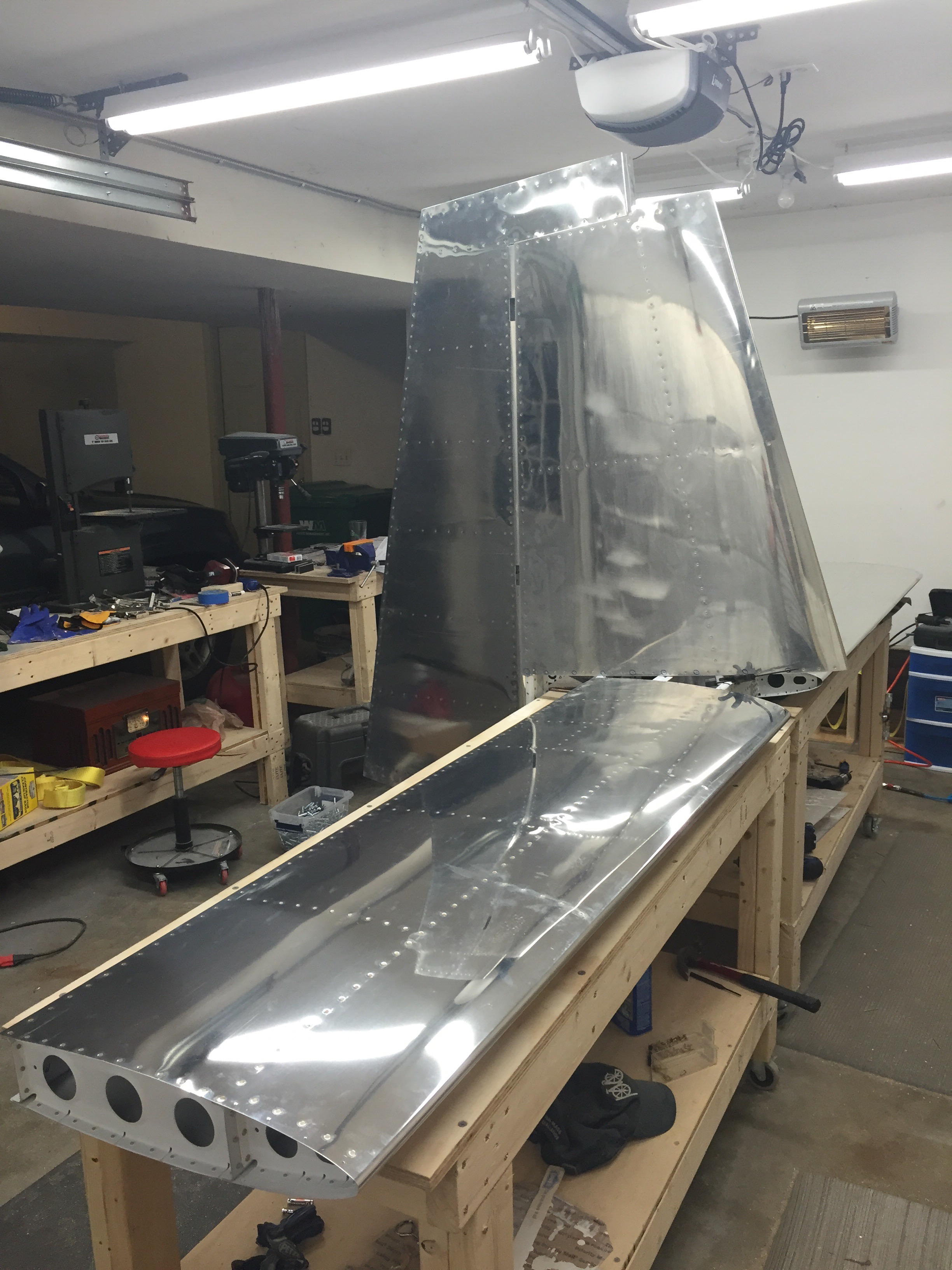
Didn’t take any pictures of the counterbalance weight, but some obligatory pictures of the rudder and the rudder/vertical stabilizer combo.


I spent some time today getting the top rib riveted along with the skins to the main spar. The counterbalance rib was riveted on next. Then it was time to move onto the trailing edge of the rudder and riveting a “double flush” rivet. Essentially a normal flush rivet where the shop head is set in a dimple and set flush to the skin on both sides.
I ended up using my pneumatic squeezer to partially set each of the rivets along the trailing edge. Starting in the center and working towards the outside edges, I partially set every 10th rivet, then every 5th rivet. This kept on until all rivets were partially set. I then used a flush die set in a C-frame rivet set holder in my rivet gun to finish each shop head flush to the skin following the same pattern that was used to partially set them. All the while making sure that there was no bowing, hooking, or pillowing of the edge going on. An overview of the technique below:

I’m not 100% happy with how it turned out, but that’s just the perfectionist in me. The results were a relatively straight trailing edge.


Shop Heads Flushed to the skin in their dimples
Next up is rolling the leading edges. The idea here is to tape the metal to a rod and roll it upwards creating a nice even bend in the metal.

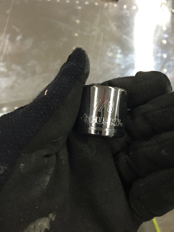
I recently read on Van’s Air Force a tool that Eric, a fellow RV-10 builder, had created to make this job easy. I decided to give it a try, so in preparation to do that, I spent some time fabricating this tool from some closet rod, two 3/8″ drive sockets, and JB Weld that I bought from Home Depot.
I had purchased 1.25″ diameter closet rod, as that is the size suggested in the RV-10 plans, and 7/8″ sockets, which fit perfectly inside. I cut the rod to match the length of each leading edge section to roll. I also drilled some holes in the closet rod end and also used the grinding wheel to scruff up the sockets for better adhesion of the sockets to the rod.


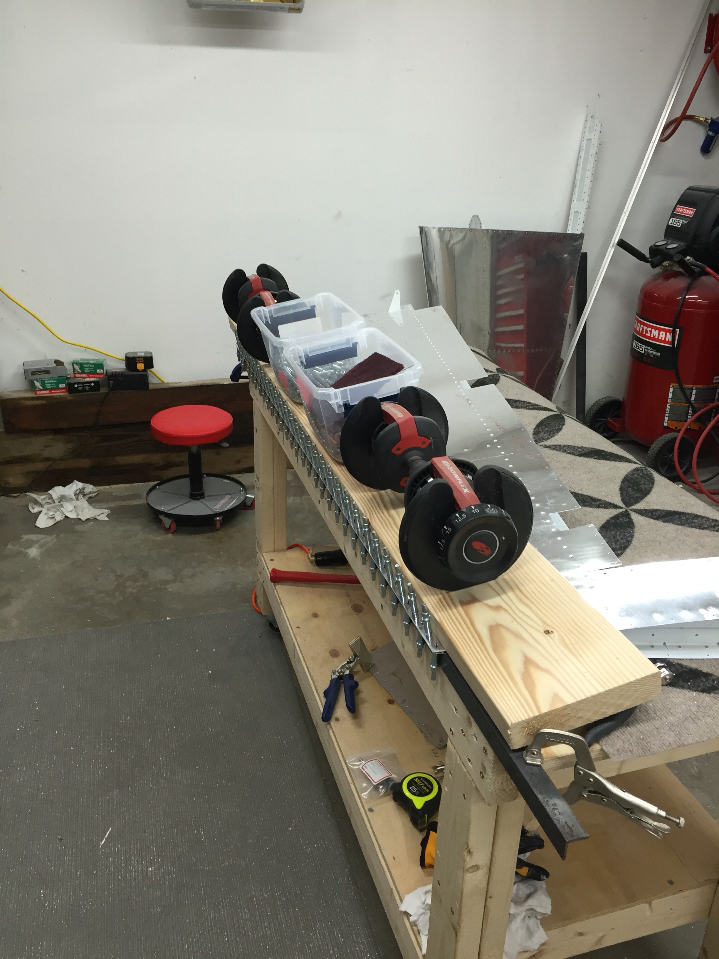
Once this dries overnight, the idea is to use two 3/8″ drive socket wrenches in each end to easily roll the metal taped to the rod.
The 3M VHB tape from Van’s showed up this week, so I was ready to start back on the rudder again. Thankfully, this time the tape VAN’s sent worked like a charm. This further validated that the tape I got from Amazon was junk. The night that the tape came in, I adhered it to the trailing edge wedge piece. Tonight I attached the wedge to the right skin which sits flat on the table. Clekos were installed from the underside of the skin in the trailing edge at the end of each stiffener. I then got my wife to help me as we rolled the left skin onto the right skin, stopping at each stiffener location to finish the internal riveting of the stiffeners and shear clips, peeling back the 3M tape on the top of the wedge piece as we went. Once this was done, I finished riveting the lower rib to the skin, and installed clekos in the rest of the holes of the trailing edge in an alternating fashion. I clamped a 6′ steel angle to the edge of the table to give a straight and uniform edge. Finally, I put a wide board over the skin with some weights on it to hold it down and let the surfaces bond to each other. I’ll leave it overnight like this. Good progress tonight!

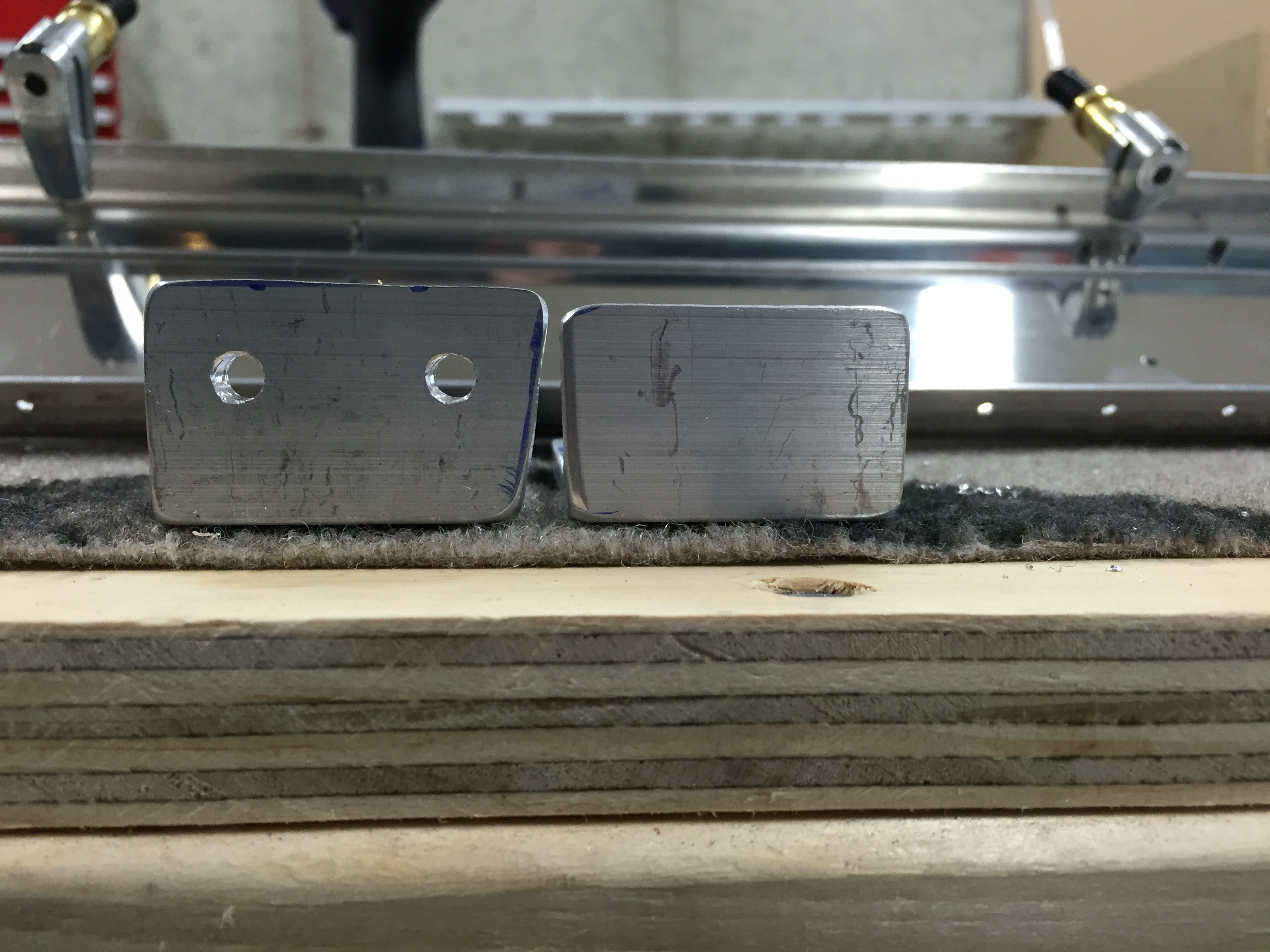
Was bound to happen sooner or later. Friday night I started fabricating the Spar attachment brackets from a piece of Aluminum Angle.
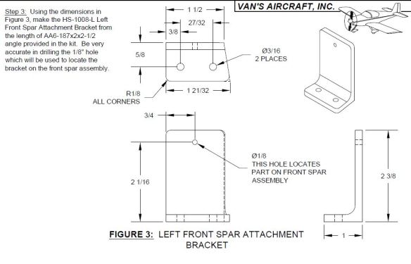
The first one (left one shown here) came out fine. It seemed to take about an hour to do one of these to be accurate. Today I started out making the right one, which is basically the same, but flipped in orientation. The first mistake was cutting the “mitered” edge which starts from a width of 1 21/32″ in the front to 1 1/2″ in the rear before I had cut the bottom leg down to 1″. I ended up with a final width only 2/32″ wider in the front compared to the rear…. Second mistake happened while cutting the other leg down to 2 3/8″. I didn’t get a straight cut, and ended up with a crooked edge. At that point, I decided to scrap that part and seeing I didn’t have enough angle left to make another attempt, I’ll need to order a new one. A 12″ long piece is $9, so not too terrible.
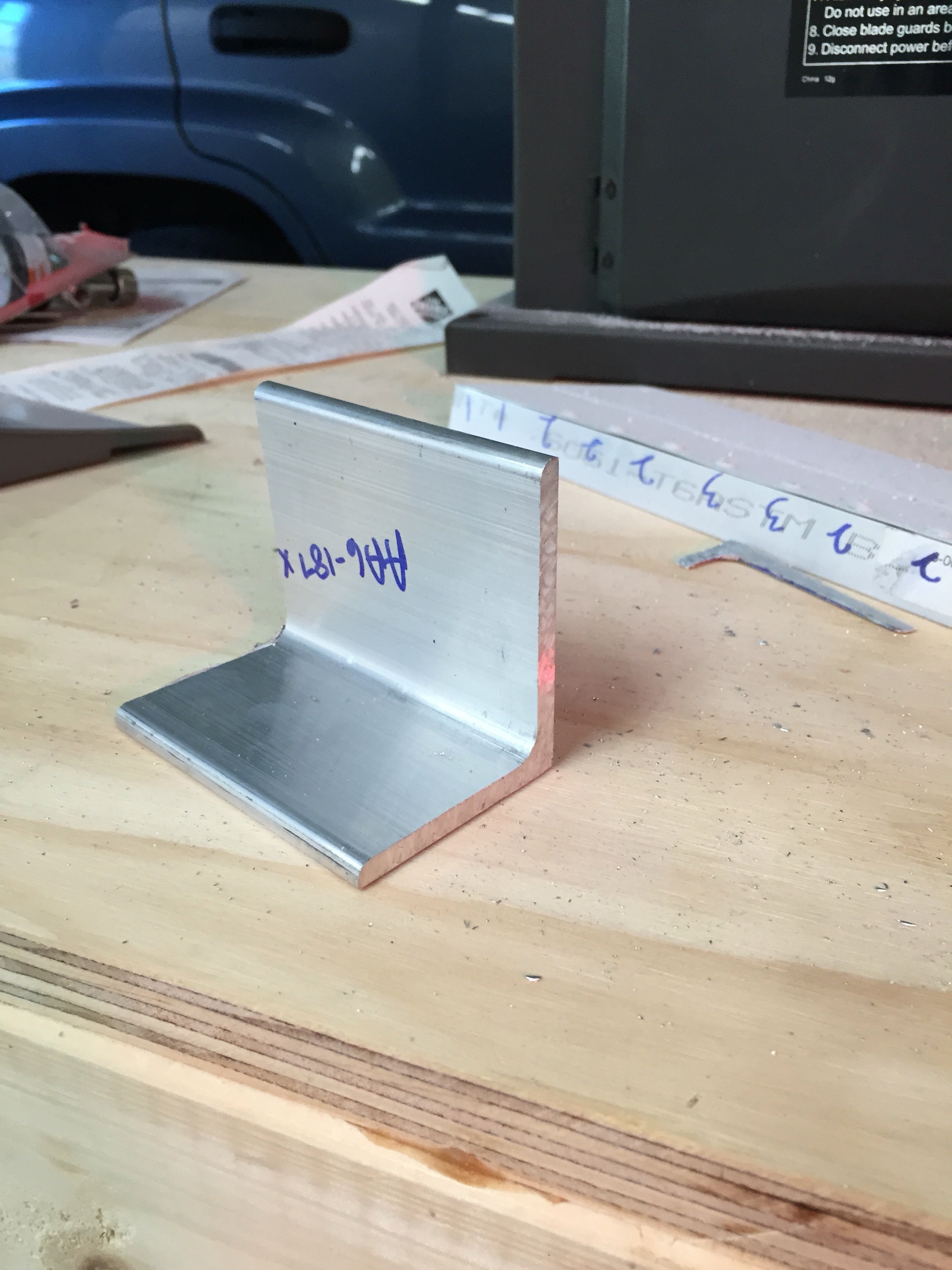
The stock aluminum angle to make these parts from:
 Here is the good one on the left and messed up one on the right

I was then able to get the forward spar and spar caps cut, deburred and drilled. I also deburred the spar doubler before calling it a day.


Also the VHB tape I got on return from Amazon did the same thing as last time. So I’ve returned those rolls and ordered some from Vans. Hoping that will work so I can finish up the rudder that is on hold at the moment.
So while I wait for my replacement roll of 3M VHB tape from Amazon, which actually came today, and at first look, seems to behave better than the first roll I got…. I riveted together the rear spar, stiffener, and hinge brackets of the Horizontal Stabilizer. I was also able to assemble and rivet together the inboard hinge bracket and bearing assembly. Some pictures of the progress…


