More HS

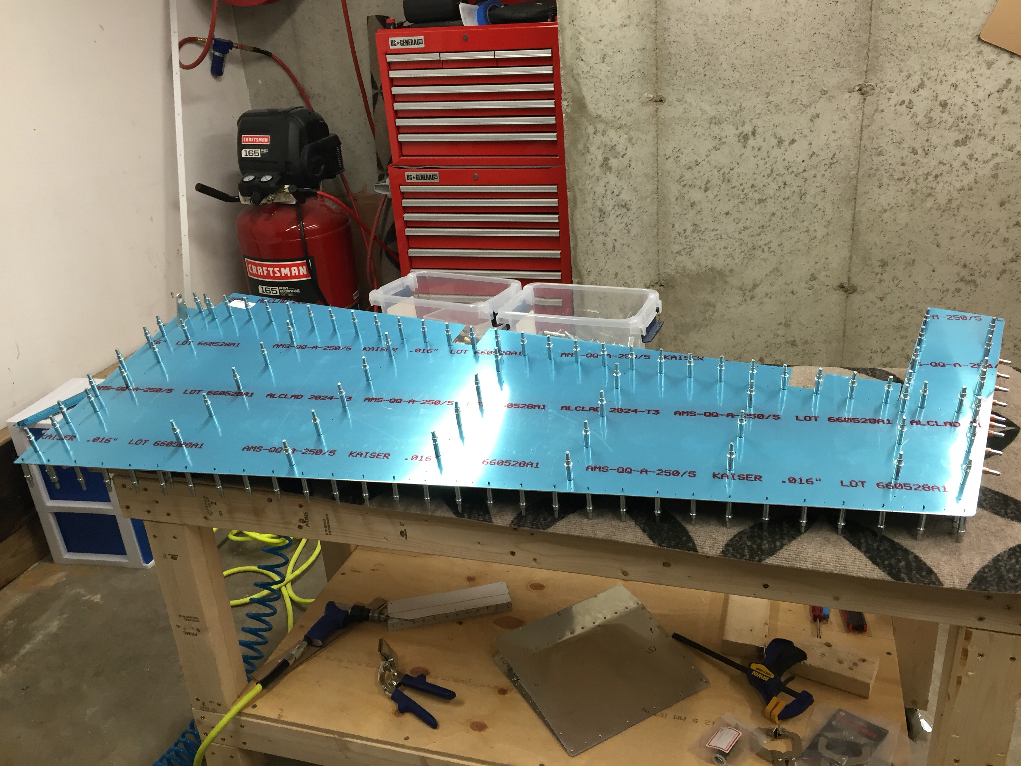
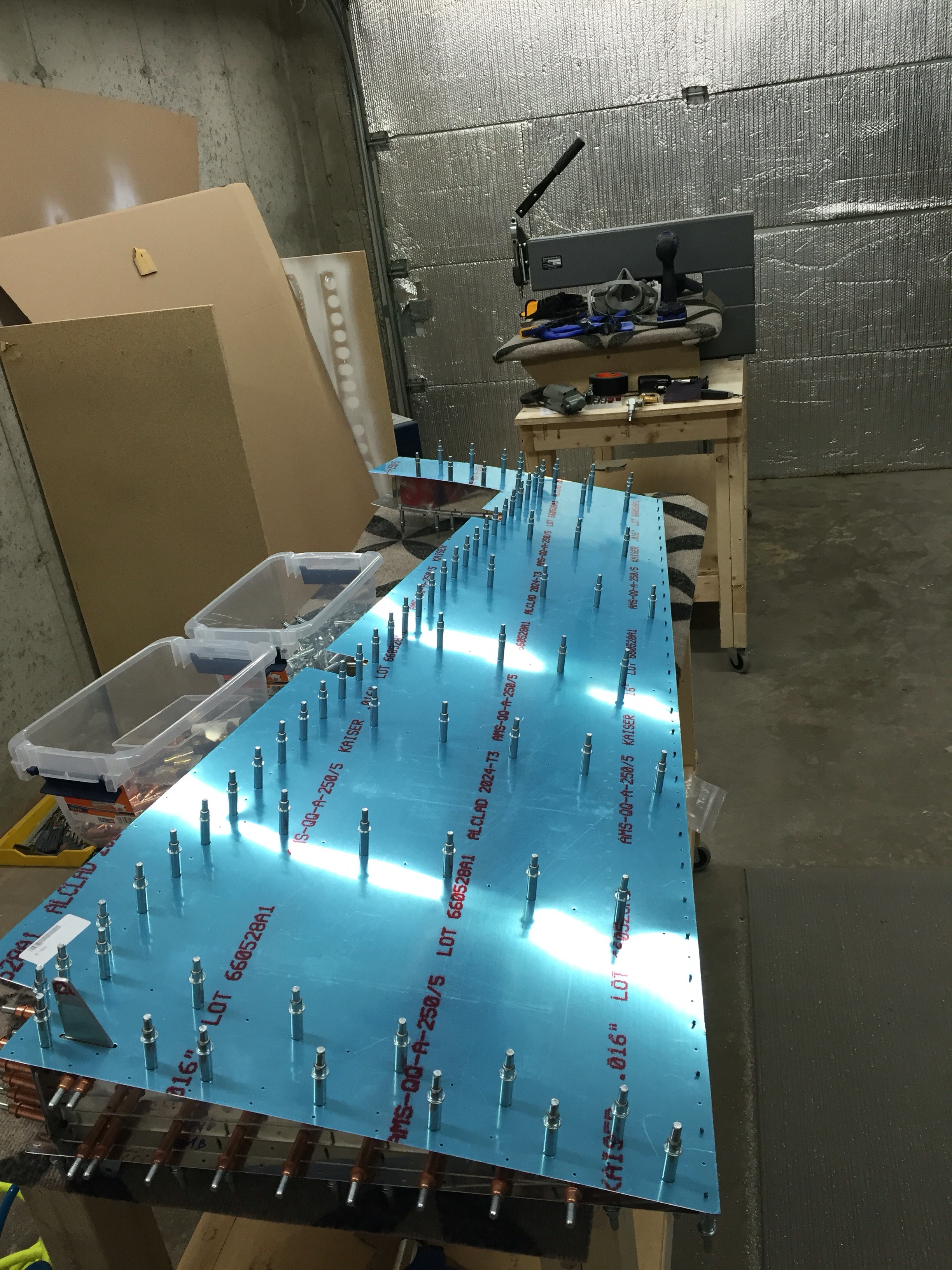
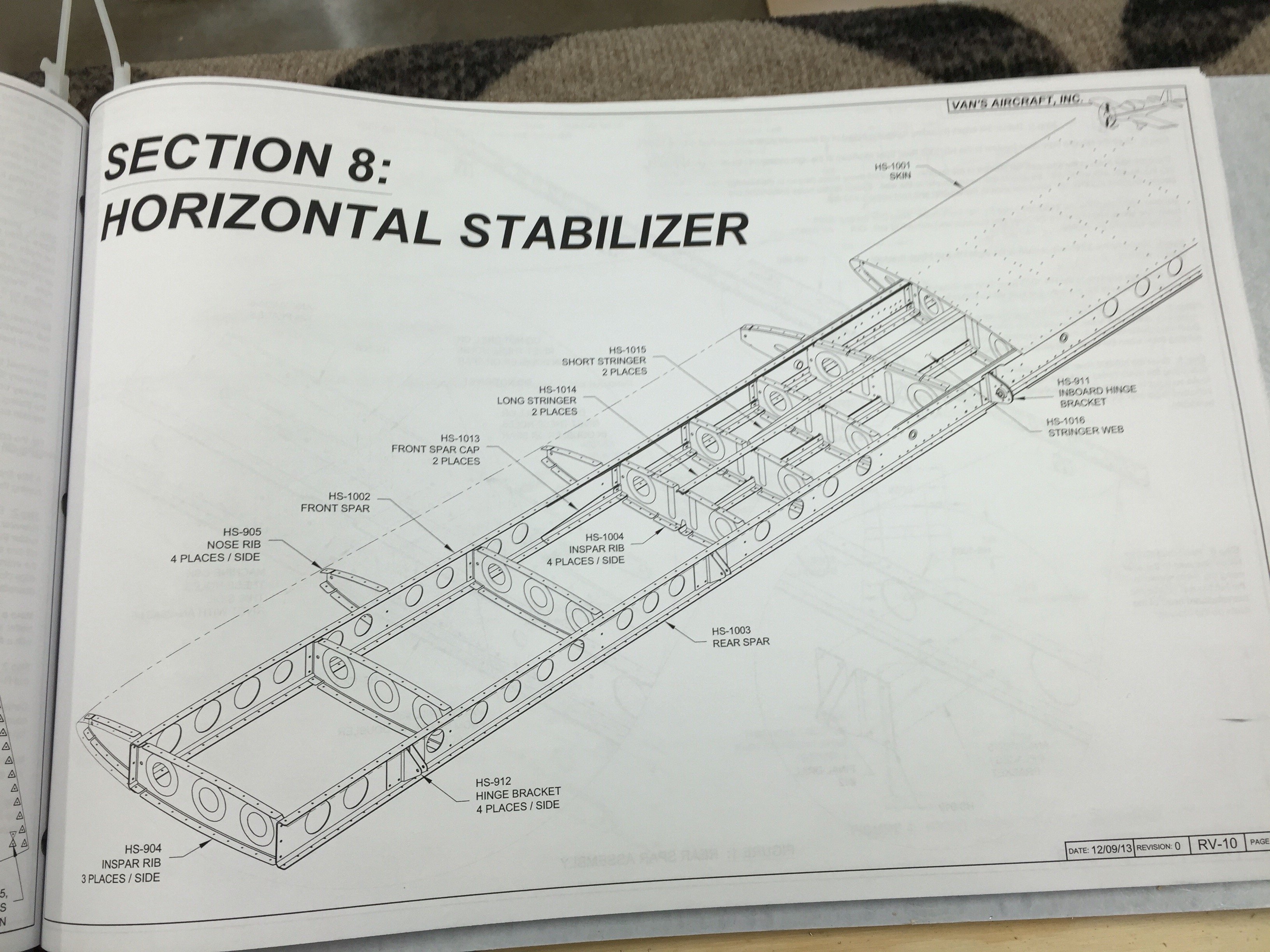
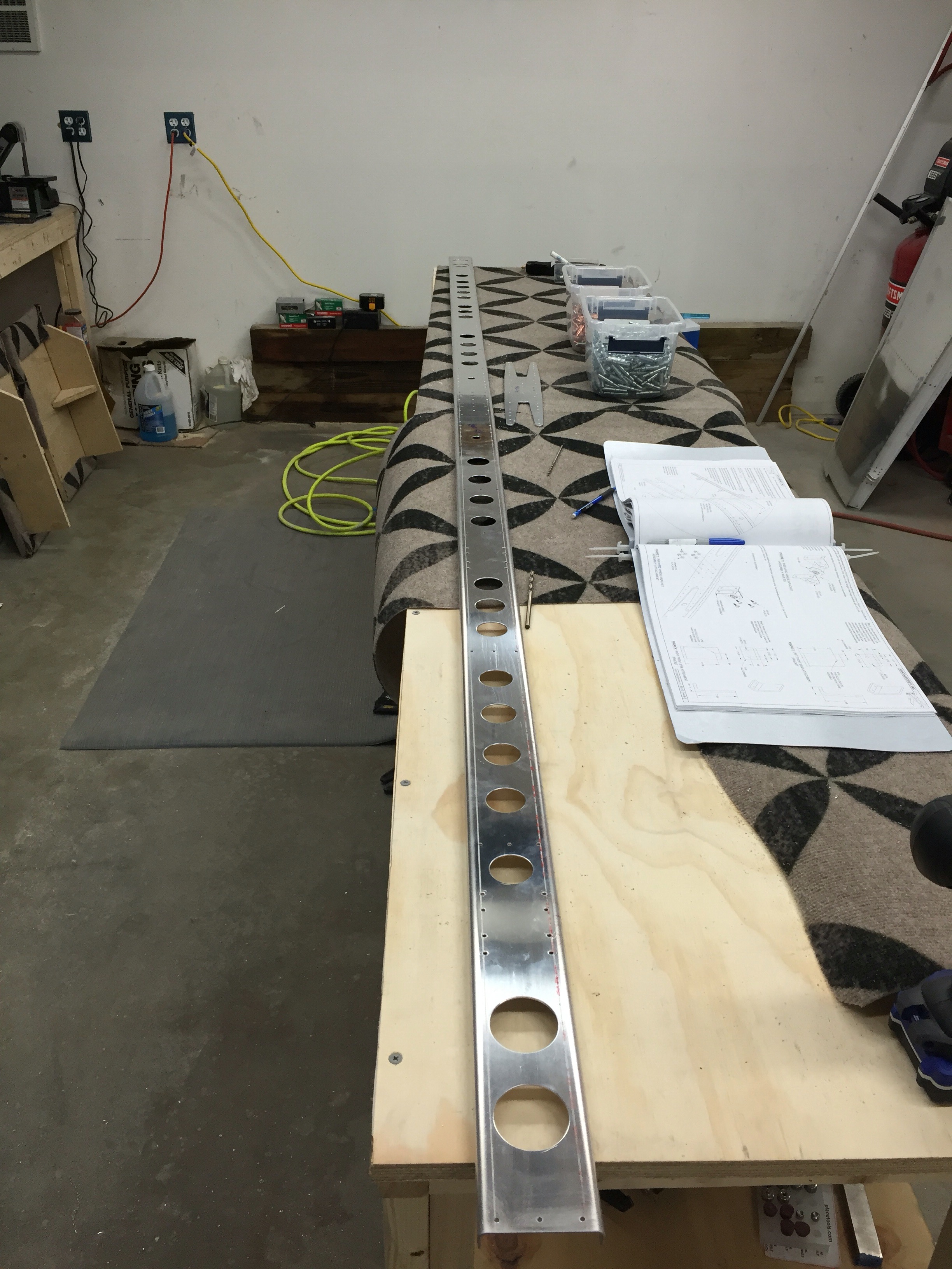
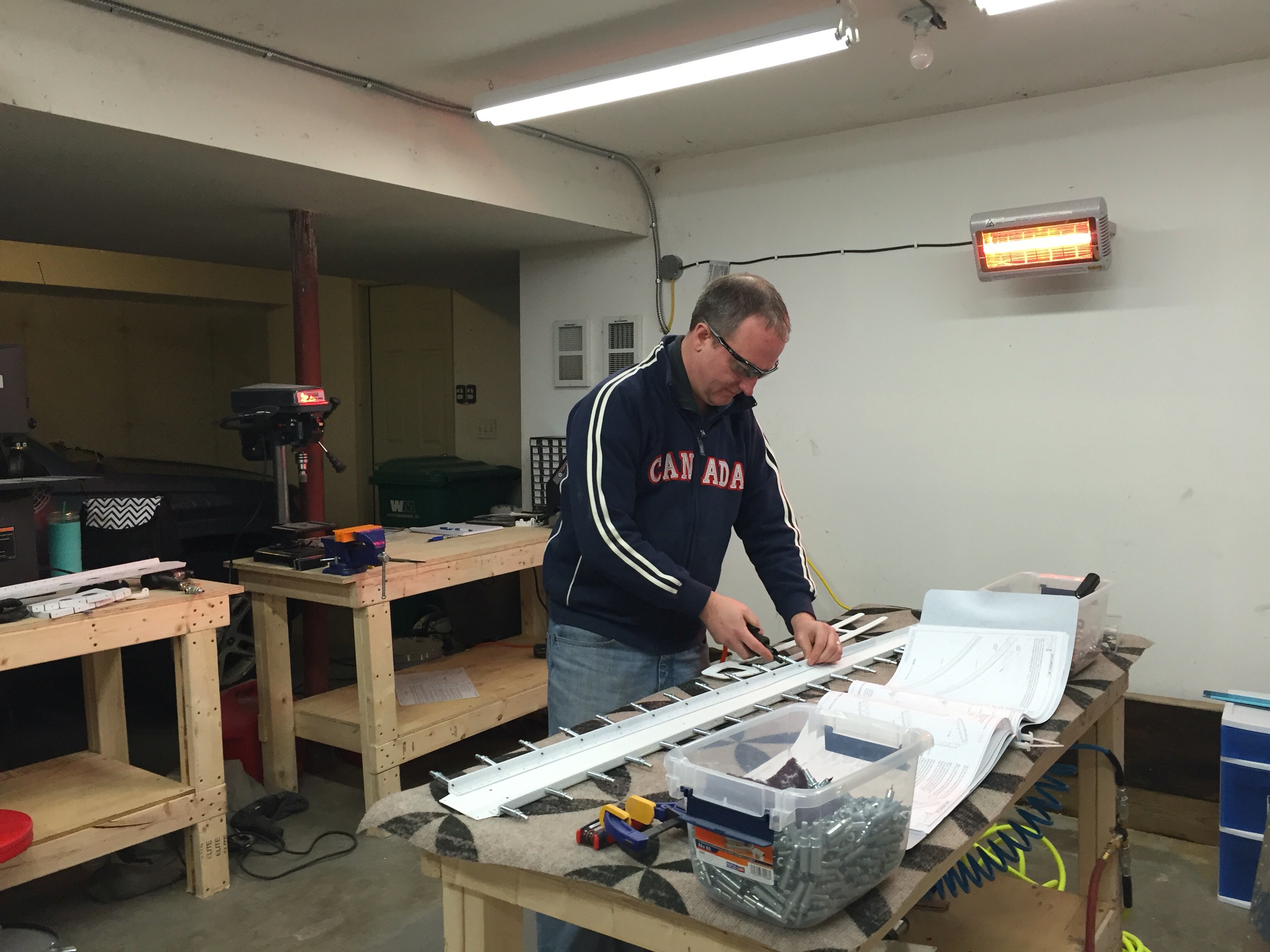
Mostly just posting some pictures from some Horizontal Stabilizer progress. I’ve finished initial riveting of the front spar, doubler plate, and attach brackets.


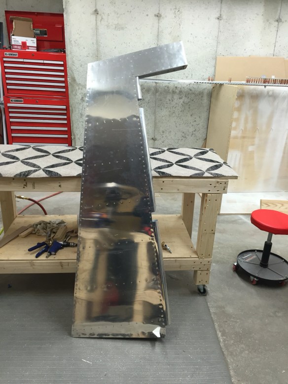
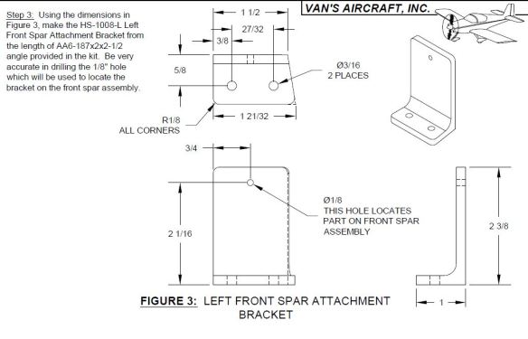
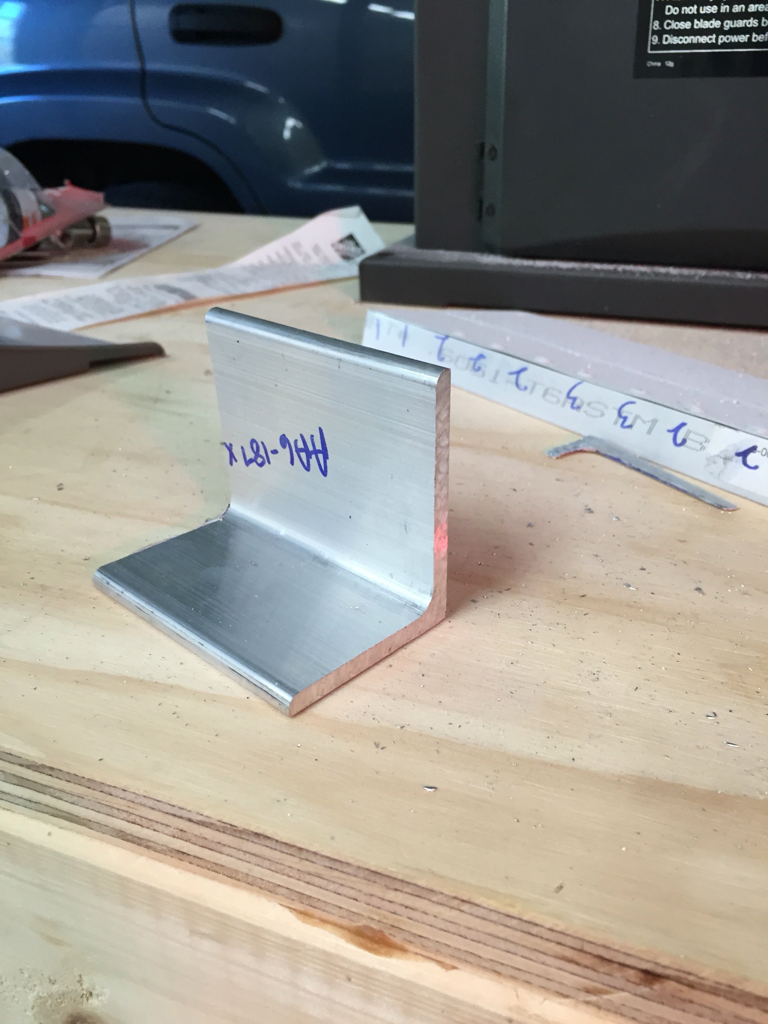
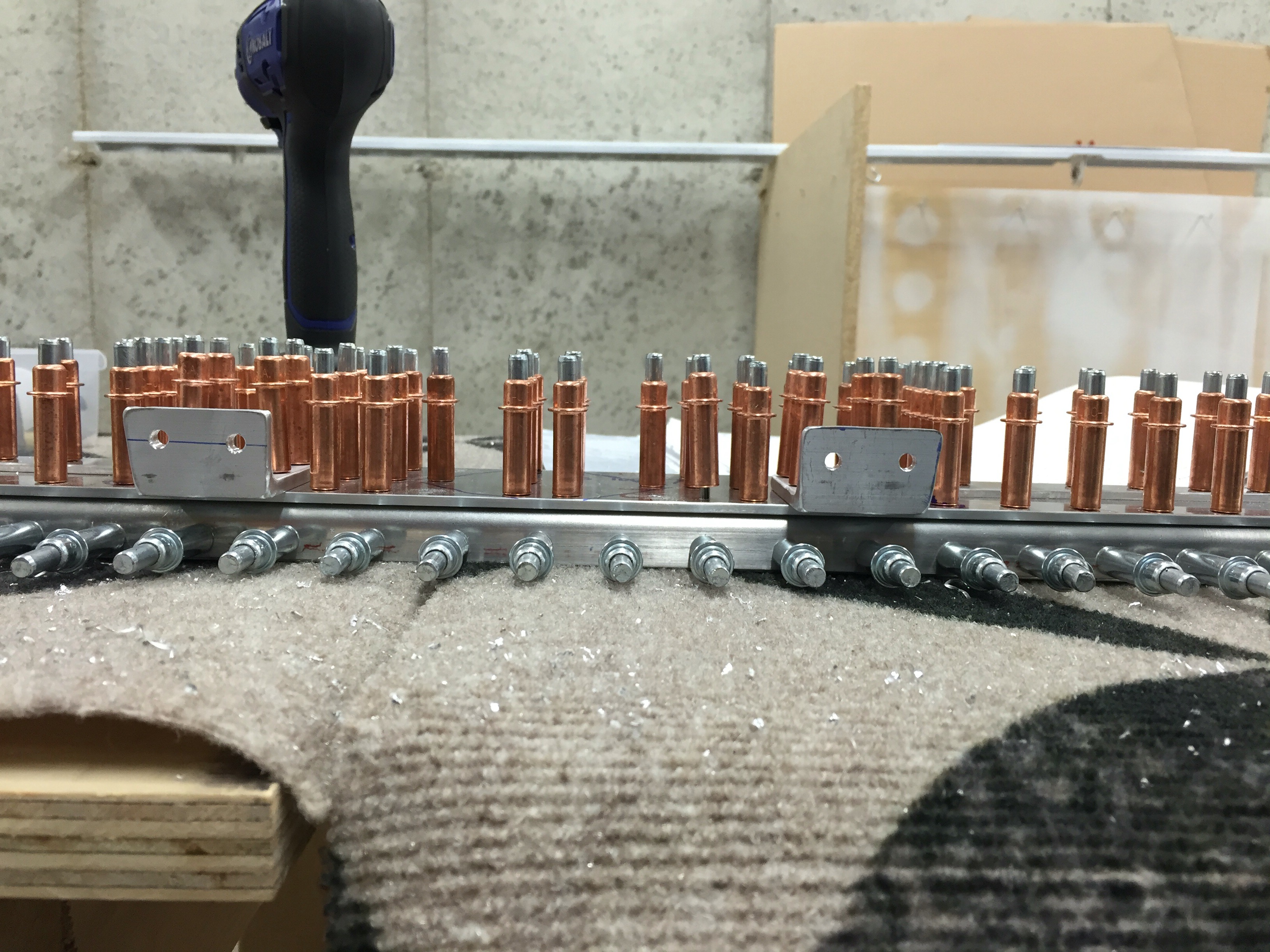
Aligning the attach brackets with something straight (steel bar)


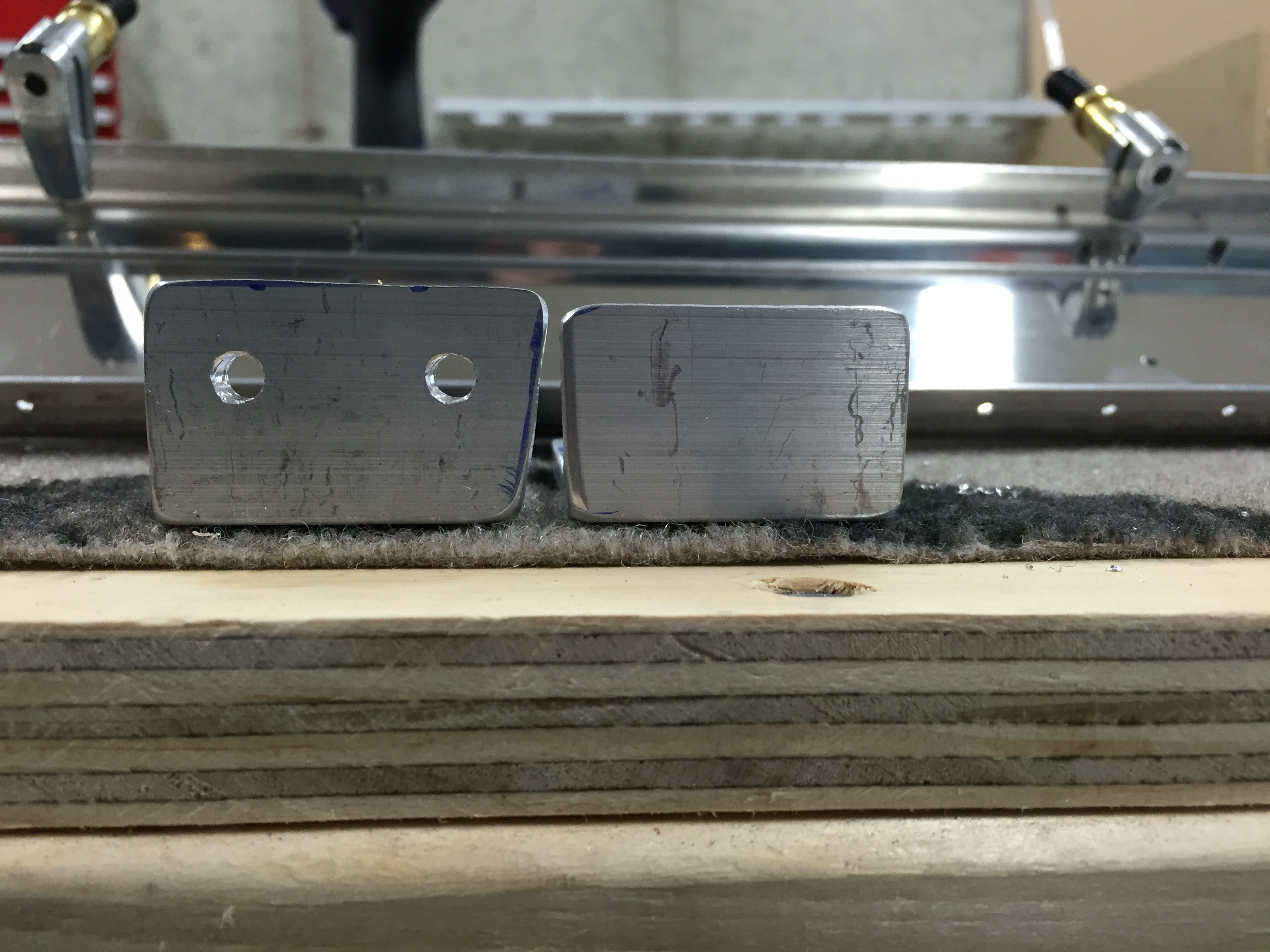
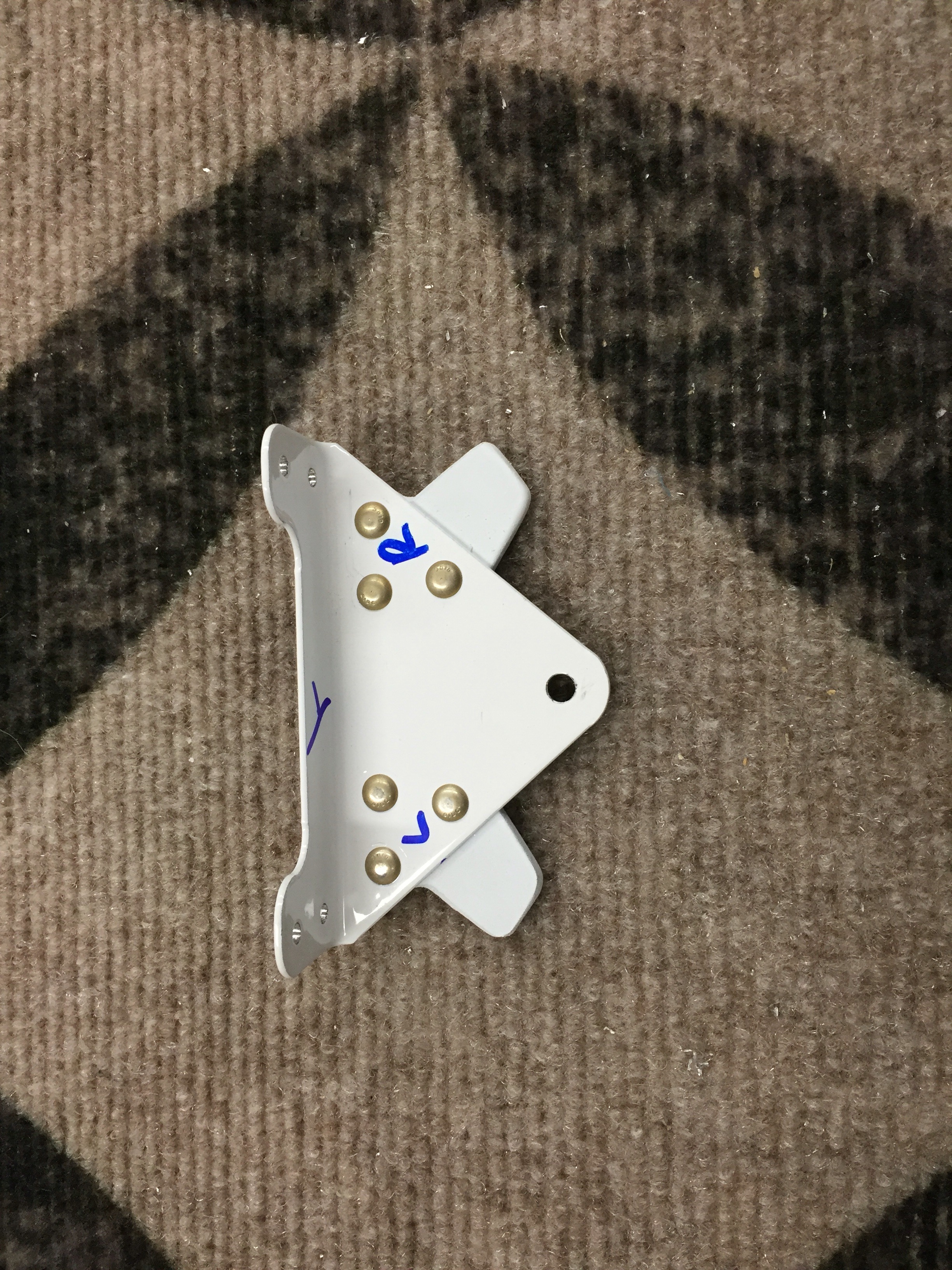
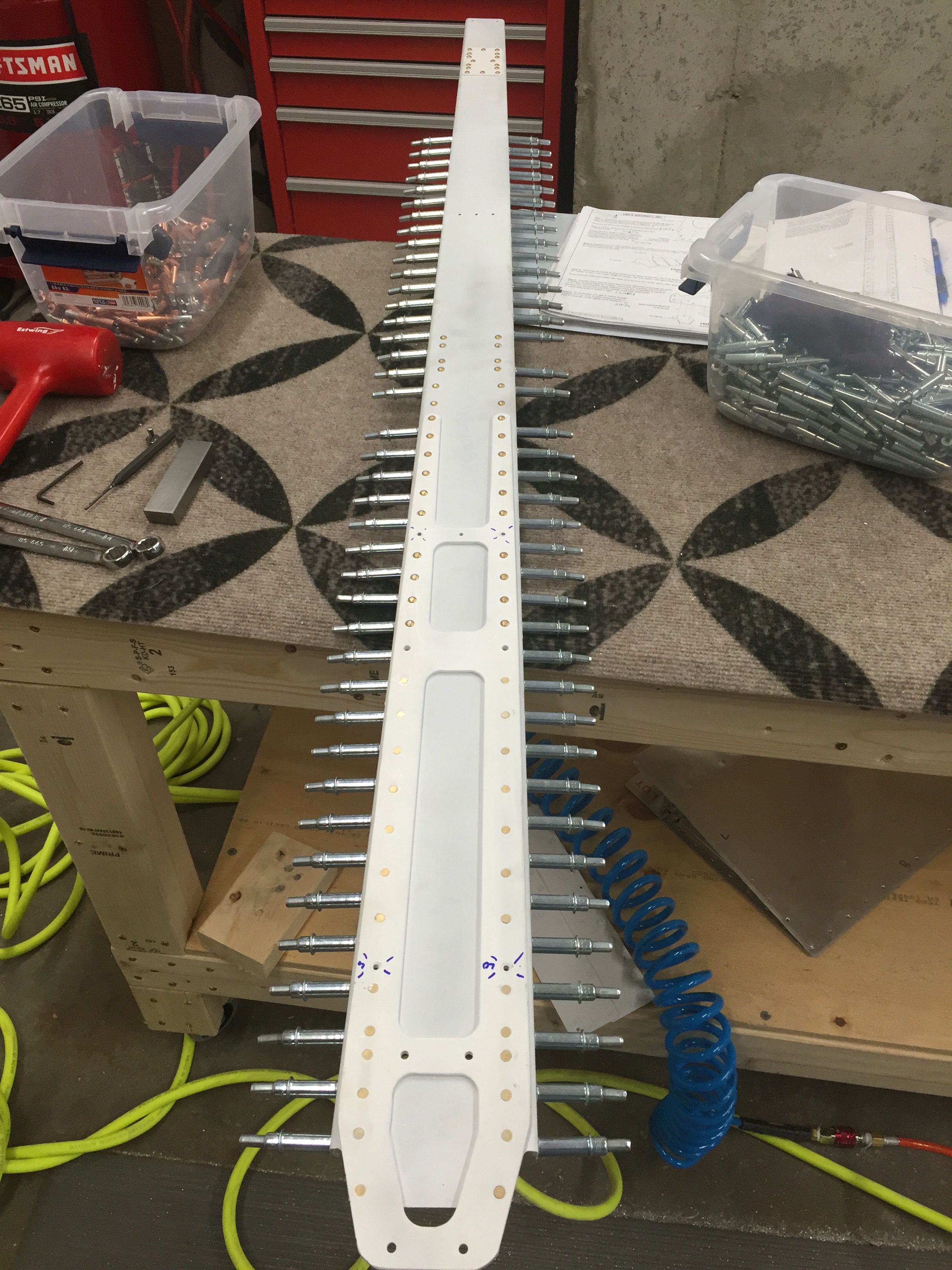
Attach Brackets Match drilled

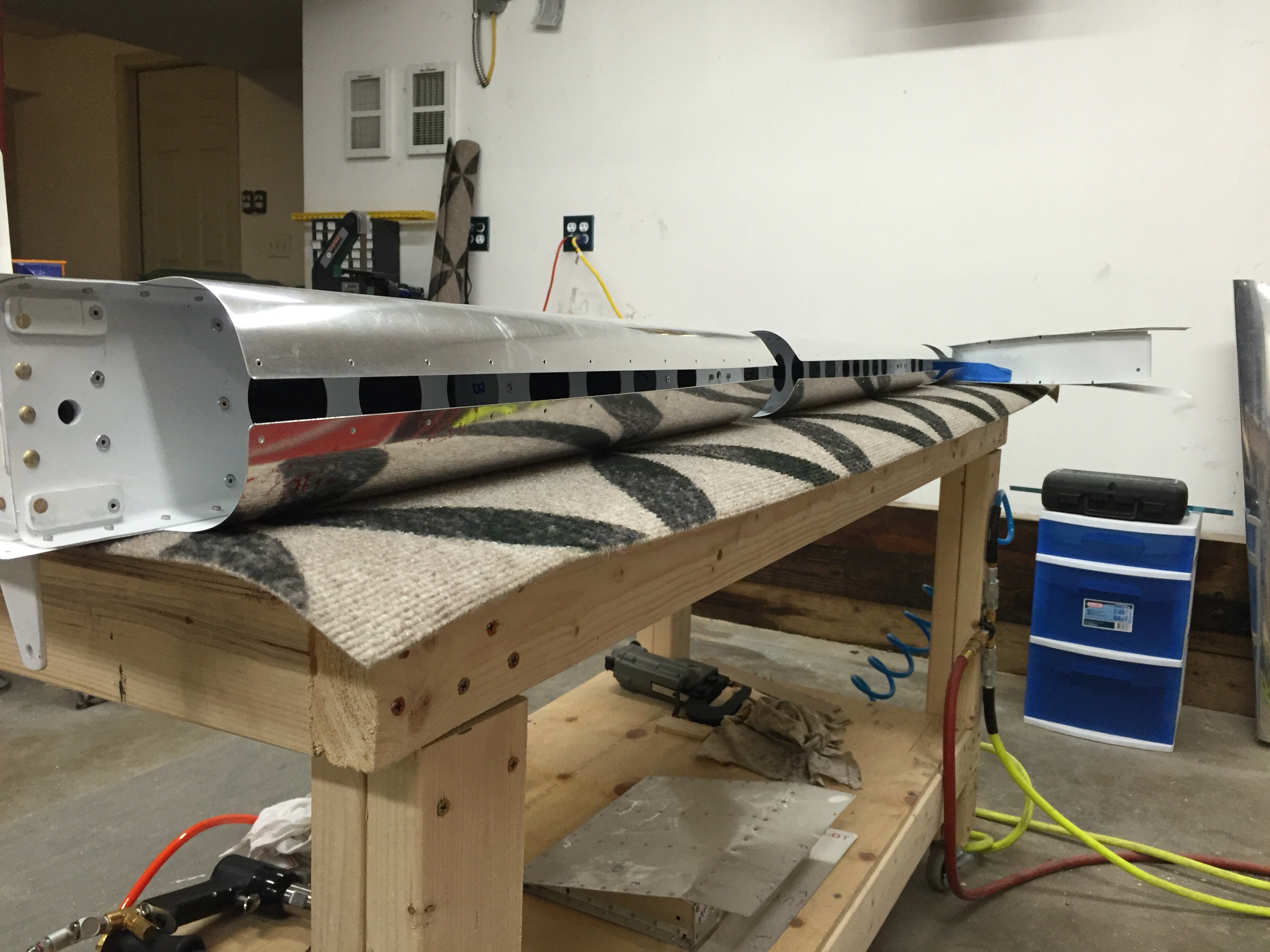
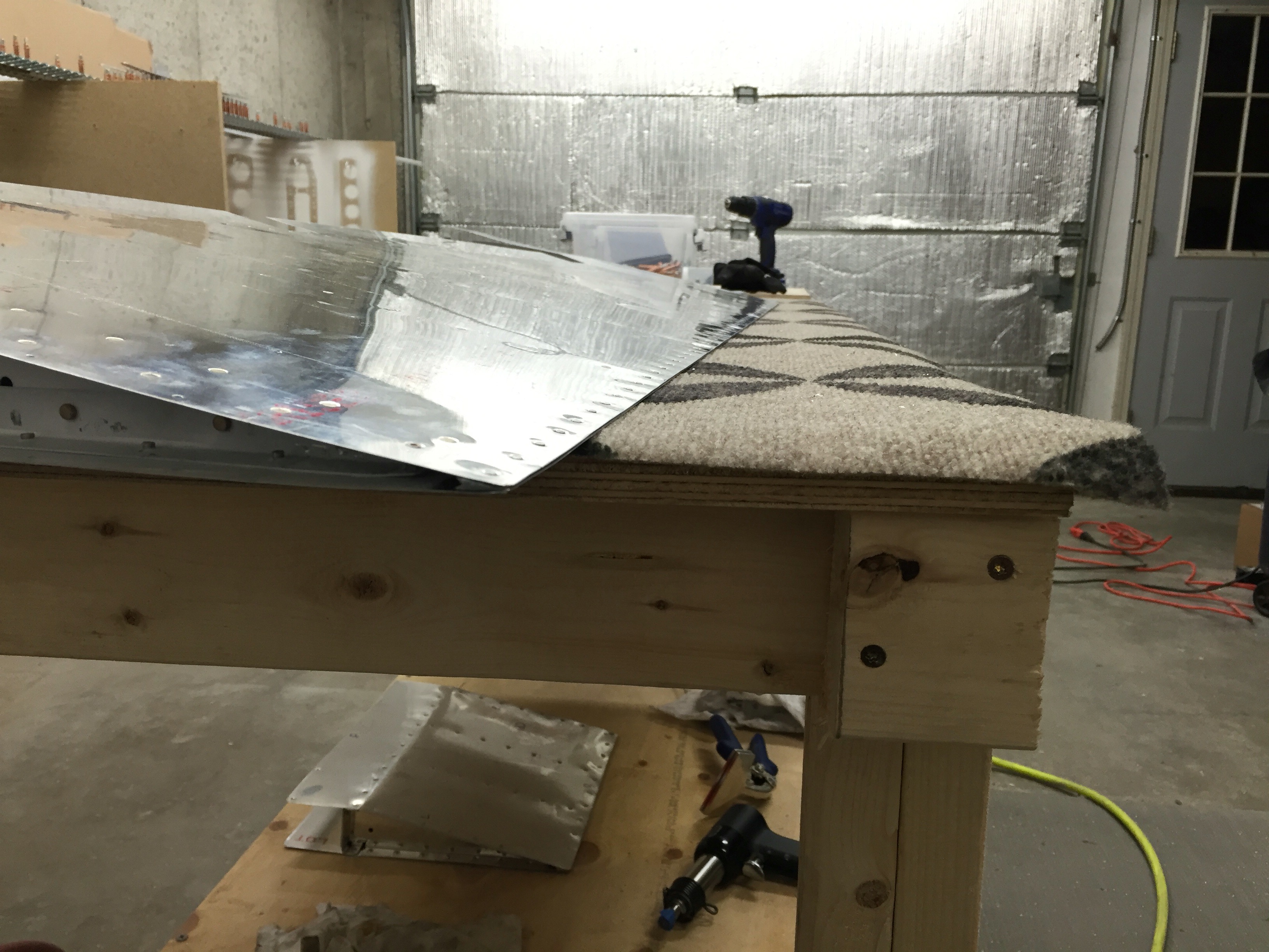
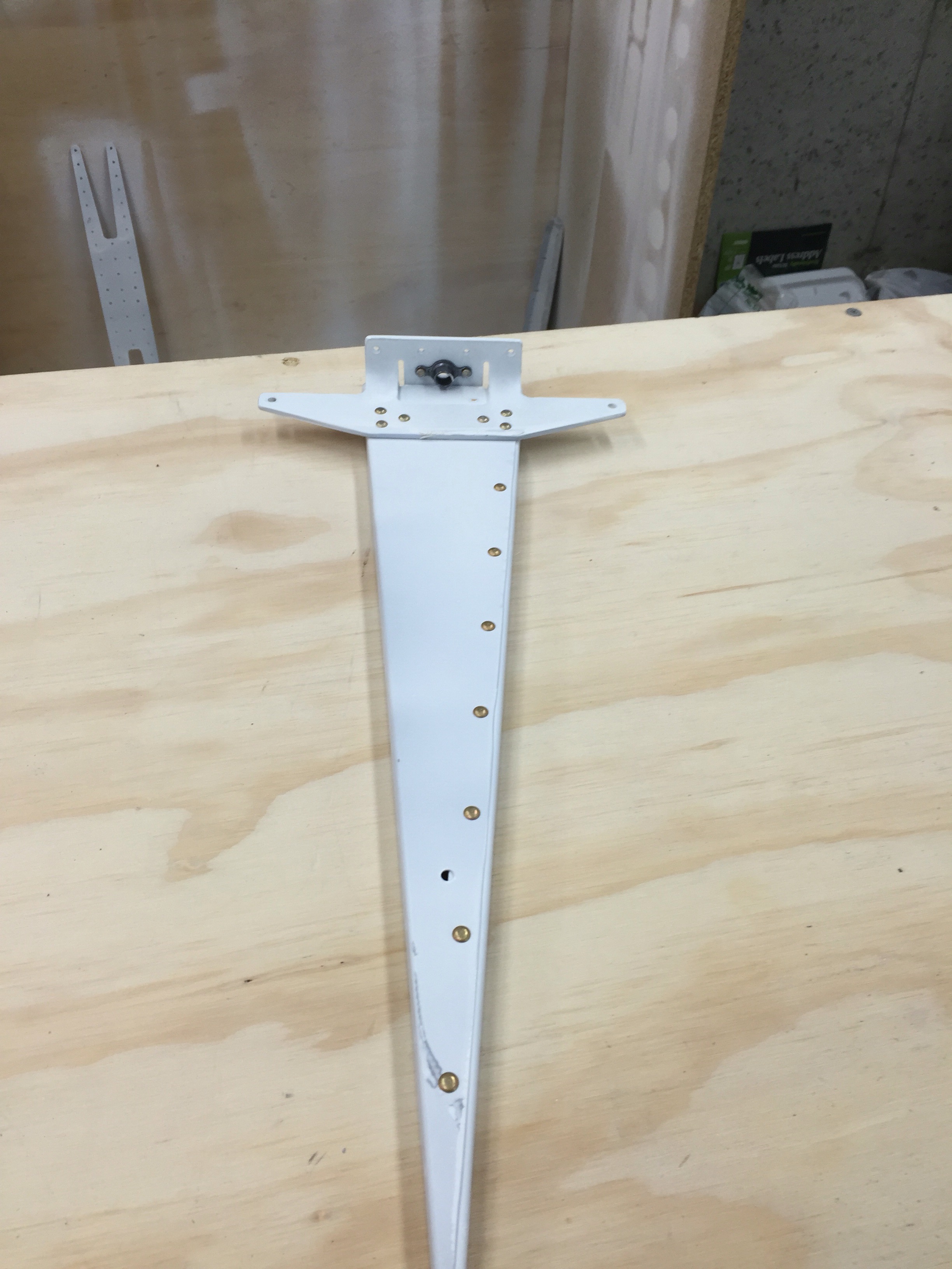
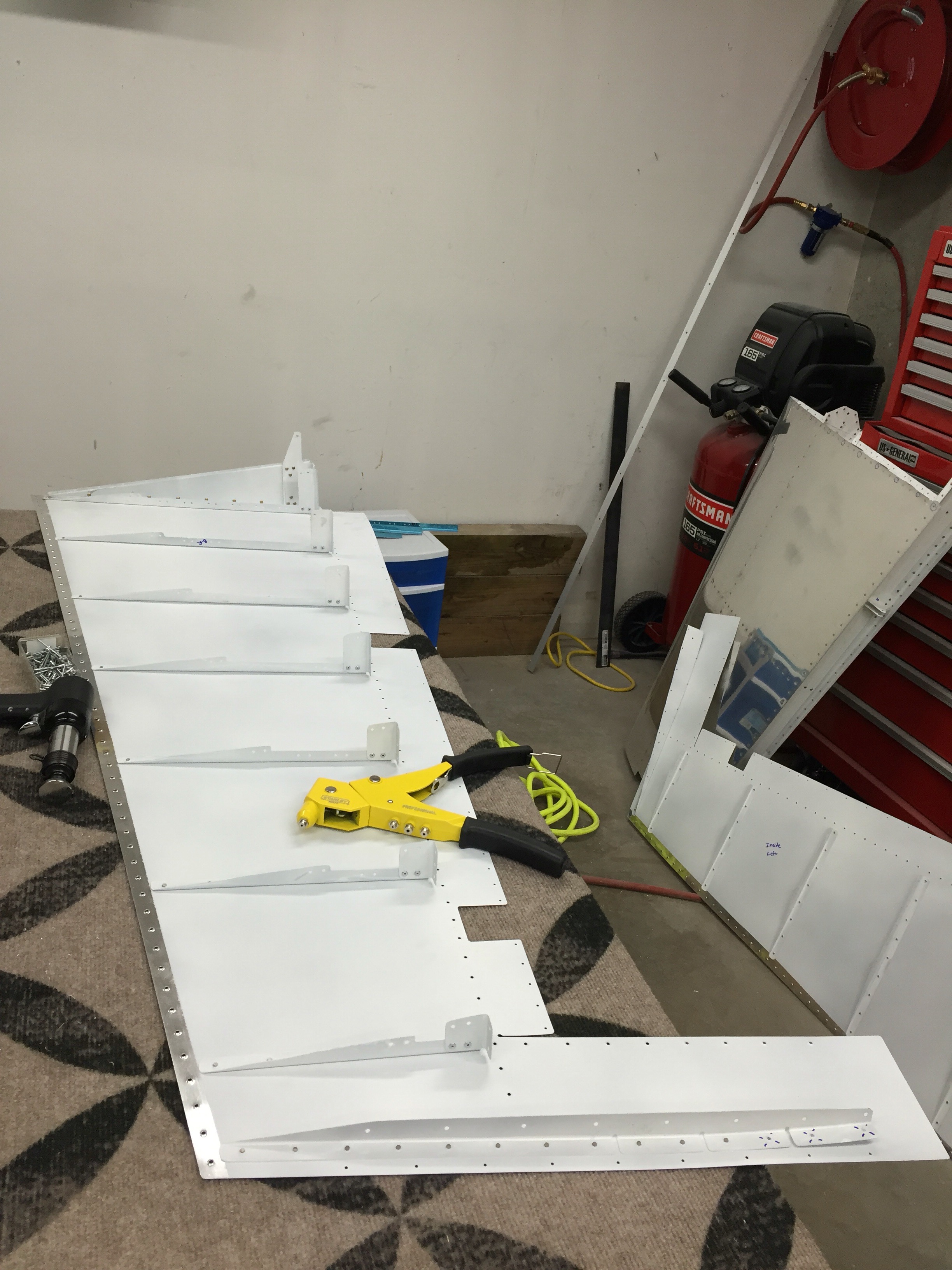
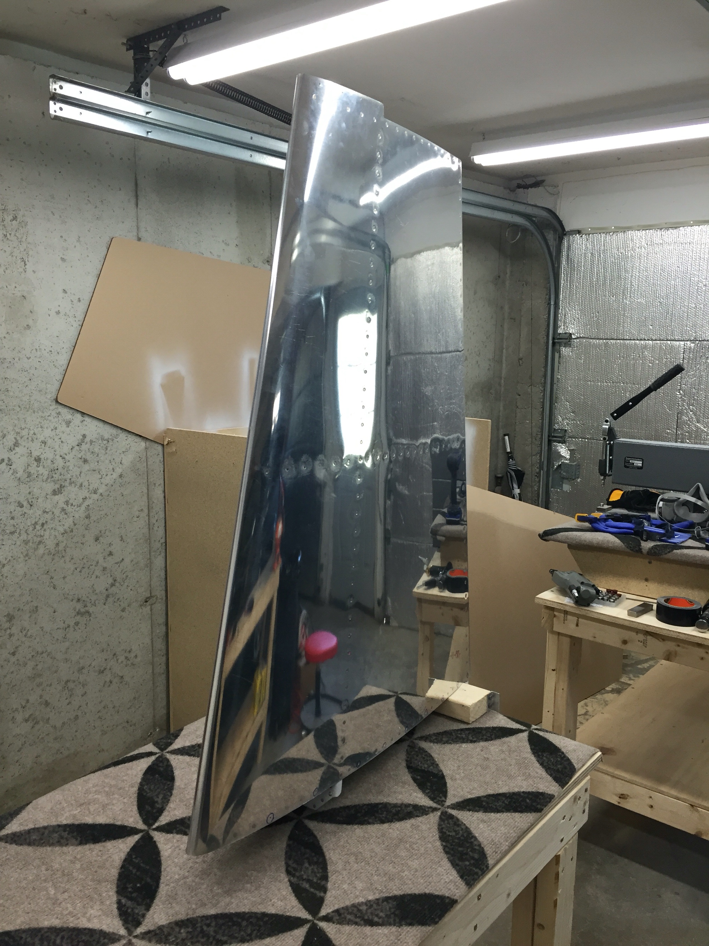
Primed. Doubler and Attach Brackets Riveted onto Front Spar


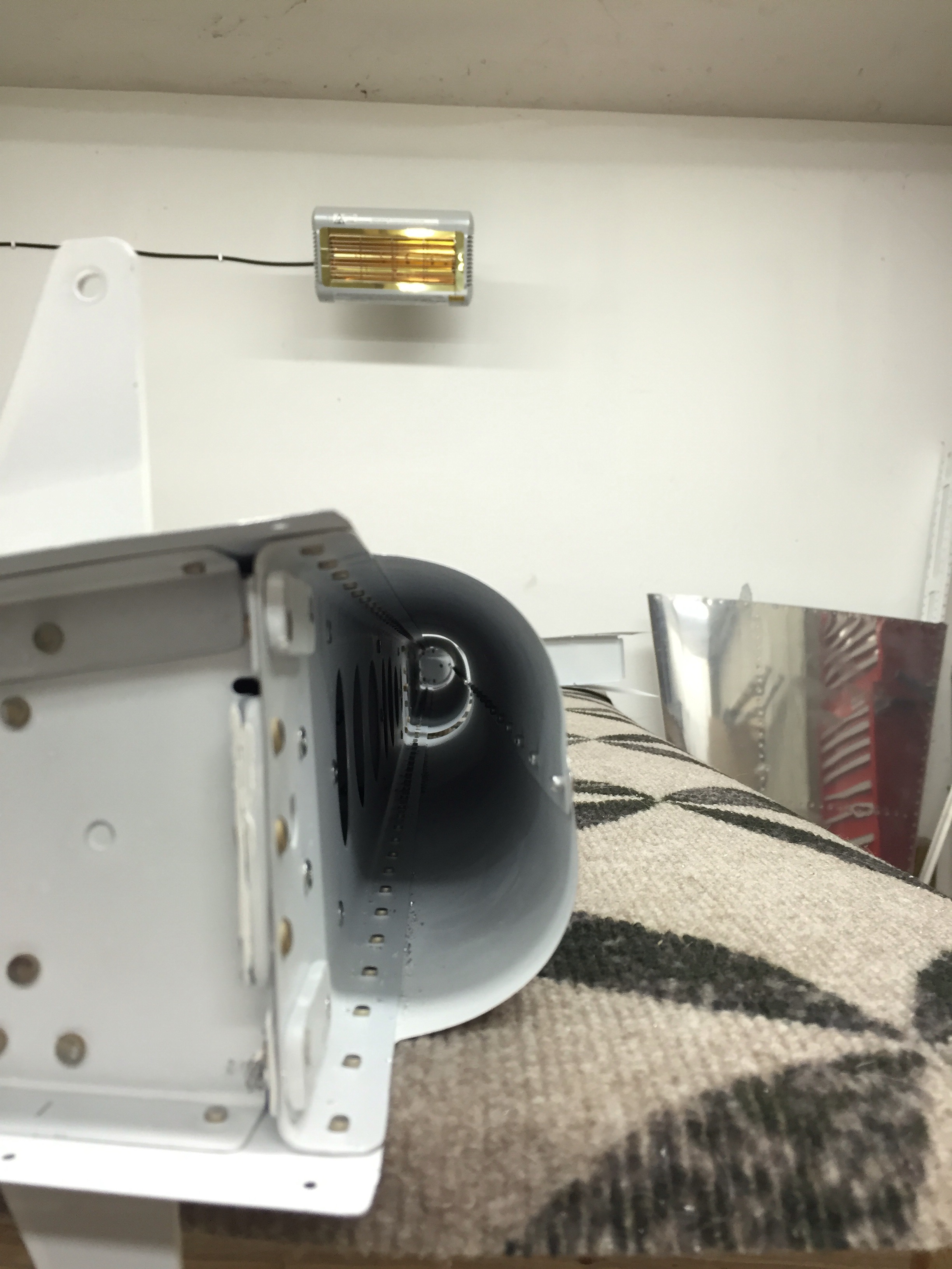
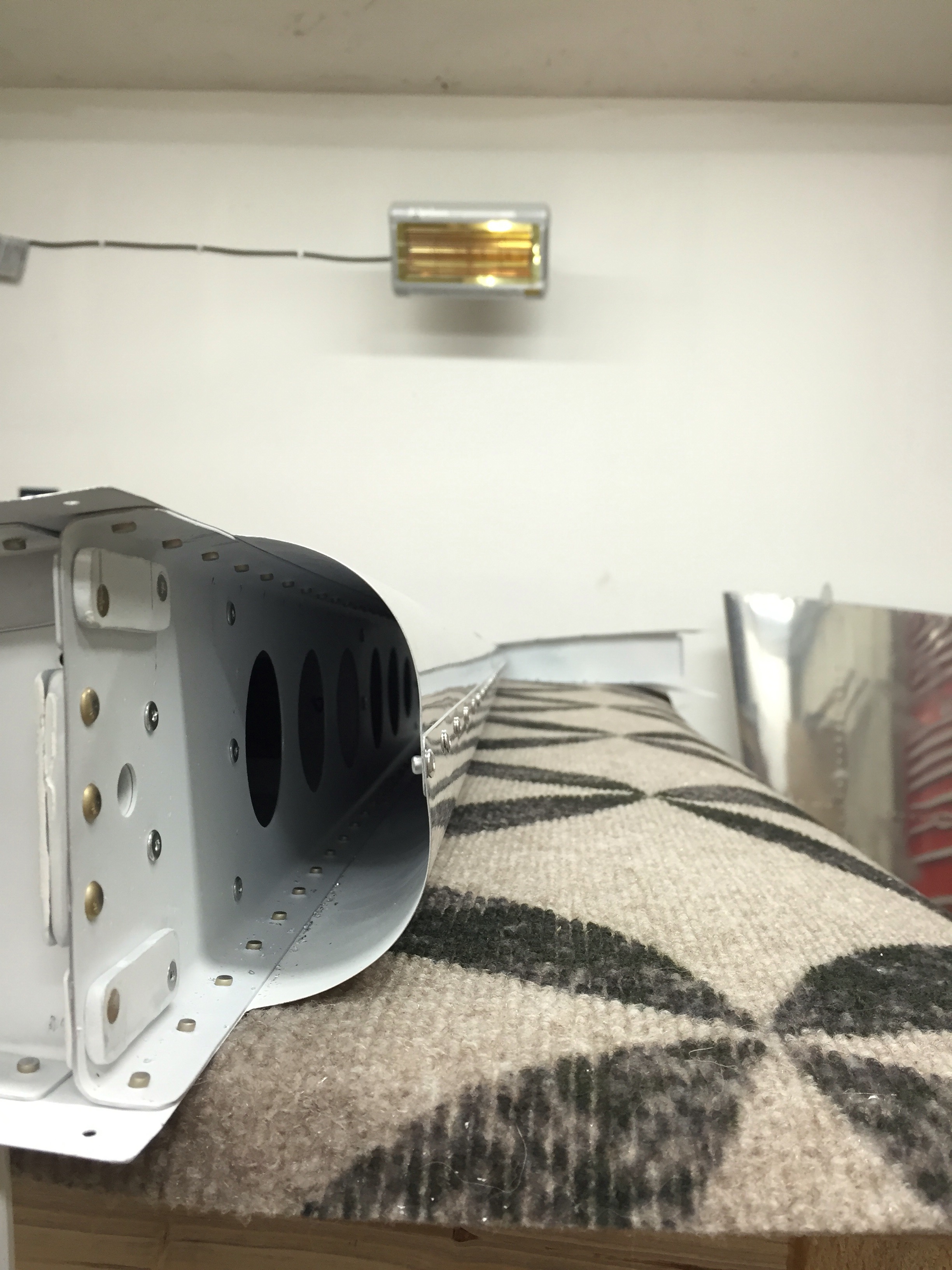
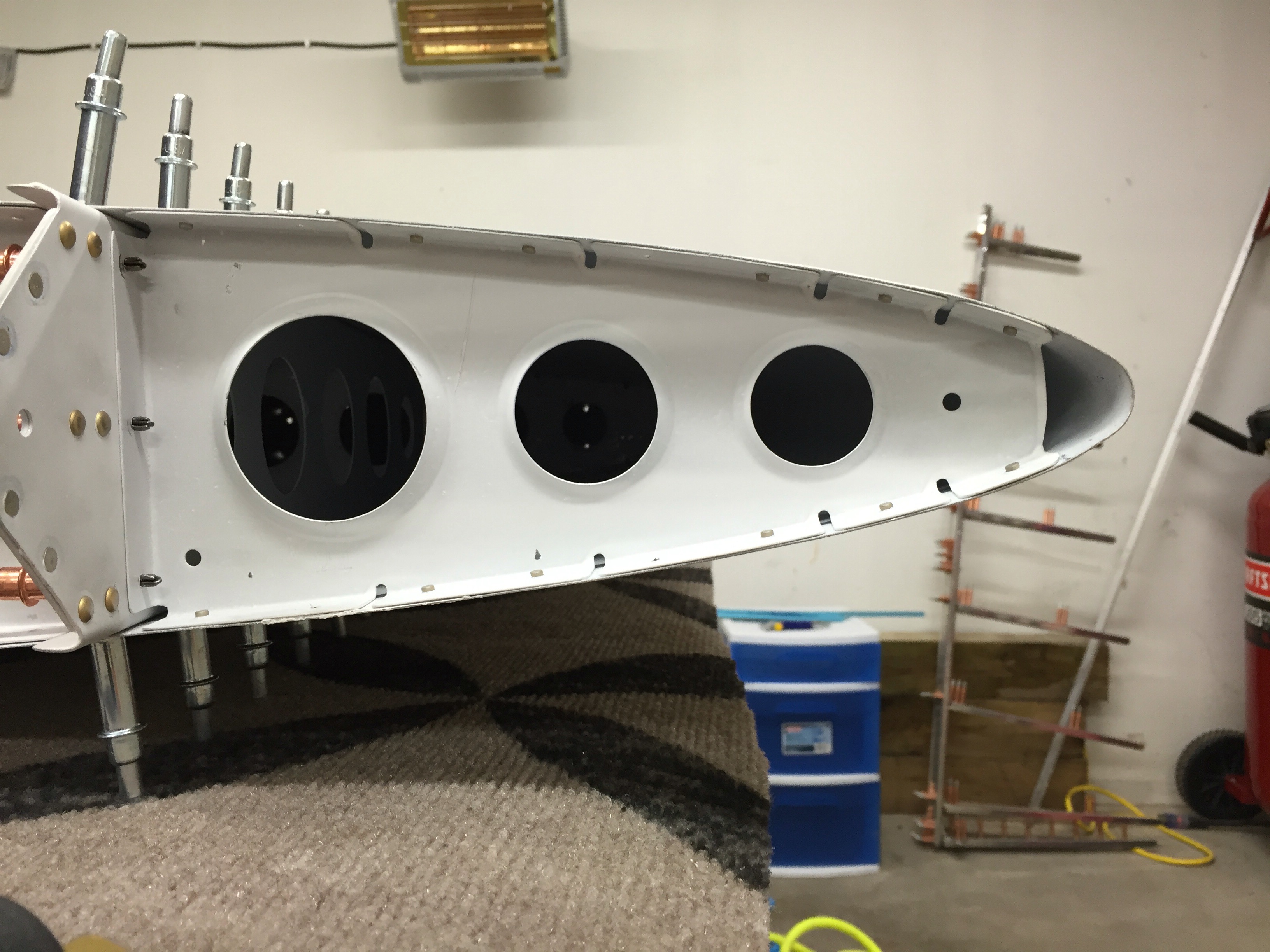
Backside View of the above Photo

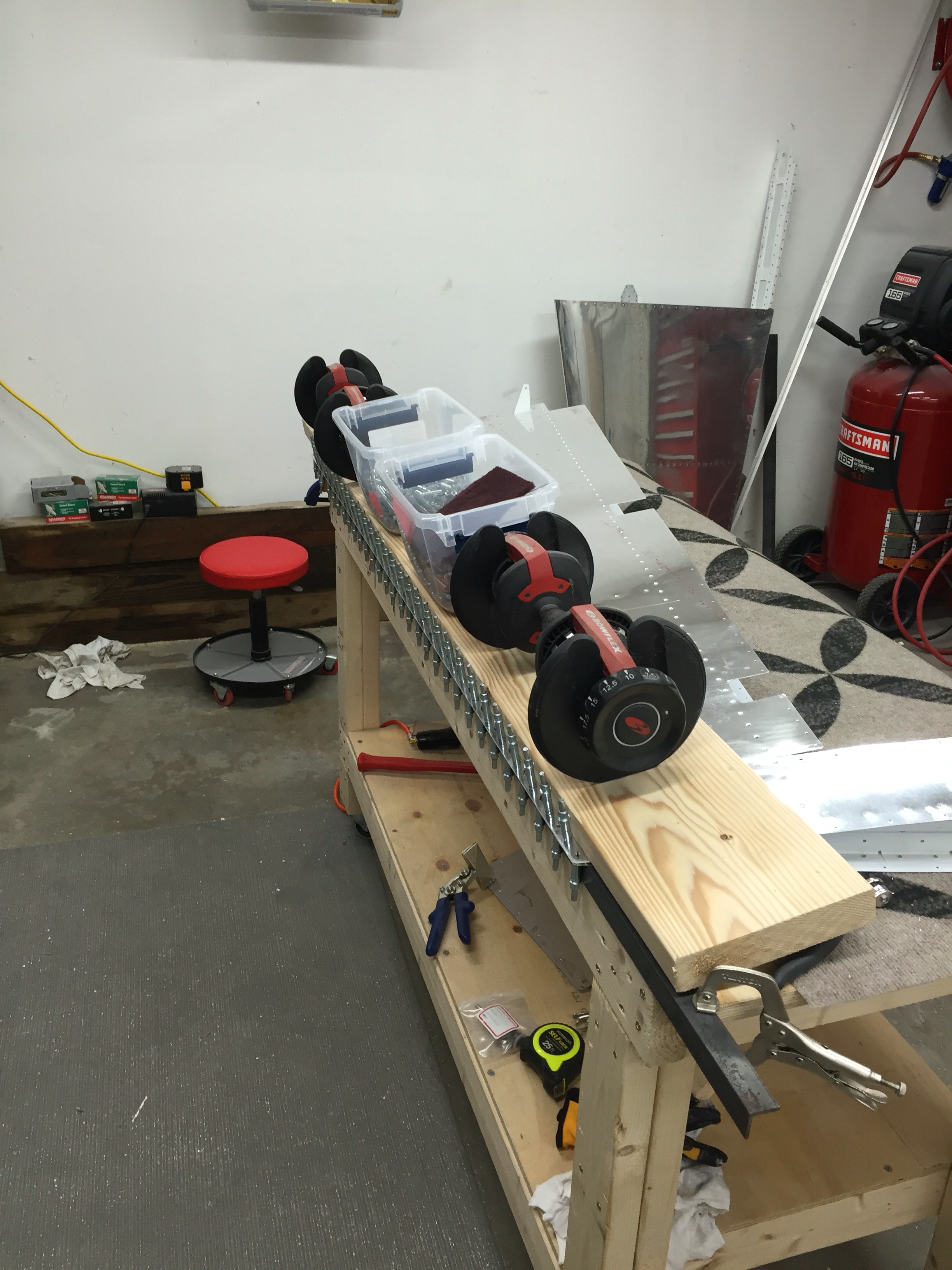
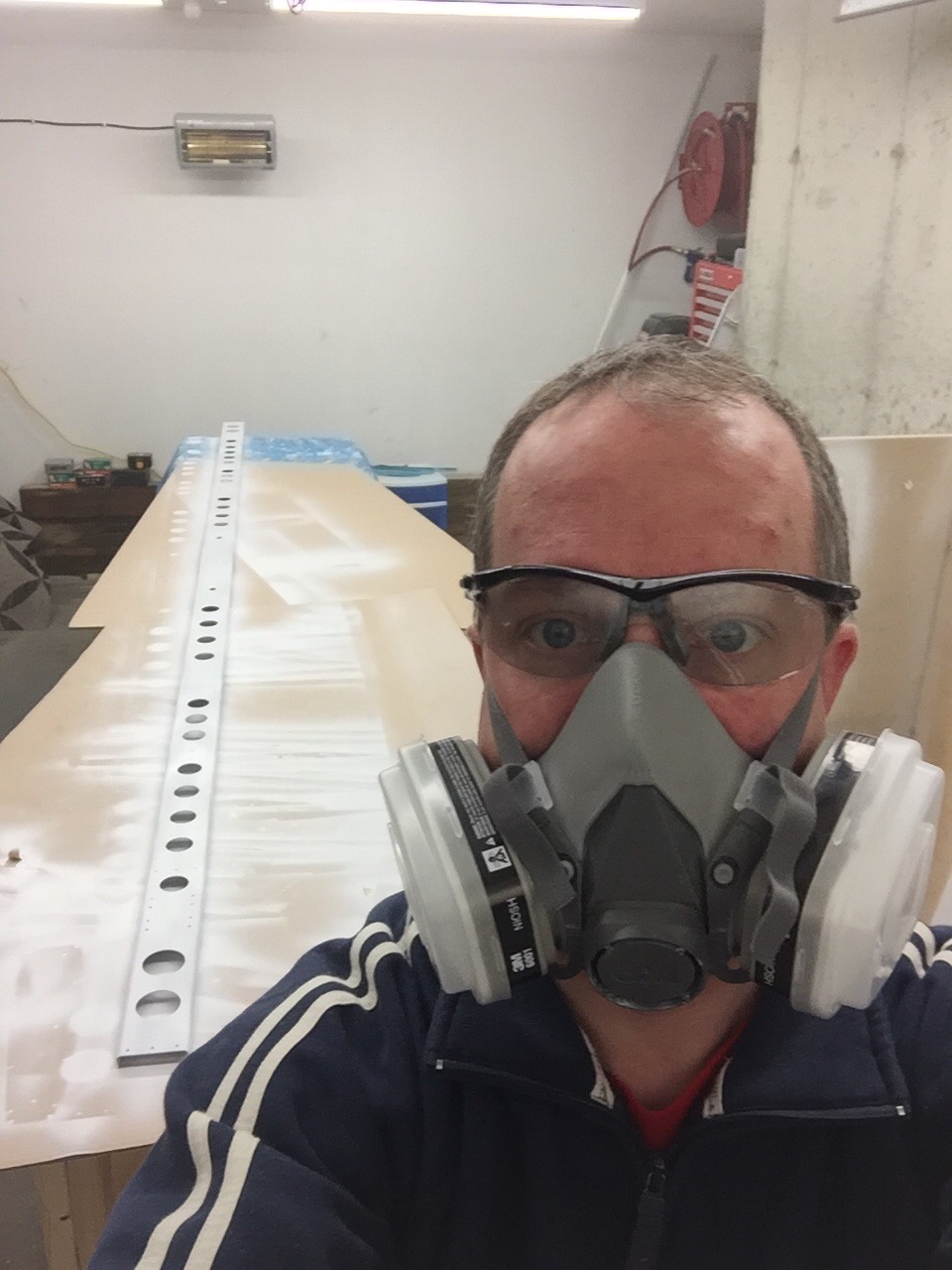
I’m now working on the tedious task of deburring the in-spar ribs and nose ribs. I really hate deburring ribs. There are so many nooks and crannies to deburr. I suppose though that if I had to make that part from scratch, that it would take a lot longer than the deburring I’m doing.

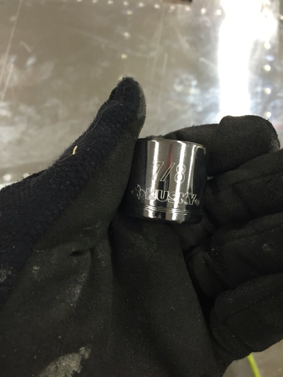
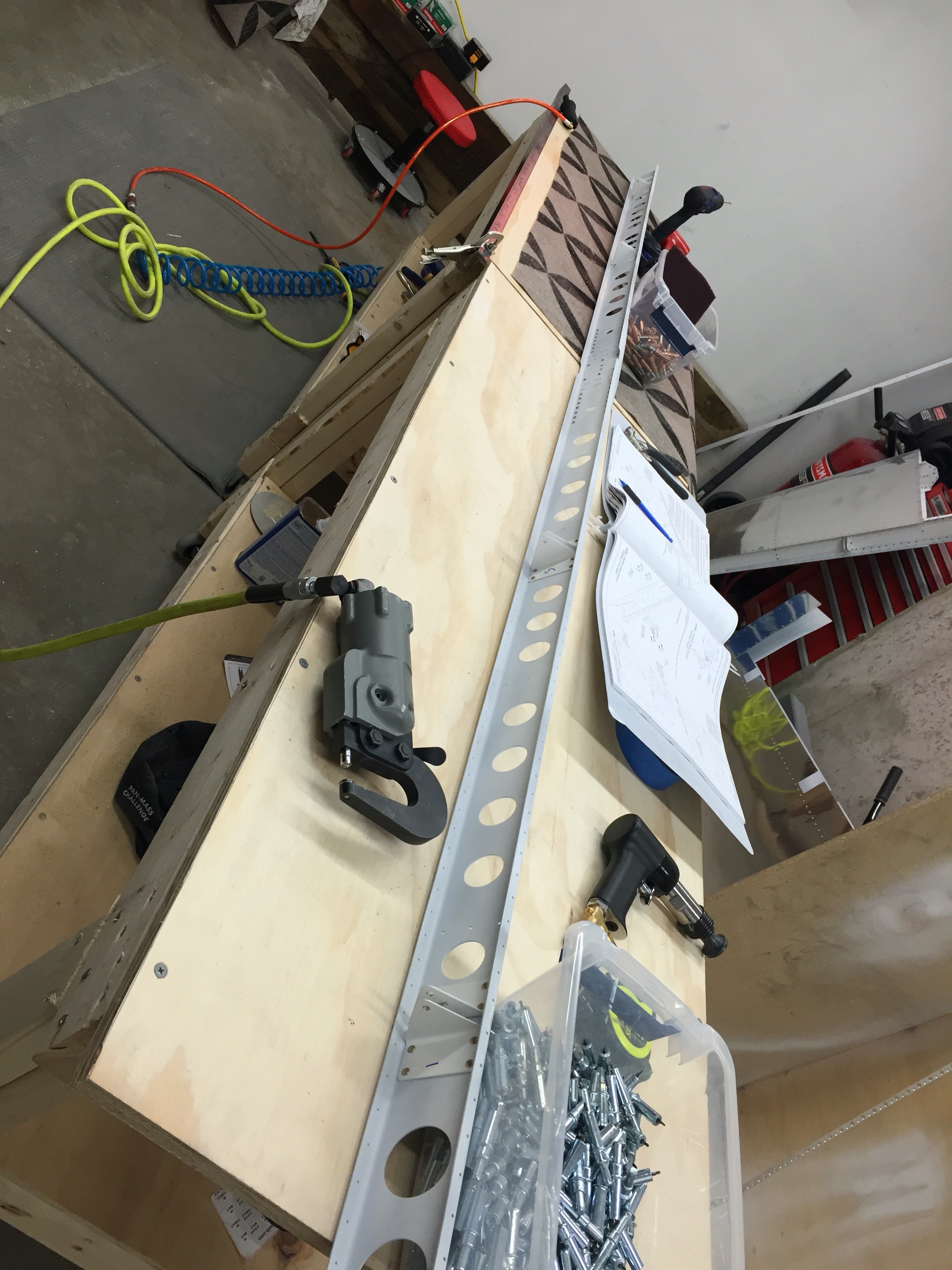
Also, while riveting the front spar, I managed to trip over my air line and pull my squeezer off of the bench onto the floor. The result was the trigger pin jammed in the on position…

  I emailed Isham, my tool vendor, and he got back to me almost immediately. It ended up being a simple fix. I removed the air swivel input, spring, and pushed the trigger pin out. Ran a reamer though the hole to get rid of any oblonging, and oiled the trigger pin back up and re-assembled. Seemed to fix the issue, and was able to use the squeezer to finish up the spar.

Rudder is Done!

The last 2 nights I spent rolling and riveting the leading edges, installing the counterbalance weight, and finishing the last few rivets on the front of the skins.

The rolling of the leading edges was made pretty easy with the tool that I mentioned in my last post.


Didn’t take any pictures of the counterbalance weight, but some obligatory pictures of the rudder and the rudder/vertical stabilizer combo.


Rudder Trailing Edge

I spent some time today getting the top rib riveted along with the skins to the main spar. The counterbalance rib was riveted on next. Then it was time to move onto the trailing edge of the rudder and riveting a “double flush” rivet. Essentially a normal flush rivet where the shop head is set in a dimple and set flush to the skin on both sides.

I ended up using my pneumatic squeezer to partially set each of the rivets along the trailing edge. Starting in the center and working towards the outside edges, I partially set every 10th rivet, then every 5th rivet. This kept on until all rivets were partially set. I then used a flush die set in a C-frame rivet set holder in my rivet gun to finish each shop head flush to the skin following the same pattern that was used to partially set them. All the while making sure that there was no bowing, hooking, or pillowing of the edge going on. An overview of the technique below:

2016-04-16 21_09_42-RV_10_CO

I’m not 100% happy with how it turned out, but that’s just the perfectionist in me. The results were a relatively straight trailing edge.

Shop Heads Flushed to the skin in their dimples

Next up is rolling the leading edges. The idea here is to tape the metal to a rod and roll it upwards creating a nice even bend in the metal.

2016-04-16 21_37_14-RV_10_CO

I recently read on Van’s Air Force a tool  that Eric, a fellow RV-10 builder, had created to make this job easy. I decided to give it a try, so in preparation to do that, I spent some time fabricating this tool from some closet rod, two 3/8″ drive sockets, and JB Weld that I bought from Home Depot.

I had purchased 1.25″ diameter closet rod, as that is the size suggested in the RV-10 plans, and 7/8″ sockets, which fit perfectly inside. I cut the rod to match the length of each leading edge section to roll. I also drilled some holes in the closet rod end and also used the grinding wheel to scruff up the sockets for better adhesion of the sockets to the rod.


Once this dries overnight, the idea is to use two 3/8″ drive socket wrenches in each end to easily roll the metal taped to the rod.

Back to the Rudder

The 3M VHB tape from Van’s showed up this week, so I was ready to start back on the rudder again. Thankfully, this time the tape VAN’s sent worked like a charm. This further validated that the tape I got from Amazon was junk. The night that the tape came in, I adhered it to the trailing edge wedge piece. Tonight I attached the wedge to the right skin which sits flat on the table. Clekos were installed from the underside of the skin in the trailing edge at the end of each stiffener. I then got my wife to help me as we rolled the left skin onto the right skin, stopping at each stiffener location to finish the internal riveting of the stiffeners and shear clips, peeling back the 3M tape on the top of the wedge piece as we went. Once this was done, I finished riveting the lower rib to the skin, and installed clekos in the rest of the holes of the trailing edge in an alternating fashion. I clamped a 6′ steel angle to the edge of the table to give a straight and uniform edge. Finally, I put a wide board over the skin with some weights on it to hold it down and let the surfaces bond to each other. I’ll leave it overnight like this. Good progress tonight!


First Part Reorder

Was bound to happen sooner or later. Friday night I started fabricating the Spar attachment brackets from a piece of Aluminum Angle.

HS spar attachment bracket

The first one (left one shown here) came out fine. It seemed to take about an hour to do one of these to be accurate. Today I started out making the right one, which is basically the same, but flipped in orientation. The first mistake was cutting the “mitered” edge which starts from a width of 1 21/32″ in the front to 1 1/2″ in the rear before I had cut the bottom leg down to 1″. I ended up with a final width only 2/32″ wider in the front compared to the rear….  Second mistake happened while cutting the other leg down to 2 3/8″. I didn’t get a straight cut, and ended up with a crooked edge. At that point, I decided to scrap that part and seeing I didn’t have enough angle left to make another attempt, I’ll need to order a new one. A 12″ long piece is $9, so not too terrible.

The stock aluminum angle to make these parts from:

  Here is the good one on the left and messed up one on the right 


I was then able to get the forward spar and spar caps cut, deburred and drilled. I also deburred the spar doubler before calling it a day. 


Also the VHB tape I got on return from Amazon did the same thing as last time. So I’ve returned those rolls and ordered some from Vans. Hoping that will work so I can finish up the rudder that is on hold at the moment. 

HS Update

So while I wait for my replacement roll of 3M VHB tape from Amazon, which actually came today, and at first look, seems to behave better than the first roll I got…. I riveted together the rear spar, stiffener, and hinge brackets of the Horizontal Stabilizer. I was also able to assemble and rivet together the inboard hinge bracket and bearing assembly. Some pictures of the progress…


Rudder Riveting and 3M VHB Frustration

Spent the day today riveting a good portion of the rudder.

First up was riveting the lower rib together, followed by adding a nutplate to the rudder horn, then riveting the horn to the bottom rib.


Then I riveted the stiffener plates and their associated nut plates onto the spar (no pictures of this)

Then we got to back riveting the stiffeners onto the skins. This went relatively easy.

Then I riveted on the bottom and top ribs along with the stiffener clips to the right side skin.

Then I came to the part where you bond the trailing edge of the rudder together. This is a relatively important step as getting a straight and true trailing edge is one of the more difficult things to do. The first step in the process is to bond the trailing edge together in prep for riveting. Bonding has helped a wide range of builders achieve good results. Traditionally, this bonding was done with Proseal; The messy fuel tank sealant material. Downside is it has a limited working time, is messy, and takes several days to cure before you can continue. VAN’s has suggested a new method using a double sided tape adhesive, namely 3M F9460PC VHB. I picked some up off of Amazon a couple weeks ago so I had it ready for when I came to this step. I prepped the surfaces to make sure they were clean, then made a couple of attempts of attaching the tape to the trailing edge wedge piece. I got frustrated rather quickly as the tape just didn’t seem to be cooperating. The adhesive had a tendency to stay stuck to the main roll of tape rather than staying on the piece I was pulling. If I got a good piece of tape going, it would quickly come to an end as the adhesive would start to stick to the main roll and pull off of the piece I was pulling, putting me back to square one. This left me with some areas that were fine, followed by area that had no adhesive at all. I got frustrated pretty quickly, and decided to call it a day after quite a bit of progress. I really don’t want to mess this step up and rush or do it half-assed without the proper materials. Pictures below show the adhesive (shiny material) completely left behind on the main roll of tape, as well as its tendency to pull off the piece I was working with and sticking to the main roll again…


So tomorrow I will see if Vans thinks this is a case of a bad batch (or past its shelf life) of tape and re-order some, and maybe even order a small amount of proseal as a backup depending on what they say. In the meantime, I can start riveting the initial pieces of the HS while I wait for something to ship.

More Rudder Progress; Horizontal Stabilizer Start

Over the last week, I’ve managed to get the skins on the rudder, match drilled, everything taken apart and deburred. Today I was able to take all of the parts to the bath tub to prep them for priming. About 2.5 hours later, I was priming all the parts. I wasn’t that happy with the priming on the VS, it didn’t adhere real well in some spots. I made a point to scuff up the surfaces better this time, as I don’t think I did enough of that last time, and didn’t give a good surface for the primer to stick to. I also bought a case of better Scotchbrite pads from Amazon for the job, plus I only have a couple of maroon pads that came with my tool kit, so I’ll need more anyways. After the prep today all of my parts were dull looking, skuffed up pretty well, no shiny surfaces remained. We’ll see how this session of priming went and decide whether I need to buy some etching solution as an additional step prior to rinsing and priming the parts.

A couple of pics of the rudder as I was preparing to match drill all the holes common to the skin and the skeleton.

Like before, while waiting for the rudder parts to dry enough to flip and spray the other side, and dry again, I decided to start on section 8; The Horizontal Stabilizer.

I got the rear spar, stiffener, and Hinge Brackets deburred, match drilled, taken apart and holes deburred. I was rather surprised that at such an early stage (page 1, in fact) that the instructions tell you to prime the parts you just worked on, as we’re going to start riveting them already.. Okay… So I prepped the parts in the tub again, a bit of a challenge with the spar being so long (see the picture below), and let them dry as I took a break for dinner. I actually needed to butt the two work tables up against each other for the first time, as this is a pretty long part. The tables are 5 feet long each, so this part is a little over 10′ long.

A quick “selfie” in my garb after finishing the primer coat on the Horizontal Stabilizer Rear Spar.

Tomorrow I should be able to start riveting the Rudder together once the parts cure overnight.

Vertical Stabilizer is Done!

I had Good Friday off from work (a new holiday in the acquired companies calendar) which allowed me to spend 2 long days finishing the Vertical Stabilizer!

A real airplane part is now complete. Certainly was interesting reaching into/underneath the skin with one hand while trying to rivet with a flush set in the other hand. Especially connecting the upper portion of the skin to the forward spar. Here you have to remove just enough clecos to bend the skin upwards to slide your hand/arm underneath to hold the bucking bar completely blind. Luckily I had quite a few to buck prior to that so I got a good feel for how to hold the bar with equal spacing on all sides. It actually went better than I expected.


Time to keep making progress on the Rudder.

Vertical Stabilizer Assembly and a Mistake

Once all of the primer dried, it was time to start assembling the Vertical Stabilizer!

I got started by putting the rudder stops on the bottom-most rudder hinge.

The next step was to assemble the spar, doubler, stiffener plate, and the remaining rudder hinges.  Here I am doing that step.

Once that was done, it was onto riveting the spar pieces together. My pneumatic squeezer made quick work of that.


Next up, was putting the skeleton back onto the spar and riveting some of the upper ribs to the spar. Once that was done, I cleoco’ed the skin onto the skeleton, and started to rivet the forward middle rib and skin together. I got one side done, and after flipping it over, I got the the 4th rivet and decided I needed to drill that one out. I drilled the head out and started to use my punch to push the shank of the rivet through. Once the shaft let loose, it caused my punch to go through the skin hole and bend the flange of the rib behind  it. SIGH!

Of course, looking at this picture, I realize I need to put some tape on my bucking bar, or be more careful to not scrape it on the rib edges. It’s taken off a bit of my primer.

So I drilled out the rivets that I had completed on that side and uncleco’ed the skin to open it up. I was able to bend the flange back into a reasonable position that should work. Being a bit concerned, I also contacted Van’s support to ask if they thought it was okay to build on or stop and order a new piece. I was pleased when about a half hour later, they responded that it doesn’t look like it bent enough to cause work hardening and to bend it back and carry on. Here are a couple of pics of it bent back mostly into position.


I was then able to close things back up and re-rivet the rib. I also completed the froward parts of the top and bottom ribs as well.


   More work on finishing up the VS this weekend.