Electrical Architecture

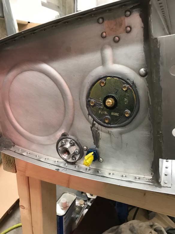
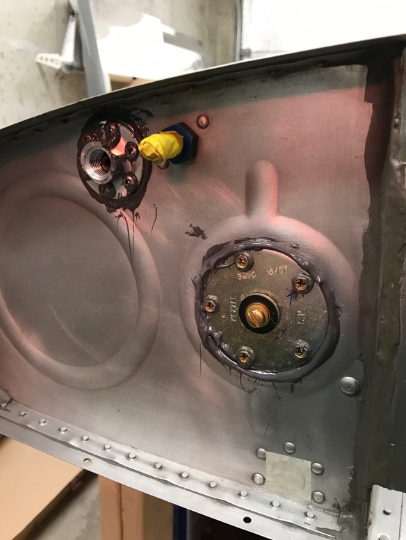
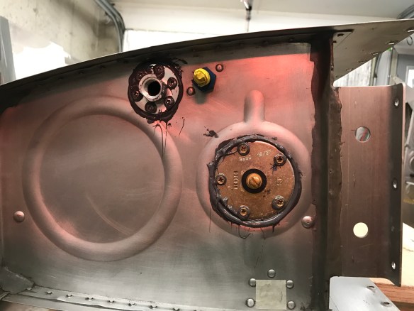
As I’ve mentioned previously when putting a fuel return port into my gas tanks, I plan to go full EFII (Electronic fuel injection and ignition). That means I’ll have an electrically dependent airplane and, being such, demands quite a bit of attention to the electrical architecture to have redundancy to always keep the fan turning. Fortunately, there is a guy by the name of Bob Nuckolls over at the AeroElectric Connection who has written a book outlining basic electrical principles (most of which I already know being an EE), and provides multiple different time-proven architectures having worked in the industry for many years.

Early on, I had really settled on his Z-14 architecture, which is a dual battery, dual alternator, split (redundant) bus architecture. In-depth schematics are located across 2 pages here and here for those interested. This allows one to take approx half of the load and run it on one bus independent from the other. The idea would be to have the left glass panel, #1Nav/Com, and a handful of other goodies on one bus, and have the #2 Nav/Com, the right-most glass panel etc.. on the other bus. That way you should always be able to navigate, communicate, and get on the ground even under IMC conditions. Additionally, the EFII system is redundant too in the sense that there are 2 ECU modules, 2 fuel pumps, 2 ignition coils, etc… so each of those would be powered off of their respective redundant power busses such that you always have power to at least one of the redundant pair. The 2 busses also have the ability to crossfeed, meaning that if a failure occurs which takes out one bus, it’s possible to continue to use it by having the 2nd bus feed it. That feed won’t be at the same overall capacity as you are now on a single battery and alternator, but most stuff should be able to be used after doing some non-critical load shedding.

I’m getting close to pluming in my brake and fuel lines and systems so I’ve recently started researching more details into the architecture and also the SDS EFII solution I have chosen. First off, I’ve ordered the Andair duplex fuel selector that I’ll need to both select and return  fuel from one of the tanks.

fs2020-d2-1

Duplex fuel selector

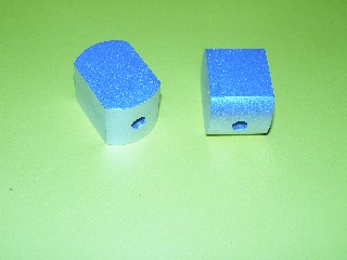
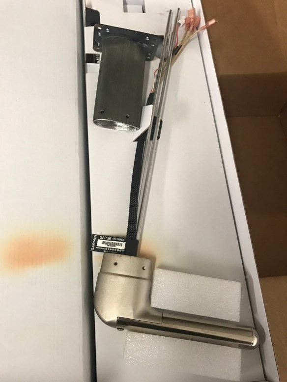
I’ve also placed an order for my dual fuel pump module (shown below), filters, and pressure regulator.

fuelpump25

Dual fuel pump

One thing that I have discovered is the fact that there is only one set of injectors into each engine cylinder for the fuel injection (i.e. not redundant), so there becomes a need to be able to power those devices from either battery. I was figuring that I was going to need to diode-Or the two battery busses together in order to accomplish that. Fortunately there was some really good discussion on VAF about this very topic and various architectures for an EFII setup. The end result was a slightly modified Z14 architecture that provides just that. I am currently planning on going with this as the architecture for my plane.

basic z14 arch

Z14 Electrical Architecture with addition of Diode-OR’ed Engine Bus

Credit for the diagram goes to Dan Horton.

Ignore the alternator amperages for now. I will need to work out my exact electrical loading and size everything appropriately.

Talking to the architecture diagram, you have 2 separate batteries that provide their respective battery busses. These feeds are directly off the battery. The battery busses are then joined together via switches and diodes to form an Engine bus. One could simply put the fuel injectors on this engine bus and keep all the other redundant engine components on their respective battery busses, but the point was made that once you have to have an engine bus, you might as well put all critical engine components on it. The switches would provide a way to isolate the engine bus from either side if something really bad happened on one of the sides that it was impacting the engine bus somehow.

The upper part of the diagram shows each battery feeding a a main and aux contactor (what your master switch typically turns on) powering a main and aux bus which all of the other electrical devices will sit on. There is the cross-feed (cross tie) contactor which allows one bus to drive the other, and each bus has its own alternator.

There will be no single point of failure that can cause the engine to shut off, if something happens, the goal of the architecture is to be able to keep flying while diagnosing and planning to get on the ground as soon as practical. Another benefit of this is if there were ever smoke in the cockpit, the first reaction will be to shut off the master switches. This is still the response here. The panel will go dark, but the engine will still run.

There is still lots of work to do on specifics, but I feel like I have a solid foundation to work from.

We have steps!

I’ve spent the last few days finishing off items on my list that I accumulated while inspecting the Quickbuild Fuselage.

One of those items was to finish riveting the forward floor boards. I had once considered spraying some insulation under the floor boards for sound proofing, but after doing some research on VAF, I’ve decided against putting any insulation there. It’s best practice to keep all insulating material several inches back from the firewall so it doesn’t get hot and burn/smoke/out gas in the event of a fire. There’s just no guarantee that I could achieve that by spraying.

Front Right passenger foot well all riveted

The other main item I finished up was permanently attaching the steps. Most of the items in this section were already done as part of the quickbuild, all I had to do was slide the steps in and bolt them in position. One minor tweak that I did was to install bushings inside of the step tube right at the bolt hole. There have been complaints over time that the steps become loose/wiggly. The idea here is that the bolt doesn’t really have much to tighten against as it’s basically just going through the center of a hollow tube and crushes it (makes it oval instead of round) when tightening. So TCW Technologies came up with these perfectly sized bushings to insert into the step tube and give the tube some rigidity right at the bolt hole.

Here’s a picture of the bushings:

OLYMPUS DIGITAL CAMERA

Here are the installed steps:

Left Step

Right Step

Both Steps from behind

Back at it!

Today I pounded some rivets! Felt good to get going again.

I managed to put the baggage door shims and floor angles on both sides. I also drilled out a few rivets and trimmed the baggage door seal which wasn’t trimmed down per plans. There are certainly a few things that fall into that category on the Quickbuild kits.

November 2018 Update

It’s been about a year from my last post. It’s been quite the hectic year between raising our son, selling our home, and building our new home.

Declan is now almost 16 months old. He’s now walking around (okay running most of the time) getting into lots of trouble. He really is a pretty happy guy most of the time and is developing well. His length continues to be in the >97th percentile. He says lots of words, and even has started putting 2 words together. He’s also started daycare part time so my wife has been able to increase her work hours from 2 days per week up to 4 days.

We de-cluttered and listed our home, put the airplane project in storage :(, and sold our home on the first weekend it was on the market in Mid-May. There were a bunch of delays actually closing with a couple of home sale contingencies,  which worked out in our favor seeing we had no place to live otherwise. Eventually though, we closed on September 17th and now have that chapter of our lives behind us.

As I write this, we are still in between houses. The new house is done and we are just waiting on the “Cleared to Close” indication from the mortgage underwriters. It’s been very frustrating to have a house ready to move into and we can’t close for a number of reasons. The first was there is a law that says you have to be given the Closing Disclosure at least 3 days prior to closing, the other is that due to all the delays, our file with the mortgage company had expired and it seems they had to re-review everything again, taking some additional time.

We should be closing this week (week of Nov 4th) either on Tuesday or Wednesday. After re-reading some of my blog, and hanging out at the airport yesterday and talking about RV building, I remember just how much I miss actively building. I’ll be very much looking forward to getting settled in our new home and get building underway again.

New House.. Almost done.

Declan’s 2018 Costume

Halloween 2017 Update

Our son, Declan, was born on July 13th.. He’s now 3.5 months old and doing well. Jeanine and I are adjusting well to parenthood.


Since then it’s been pretty difficult to find time to work on the plane. So there’s really no update on my plane progress. This was part of the reasoning for going the Quickbuild route. I’m way further along than I would be otherwise.

I’ve recently have felt like I could have spent some time here or there on the plane, but have been a bit distracted by house projects and getting it ready….

Ready for what you say???

Jeanine and I have always talked about moving to a new house. Specifically, we don’t like our lot. It’s more of a side-to-side lot, with no back yard and near a busy main street with little privacy. If it were just us, we’d probably just stay where we are. We like our neighborhood and neighbors, but with the addition of Declan, we’ve started thinking about it more again. We really weren’t thinking of looking seriously until spring at the earliest, but we found some new construction in our town about 5 minutes away from where we currently are. The timing of such works out that it wouldn’t be done until spring anyways. That’ll give us time to finish a couple of outstanding projects and literally “clean house” prior to putting  it on the market in the early spring.  Some of those projects are done or in process. We’ve been working with an architect to come up with a design, which is now finalized. We’re waiting on the builder to provide the final pricing based on the plans and get final financing commitment prior to breaking ground sometime in late November or early December. The new house will have a 3 car garage; 34’x24′ in size, of which 2 bays will be my new airplane factory. That’ll provide much more space than the single bay I’m working in now, and should allow me to keep the plane at home until much later in the process.

So very exciting (any busy) times ahead, so plane building will take a back seat for the next few months so that we can work on getting this house ready, planning finishings etc… for the new house, as well as care for an infant. 🙂 In the end it’ll be a welcomed delay to be in our forever home. After that, the airplane build can commence.

Here are a couple of profiles from the plans…

Aileron Actuation and Tank Leak Testing

First step in this section is to fabricate two torque tubes which are used to push and pull on a bellcrank mounted on the spar. This bellcrank converts the horizontal motion into fore and aft motion to move the aileron up and down.

Torque tubes and end caps

Drilling holes for the end caps

End caps riveted on

Both tubes completed and aileron torque tube ends shown too.

I then fabricated the bellcrank to aileron pushrods as well as the start of another set of aileron torque tubes which sit at the root of the wing and partly attach to bearings on the end of the gas tank. Seeing I hadn’t yet leak tested my tanks, I needed to take a break and do that, prior to reattaching them to the wings.

Leak testing the tanks is relatively straightforward. The idea is to seal off all openings, pressurize the tanks just enough (too much pressure can cause damage) and spray soapy water all over the seams and joints to see if there are any leaks. A bicycle pump valve is provided in the kit to go into the fuel drain port. This allows you to use a bicycle pump to inject air into the tank, pressurizing it. The fuel pickup and, in my case, fuel return line needed to be capped off. In order to provide a safety valve, a balloon is placed on the tank vent port and will inflate as you add air into the tank. The balloon acts as a safety valve and will pop prior to allowing too much pressure to be added to the tank.


Adding air to the tank

Spraying all the rivets and surfaces with soapy water

Of course, never doing this before, I wasn’t quite sure what I was supposed to see if there was indeed a leak. On the first tank I attached the balloon to the vent port with duct tape and a zip-tie. It clearly didn’t work very well and the slow leak exhibited itself by really bubbling up.


Balloon connection had a small leak. 

On the second attempt, I placed some fuel lube inside the neck of the balloon, used some string to ensure a better connection, along with a ziptie. That seemed to do the trick. No leaks and the balloon stayed inflated overnight.

I then was able to reattach the tanks to the wings and am relieved that the tanks didn’t have any detectable leaks in them.

With that behind me, I was able to get back to getting the aileron control system fully hooked up.

Wing root torque tube attached. Getting ready to attach the main pushrod.

Getting ready to attach the pushrod to the bellcrank

In order to properly set the length of the tube there is a jig that is inserted in the bellcrank that sets the neutral position. One must them make sure that the hole on the arm back at the wing root is exactly 2 9/32″ from the edge of the tank to the center of the hole

Setting the tube length based on the neutral position with the W-730 Jig

Exactly 2 and 9/32″ to the hole center.

All hooked up, looking down the wing

I then started getting the actual aileron and flaps placed onto the wing to set their neutral position. It is then that I discovered that I had riveted the end of the gap fairing on the wrong way. In setting up the flap position it says that the nose of the flap should sit against the spar doubler. Well instead, mine was sitting against the gap fairing, which didn’t seem correct… I went back in the plans, and sure enough, I did it wrong. Nothing that drilling out a few rivets and flipping it around can’t solve..

That 1021B-L part is not oriented the correct way. DOH!

After drilling out 4 rivets and flipping it around. Much better, and makes more sense.

The flap is used to set the neutral position of the aileron by clamping the trailing edges together with some aluminum angle. Then with the W-730 Jig back in place to set the pushrod neutral position, the bellcrank to aileron pushrod length is adjusted so that it is perfectly fits when both items are in their neutral position.

Flap and Aileron clamped together

View of left wing with both flap and aileron installed

Bellcrank to aileron pushrod attached to aileron

W-730 Jig back in place with bolt coming through the pushrod in the upper right of the jig meaning everything is perfectly aligned.

A view looking down at the finalized bellcrank assembly. 

Fuse and Finish kit arrive

Been a bit busy finishing some hardwood flooring in the spare bedroom as well as getting the nursery ready for our little guys arrival in early July. Plane building has suffered a little bit recently.

I’ve finished the bottom wings skins as far as I’d like for now. I’ve deburred them, but will leave the dimpling for later. I’m sure I’ll be happy to have some metal work to come back to in between all the fiberglass work coming up. I’ve started on the aileron actuation section of the plans:

I’ve fabricated the Bellcrank pushrod as well as the bellcrank to aileron pushrod and primed them. Pictures of those will be forthcoming.

In the interim, I took delivery of my Quick Build fuselage and finishing kits. These pieces account for the remaining structural pieces of the kits. All that remains after these kits are the engine (and Firewall forward kit) and the avionics. Don’t let that fool you though, there is a ton of work to do on the kits that will keep me busy for quite a long time.

Fiberglass cabin top behind the fuse

Finishing kit crate

Fuselage stand I built out of saw horses and 2×4’s with casters

Lots of stuff! Cowlings, door shells, and wheel pants. 

Continued Wing Progress

Sorry for the lack of updates recently.

Since the last update, I’ve been able to get the Pitot Tube bracket all ready to install.Like a few other RV-10 builders, I’ve decided to put my Pitot further outboard as compared to plans. I’ve placed it in the 2nd to last wing bay. This will keep it out of the way of the tie-down ring/rope and any possibility of getting it caught up.

Mounting the Pitot  involved adding a piece of aluminum angle to the outboard rib such that the bracket would sit flush with the rib flange and allow the bottom wing skin to sit flush to the rib. I also used the bracket to draw the outline of the cut needed on the bottom skin. A unibit was used to cut the initial holes and then files were used to shape and debur the cut.

Making sure the bracket sits flush to the rib flange

Aluminum Angle support riveted to the rib

Using the bracket to drill the bottom skin.

All Filed clean

Testing the Pitot Mount fit through the bottom skin cut

Pitot Mast in rough place with the bottom wing skin on.

All the holes are now match drilled.

I then moved on to continue the bottom skin section of the plans.

I will finish this section up until the point of actually riveting the bottom skins in place. I plan to do that at a much later date. While things like auto-pilot servos and wiring can be done after the fact, it’ll be much better to allow access for these tasks later on.

The first part after dealing with the pitot tube, was to match drill and rivet on the gap fairings for the aileron and flaps. Below they are shown cleco’ed in place. I’ve already riveted them, but apparently didn’t take any pictures of them finished.

I’ve also got the J-channel stiffeners all in place and match drilled to the bottom skins. The bottom skins are also match drilled to the ribs and spars. All that is left for this section is to debur everything and dimple all the holes.

Wing Update

Next up was to knock off fuel tank related items so I could get to a spot where I could proseal the fuel senders and the fuel return ports onto the tank.

First I had to bend the sender rod as shown in the plans. 

Then I needed to test out the sender to make sure it can go stop-to-stop without hitting anything inside the tank. Mostly the fuel vent line is what typically gets in the way. I measured the resistance at the stops on the bench to know what values I should see. I then used a string down through the drain opening to help me pull the float up and down in the tank. I had to bend the float towards the front of the tank to get it to not hit the vent line. After a couple of iterations, I declared success.

I then started on the fuel return port. The EFII instructions only require that you place the fuel return at least 3 inches away from the feed line to prevent bubbles from fuel being returned to the tank from being picked up and sent back into the feed line. After reviewing some posts on VAF, and seeing multiple other people put their fuel return lines in a spot that would interfere with attaching the tank and the wing to the main spar, I decided the best spot was just forward of the vent line port. Several others ended up with similar placement. Once the spot was decided, I had to drill a 0.5″ hole for the center AN fitting and surrounding holes for the screws which help prevent rotation of the bung.

img_8731img_8730img_8732img_8734

I’ll let this sit for a while to cure, then it’ll be time to leak test the tank.

I was also able to enlarge the holes in the wing ribs to 3/4″ to accept conduit for my wire runs. I also added a second 7/16″ hole to run a second static line to my Pitot tube for its AOA function.

Garmin GAP26 Heated Pitot Tube and Mount


Static lines and conduit routed