Aileron Actuation and Tank Leak Testing

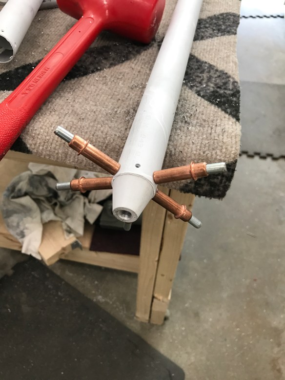
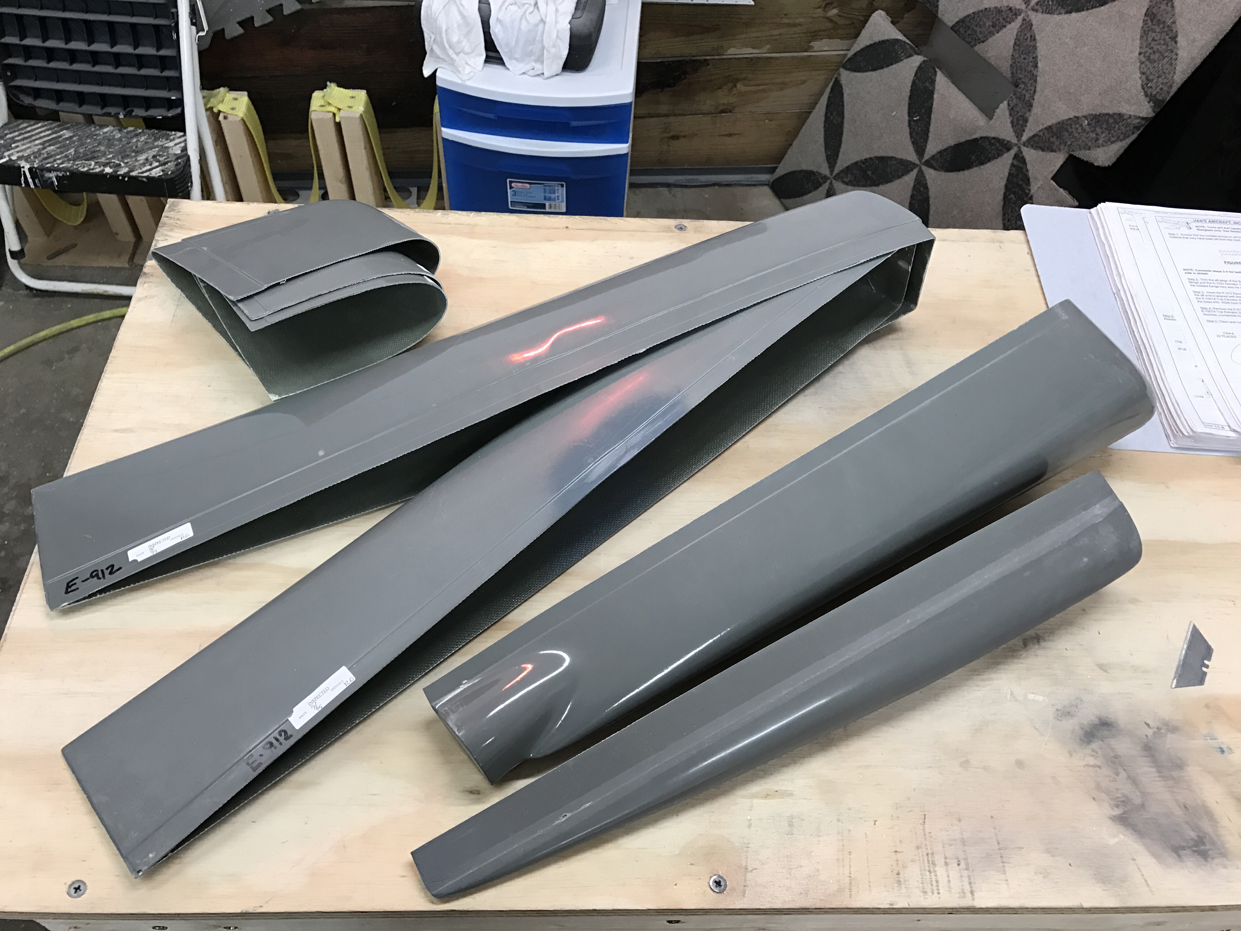
First step in this section is to fabricate two torque tubes which are used to push and pull on a bellcrank mounted on the spar. This bellcrank converts the horizontal motion into fore and aft motion to move the aileron up and down.

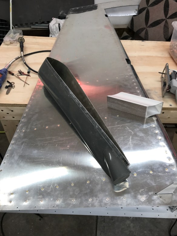
Torque tubes and end caps

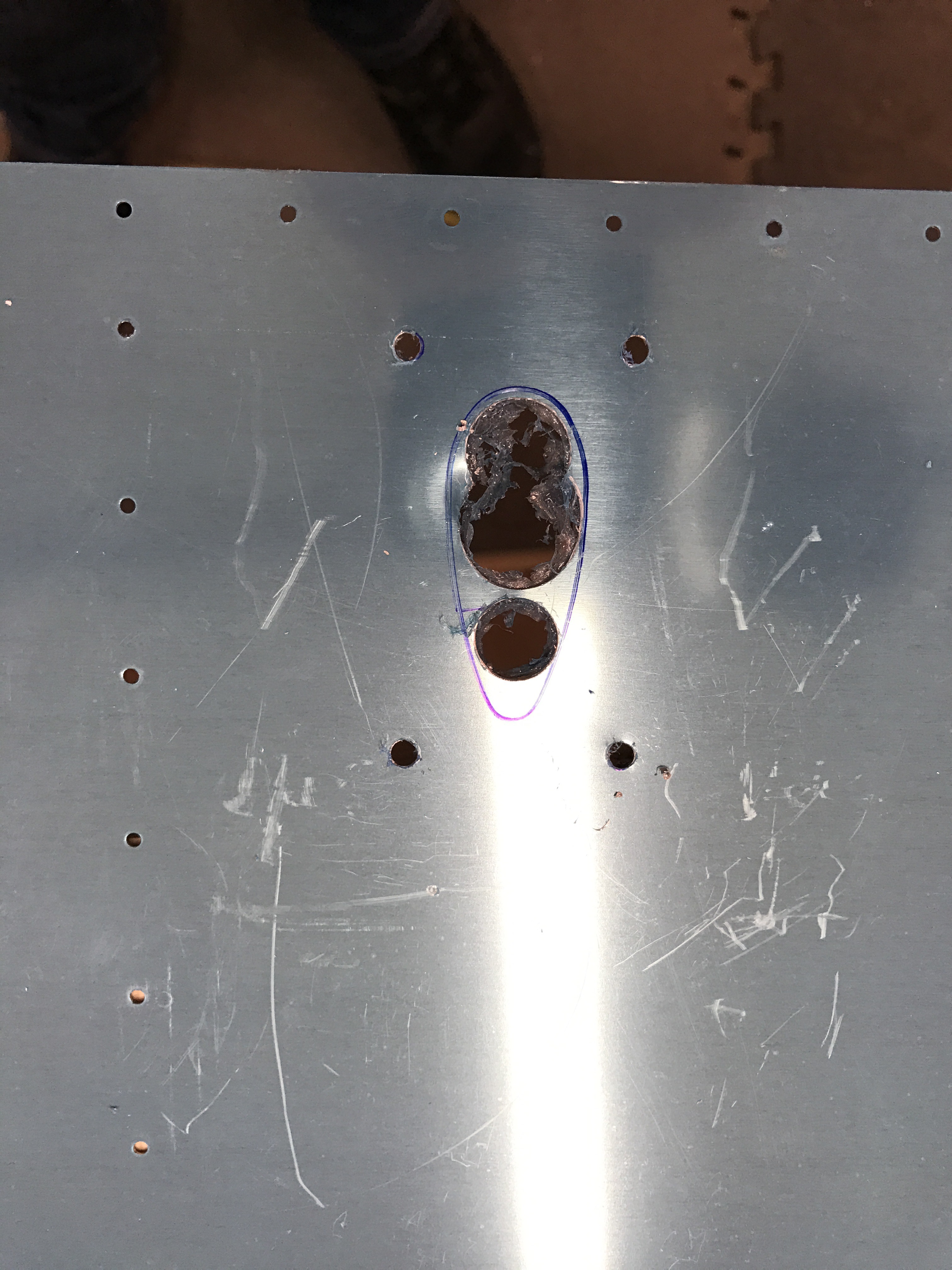
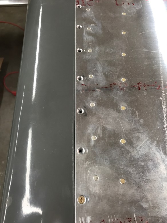
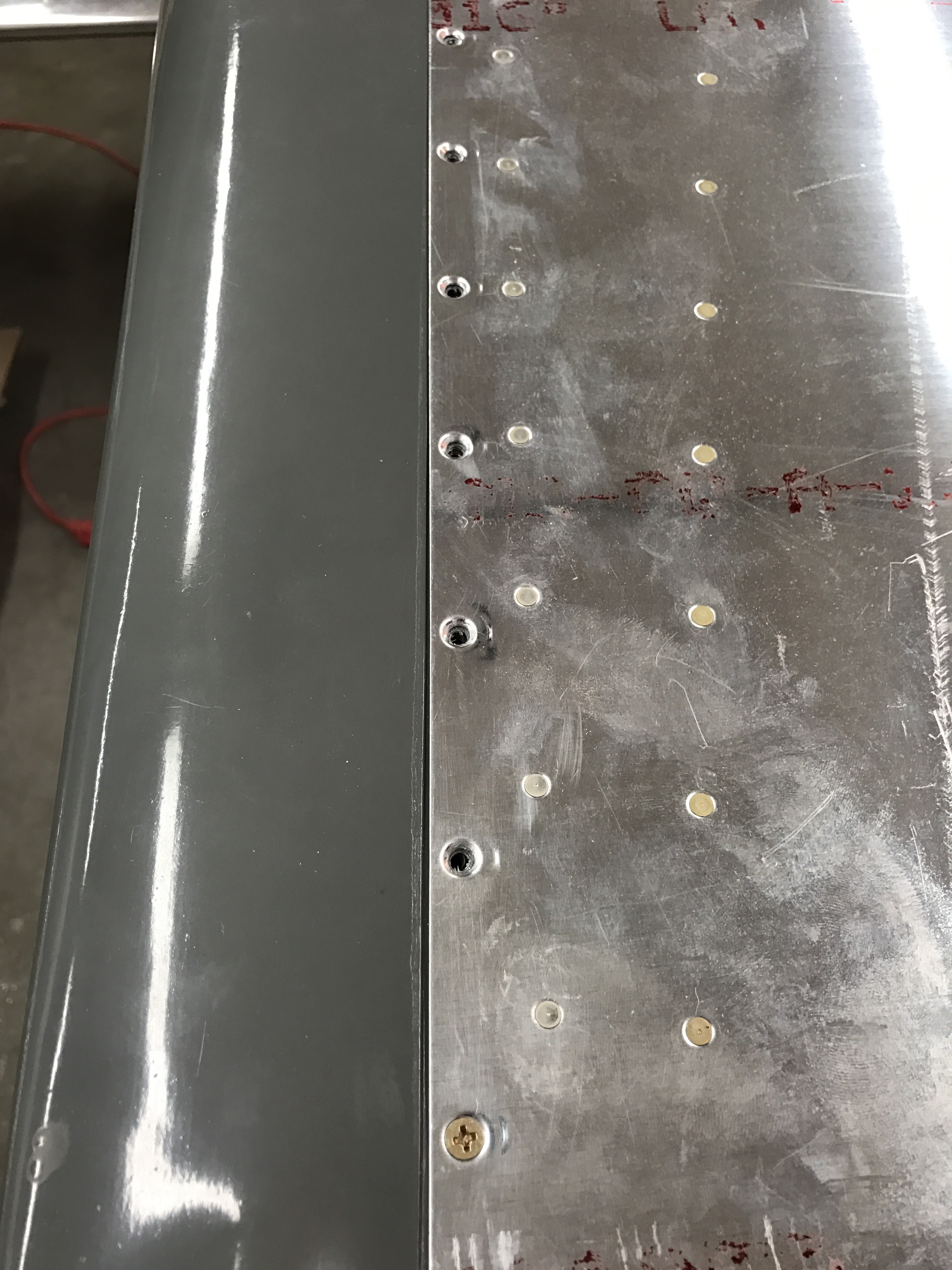
Drilling holes for the end caps
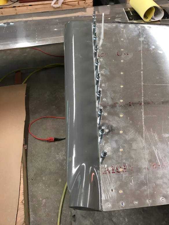
End caps riveted on

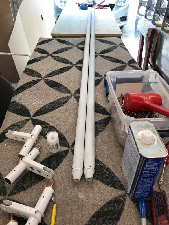
Both tubes completed and aileron torque tube ends shown too.

I then fabricated the bellcrank to aileron pushrods as well as the start of another set of aileron torque tubes which sit at the root of the wing and partly attach to bearings on the end of the gas tank. Seeing I hadn’t yet leak tested my tanks, I needed to take a break and do that, prior to reattaching them to the wings.

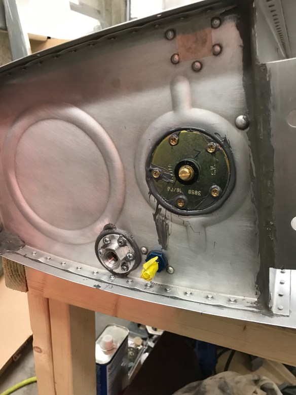
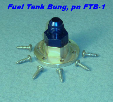
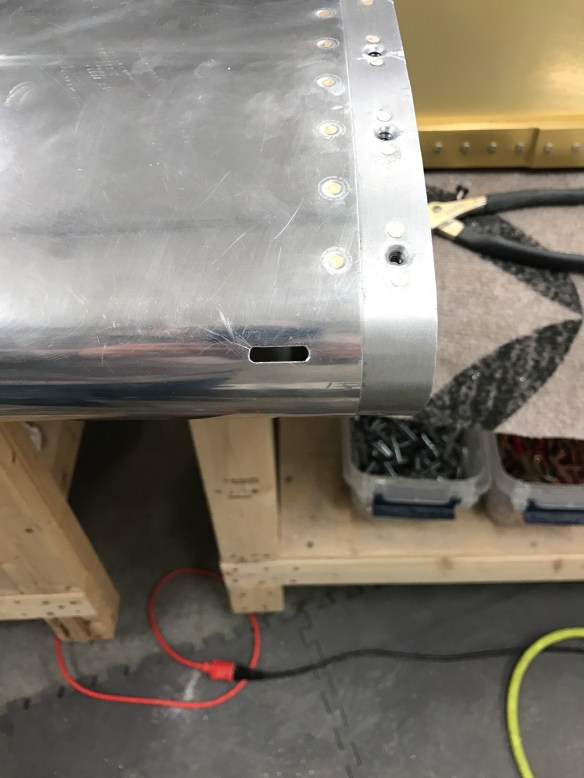
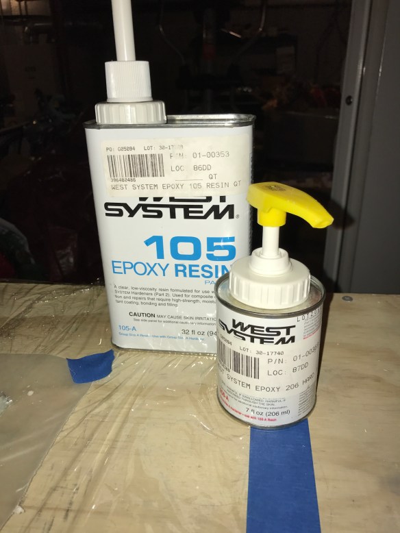
Leak testing the tanks is relatively straightforward. The idea is to seal off all openings, pressurize the tanks just enough (too much pressure can cause damage) and spray soapy water all over the seams and joints to see if there are any leaks. A bicycle pump valve is provided in the kit to go into the fuel drain port. This allows you to use a bicycle pump to inject air into the tank, pressurizing it. The fuel pickup and, in my case, fuel return line needed to be capped off. In order to provide a safety valve, a balloon is placed on the tank vent port and will inflate as you add air into the tank. The balloon acts as a safety valve and will pop prior to allowing too much pressure to be added to the tank.


Adding air to the tank

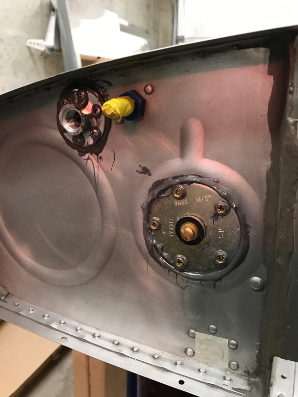
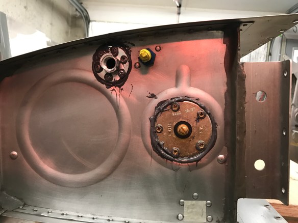
Spraying all the rivets and surfaces with soapy water

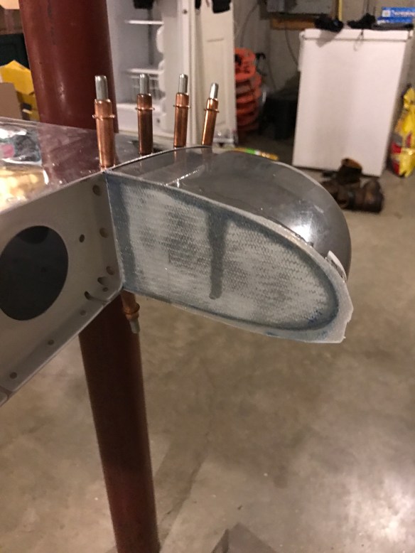
Of course, never doing this before, I wasn’t quite sure what I was supposed to see if there was indeed a leak. On the first tank I attached the balloon to the vent port with duct tape and a zip-tie. It clearly didn’t work very well and the slow leak exhibited itself by really bubbling up.


Balloon connection had a small leak. 

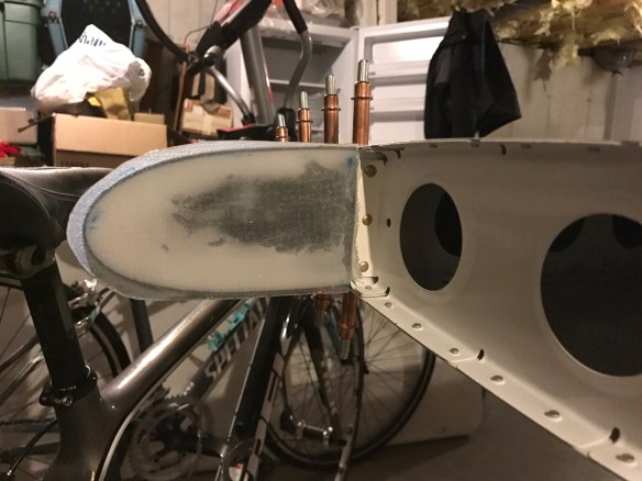
On the second attempt, I placed some fuel lube inside the neck of the balloon, used some string to ensure a better connection, along with a ziptie. That seemed to do the trick. No leaks and the balloon stayed inflated overnight.

I then was able to reattach the tanks to the wings and am relieved that the tanks didn’t have any detectable leaks in them.

With that behind me, I was able to get back to getting the aileron control system fully hooked up.

Wing root torque tube attached. Getting ready to attach the main pushrod.

Getting ready to attach the pushrod to the bellcrank

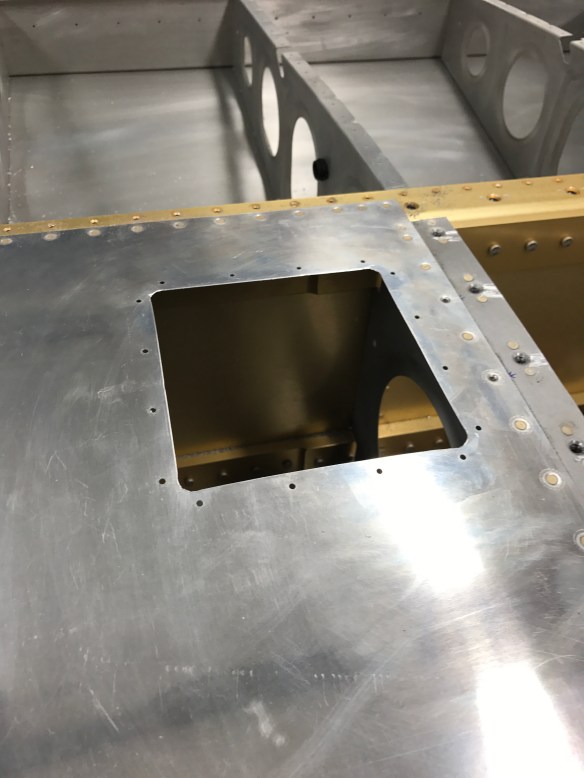
In order to properly set the length of the tube there is a jig that is inserted in the bellcrank that sets the neutral position. One must them make sure that the hole on the arm back at the wing root is exactly 2 9/32″ from the edge of the tank to the center of the hole

Setting the tube length based on the neutral position with the W-730 Jig

Exactly 2 and 9/32″ to the hole center.

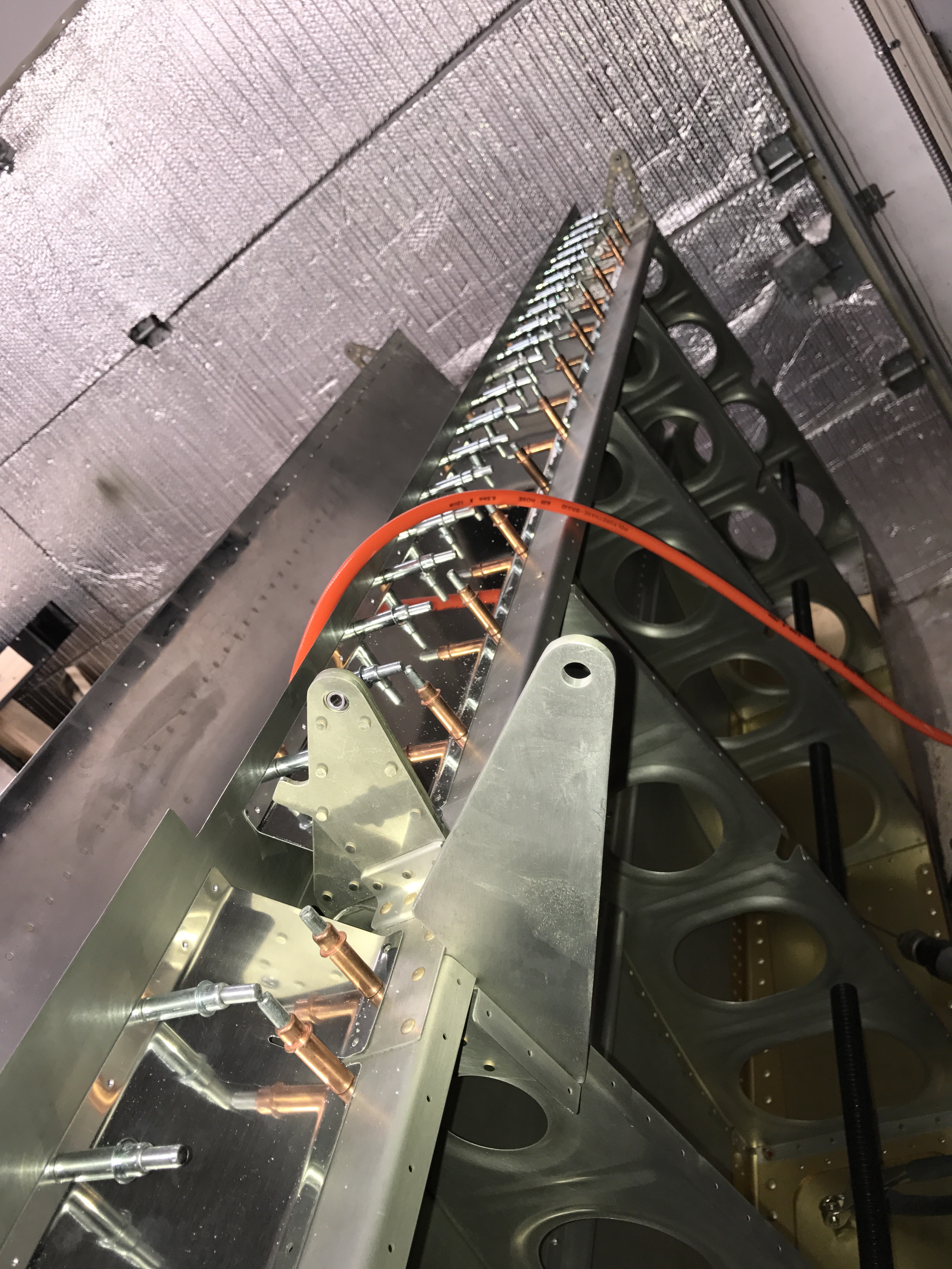
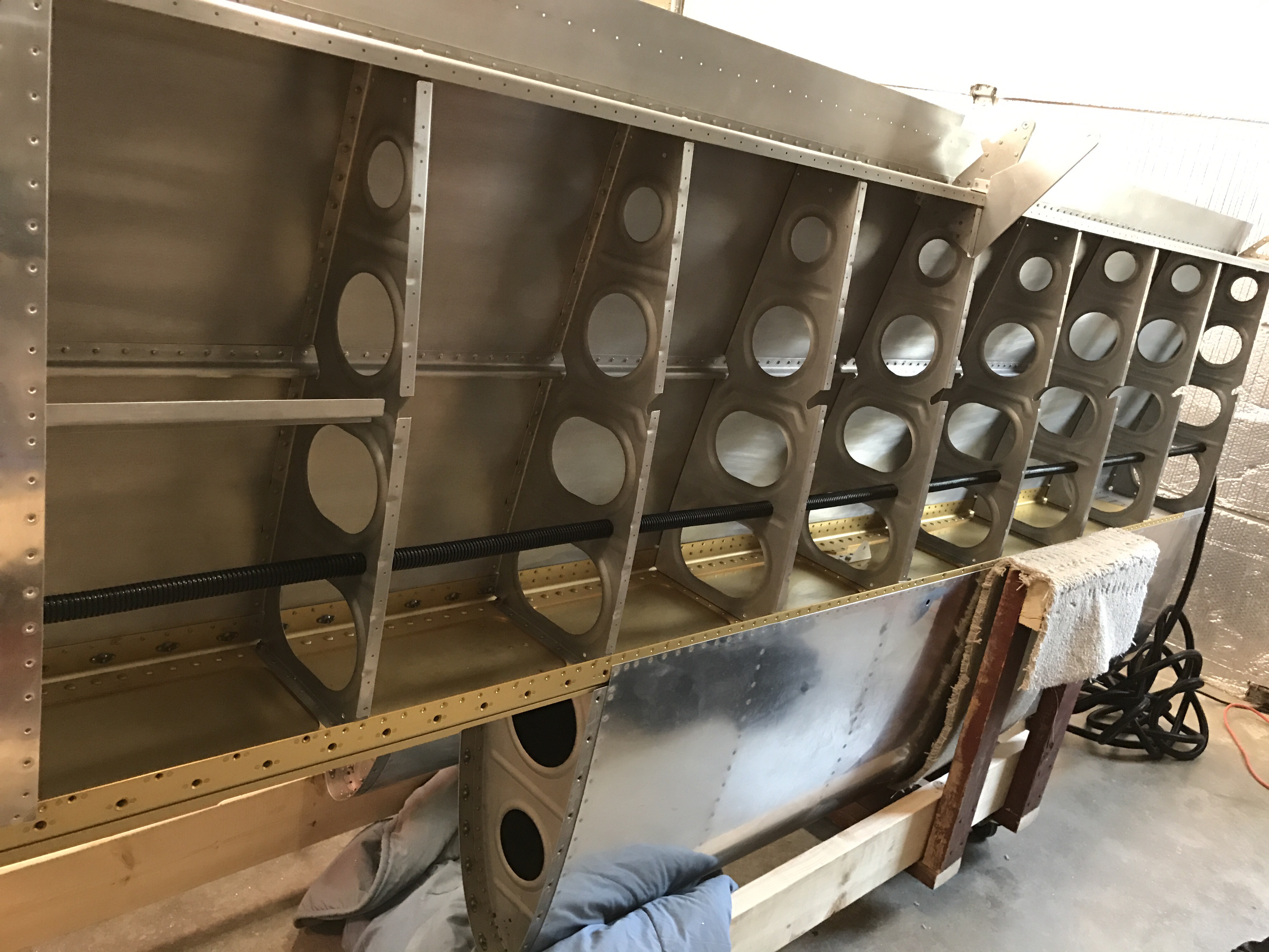
All hooked up, looking down the wing

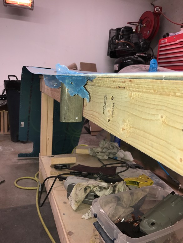
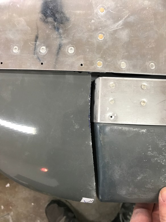
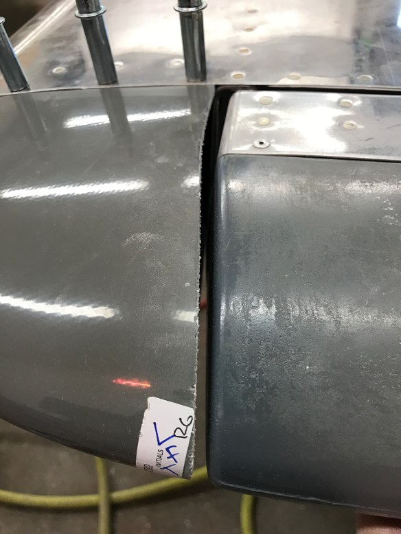
I then started getting the actual aileron and flaps placed onto the wing to set their neutral position. It is then that I discovered that I had riveted the end of the gap fairing on the wrong way. In setting up the flap position it says that the nose of the flap should sit against the spar doubler. Well instead, mine was sitting against the gap fairing, which didn’t seem correct… I went back in the plans, and sure enough, I did it wrong. Nothing that drilling out a few rivets and flipping it around can’t solve..

That 1021B-L part is not oriented the correct way. DOH!

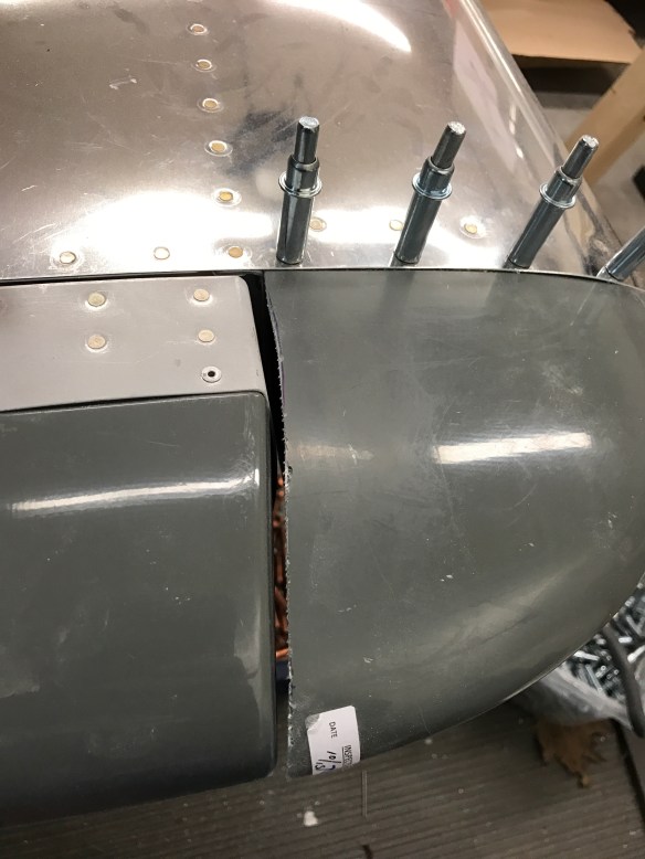
After drilling out 4 rivets and flipping it around. Much better, and makes more sense.

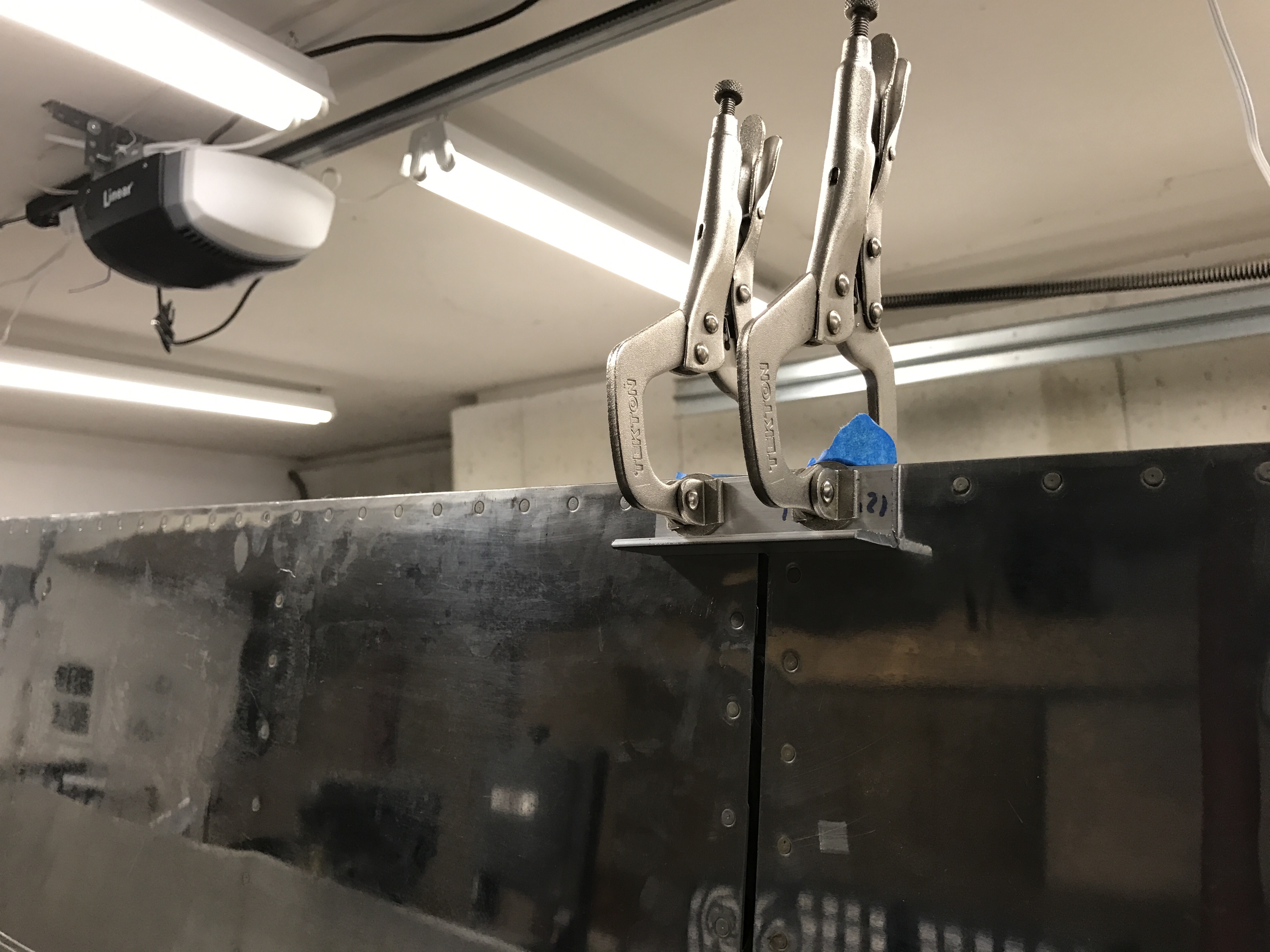
The flap is used to set the neutral position of the aileron by clamping the trailing edges together with some aluminum angle. Then with the W-730 Jig back in place to set the pushrod neutral position, the bellcrank to aileron pushrod length is adjusted so that it is perfectly fits when both items are in their neutral position.

Flap and Aileron clamped together

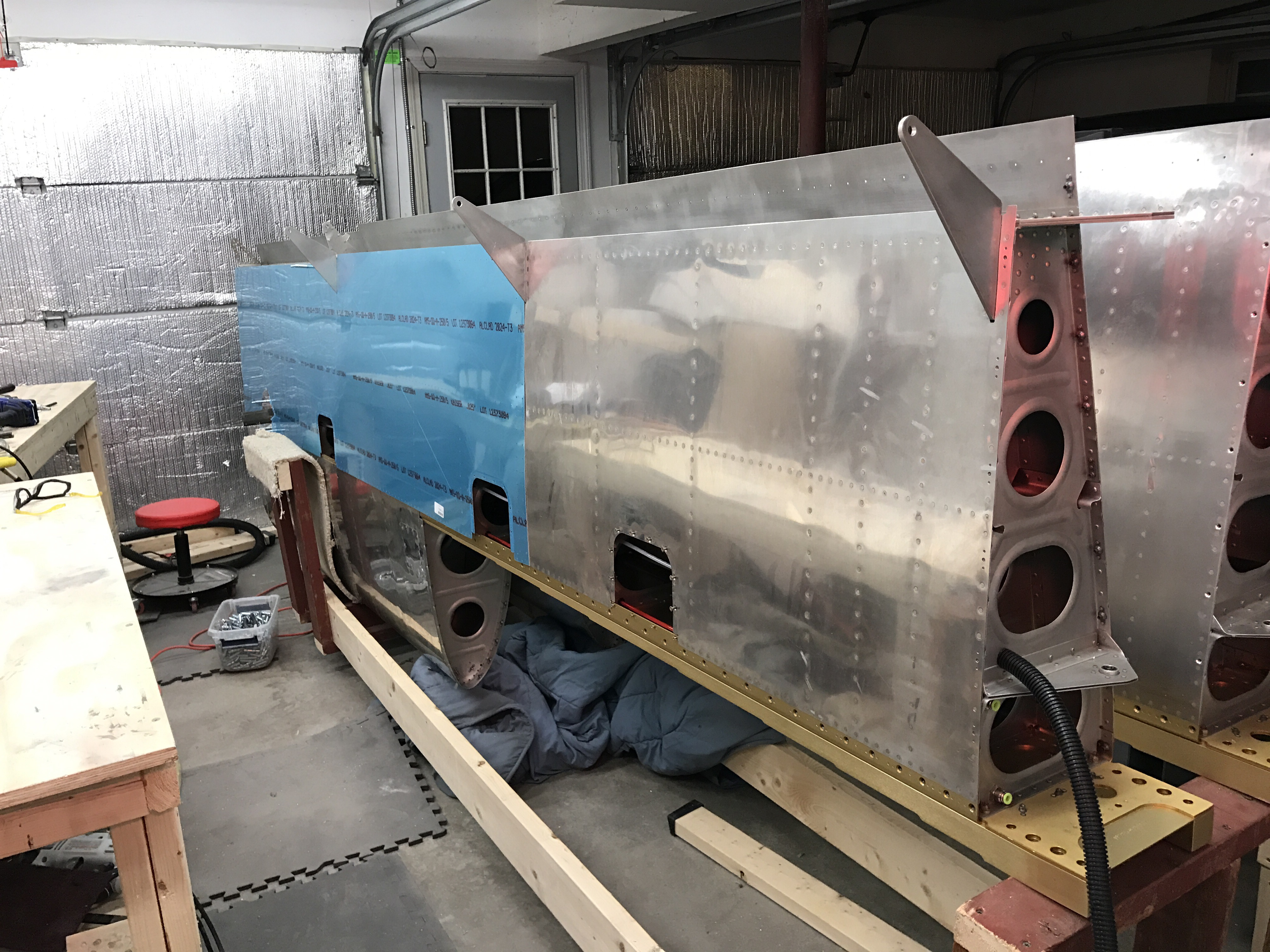
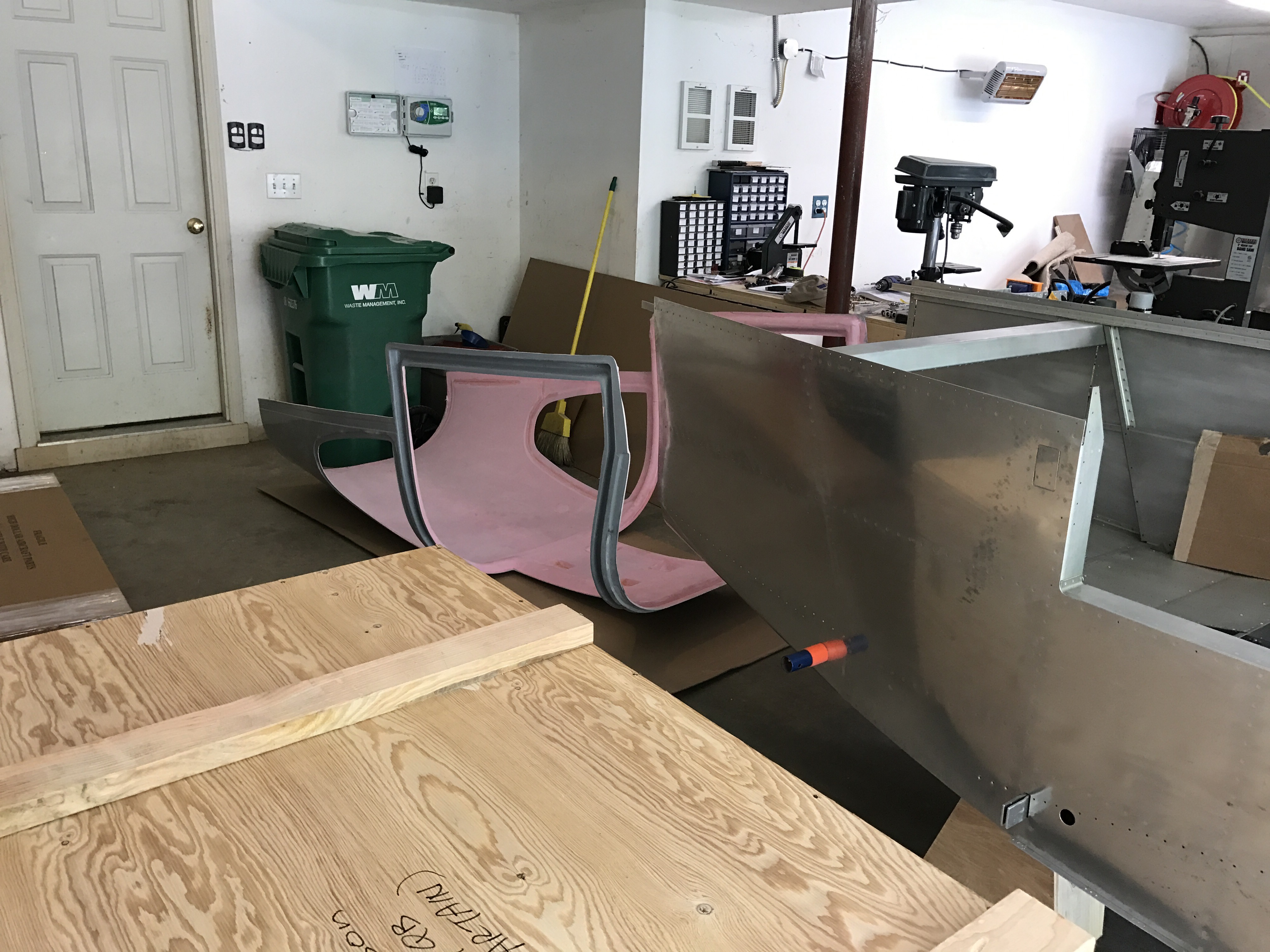
View of left wing with both flap and aileron installed

Bellcrank to aileron pushrod attached to aileron

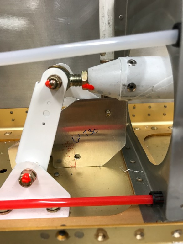
W-730 Jig back in place with bolt coming through the pushrod in the upper right of the jig meaning everything is perfectly aligned.

A view looking down at the finalized bellcrank assembly. 

Fuse and Finish kit arrive

Been a bit busy finishing some hardwood flooring in the spare bedroom as well as getting the nursery ready for our little guys arrival in early July. Plane building has suffered a little bit recently.

I’ve finished the bottom wings skins as far as I’d like for now. I’ve deburred them, but will leave the dimpling for later. I’m sure I’ll be happy to have some metal work to come back to in between all the fiberglass work coming up. I’ve started on the aileron actuation section of the plans:

I’ve fabricated the Bellcrank pushrod as well as the bellcrank to aileron pushrod and primed them. Pictures of those will be forthcoming.

In the interim, I took delivery of my Quick Build fuselage and finishing kits. These pieces account for the remaining structural pieces of the kits. All that remains after these kits are the engine (and Firewall forward kit) and the avionics. Don’t let that fool you though, there is a ton of work to do on the kits that will keep me busy for quite a long time.

Fiberglass cabin top behind the fuse

Finishing kit crate

Fuselage stand I built out of saw horses and 2×4’s with casters

Lots of stuff! Cowlings, door shells, and wheel pants. 

Continued Wing Progress

Sorry for the lack of updates recently.

Since the last update, I’ve been able to get the Pitot Tube bracket all ready to install.Like a few other RV-10 builders, I’ve decided to put my Pitot further outboard as compared to plans. I’ve placed it in the 2nd to last wing bay. This will keep it out of the way of the tie-down ring/rope and any possibility of getting it caught up.

Mounting the Pitot  involved adding a piece of aluminum angle to the outboard rib such that the bracket would sit flush with the rib flange and allow the bottom wing skin to sit flush to the rib. I also used the bracket to draw the outline of the cut needed on the bottom skin. A unibit was used to cut the initial holes and then files were used to shape and debur the cut.

Making sure the bracket sits flush to the rib flange

Aluminum Angle support riveted to the rib

Using the bracket to drill the bottom skin.

All Filed clean

Testing the Pitot Mount fit through the bottom skin cut

Pitot Mast in rough place with the bottom wing skin on.

All the holes are now match drilled.

I then moved on to continue the bottom skin section of the plans.

I will finish this section up until the point of actually riveting the bottom skins in place. I plan to do that at a much later date. While things like auto-pilot servos and wiring can be done after the fact, it’ll be much better to allow access for these tasks later on.

The first part after dealing with the pitot tube, was to match drill and rivet on the gap fairings for the aileron and flaps. Below they are shown cleco’ed in place. I’ve already riveted them, but apparently didn’t take any pictures of them finished.

I’ve also got the J-channel stiffeners all in place and match drilled to the bottom skins. The bottom skins are also match drilled to the ribs and spars. All that is left for this section is to debur everything and dimple all the holes.

Wing Update

Next up was to knock off fuel tank related items so I could get to a spot where I could proseal the fuel senders and the fuel return ports onto the tank.

First I had to bend the sender rod as shown in the plans. 

Then I needed to test out the sender to make sure it can go stop-to-stop without hitting anything inside the tank. Mostly the fuel vent line is what typically gets in the way. I measured the resistance at the stops on the bench to know what values I should see. I then used a string down through the drain opening to help me pull the float up and down in the tank. I had to bend the float towards the front of the tank to get it to not hit the vent line. After a couple of iterations, I declared success.

I then started on the fuel return port. The EFII instructions only require that you place the fuel return at least 3 inches away from the feed line to prevent bubbles from fuel being returned to the tank from being picked up and sent back into the feed line. After reviewing some posts on VAF, and seeing multiple other people put their fuel return lines in a spot that would interfere with attaching the tank and the wing to the main spar, I decided the best spot was just forward of the vent line port. Several others ended up with similar placement. Once the spot was decided, I had to drill a 0.5″ hole for the center AN fitting and surrounding holes for the screws which help prevent rotation of the bung.

img_8731img_8730img_8732img_8734

I’ll let this sit for a while to cure, then it’ll be time to leak test the tank.

I was also able to enlarge the holes in the wing ribs to 3/4″ to accept conduit for my wire runs. I also added a second 7/16″ hole to run a second static line to my Pitot tube for its AOA function.

Garmin GAP26 Heated Pitot Tube and Mount


Static lines and conduit routed 

Wing Progress…

Even with Quick Build wings, the instructions tell you to go over everything step-by-step to make sure everything was completed. This was the discrepancy list I came up with after my review:

Of course some of the complete sections that have yet to be done, are expected. The following shows the sections that a Quick builder has to complete. (All the shaded sections)

2017-02-19-20_50_26-plans-google-drive

I started knocking off some of the list above by tapping the tie-down blocks, and installing the nutplates on the inboard edges of the wings, also removing the fuel tanks and riveting on the bearings to the attachment bracket. I seem to be jumping around a bit based on what makes sense next.

I’m currently thinking strongly about utilizing both Electronic Ignitions and Electronic Fuel injection systems in the plane. The electronic fuel injection requires fuel to circulate back to the tanks, requiring me to add a fuel return fitting to my already completed tanks. I ordered these “bungs” from EFII which make adding a port like this relatively straight forward. If I don’t end up going that way, these will be easy to cap off.

 return_fuel_fitting1

While waiting for these and some proseal to come in, I started working on section 19; The Stall warning system.

The Stiffener acts as a template

It’s really tough to drill and cut through a perfectly good skin.

4 corner holes with cutout outline

Access Panel cut complete

Stiffener with nutplates installed.

Holes drilled and rough cut of the slot for the stall warning vane

Tech Councilor Visit #2

Last weekend, my tech councilor came over for a visit to look over my work since his first visit. He reviewed the elevators and the tailcone construction. He also quickly looked over the rework that I did to the VS and Rudder after his suggestions. I was very happy that he only had good things to say! Always reassuring to hear that, and I’m very happy to have a more experienced eye look over everything.

We Have Wings!

My Quick build wings were ready to ship about mid-way though January. I decided to use Partain Trading Company for shipping. These guys specialize in hauling these Quick Build kits. The Kit goes into the truck and doesn’t leave the truck until it gets to its destination. Because of this, there is no need to crate the wings, and the $400 crating charge vanishes. I believe that possible damage to things is greatly minimized, probably as close to zero chance as you can get. There’s no on and off multiple trucks and forklifts as it makes its way across the country via normal freight. Also the drivers are very willing to help out with getting the kit to its final destination, my garage! The only downsides are they make trips every couple of weeks, so my wings weren’t picked up at Van’s until the end of January. So there’s a little delay in getting the kit, but seemed well worth it to me. The communications with the trucking company (actually the driver) was excellent. There were some additional delays due to the crane breaking and some bad weather (we got about 14″ of snow on my original scheduled delivery day). The driver kept in touch on a daily basis to let me know what was going on, and today (Saturday morning) my wings were delivered, despite getting an additional 1-2″ of snow overnight, snow continuing throughout the delivery, and the roads weren’t all that great out for a tractor trailer lightly loaded.

I was able to inventory everything today and should be ready  to get going on looking over the wings more carefully against the plans tomorrow after my 2nd tech councilor meeting in the morning. Some pics of my delivery today!

img_8402

Aileron

Flap

img_8409

Aileron and Flap Placed on one wing

My Quickbuild Fuselage is due to be shipped in the May timeframe, so I have a few months to get the wings finished up.

In other news: Last night my wife and I found out that we are having a baby boy in July. I’m sure I won’t have nearly the same amount of free time after that point. That is the leading reason for deciding to go the quick build route on both wings and fuselage. I’ll need all the acceleration I can get if I want to finish this thing anytime in the not so distant future!

Fairings Complete

Some quick pics of how the rest of the fairings came out..


HS Closeout piece curing

Layer of Flox on the inside corner

Curing

VS Fairing prep.. Taping the closeout piece in place

VS piece done!

Riveting onto VS.

I then built a wing stand for my Quick Build Wings arriving soon….

Done minus the carpet.

Learning about Fiberglass

I’ve been doing a lot of reading and watching videos on fiberglass related things. Everything from what the best tools are to use to proper fiberglass layup techniques.

Trimming and cutting the Elevator fairings ended up spewing lots of dust all over the place… I then bought a diamond cutting wheel for my Dremel tool and also bought some PermaGrit tools, which are made of tungsten carbide materials and do a better job of making sawdust like shavings instead of dust. Seeing there is so much fiberglass work coming, I figured I’d invest in some proper tools for this work that’ll be upcoming.

I bought some sanding blocks, both flat and concave.

wb140

As well as a hand tool set and blades for my jig saw.

I then set out to finish the rudder end caps. Fairly straight forward. The only modification I did was to add nut plates to the bottom fairing to accept #6 screws to make the fairing removable. Many RV-10 builders do this mod, and it didn’t really take all that much extra effort.

Top fairing trimmed, drilled #40, and cleco’ed in place

Sanding the bottom fairing to fit

Bottom fairing cleco’ed in place

Rudder Fairings Complete.

Then it was time to figure out the Horizontal Fairings. These sit in front of the elevator counterbalance arms and elevator tips. The tips seem to taper off a bit and are not straight. So I decided pretty early to trim the HS fairings to match.

I traced the leading edge of the counterbalance arm and fairing on a piece of paper to get a template to use to mark my cuts to the trailing edge of the HS fairing. This worked pretty well. I then was able to sand to make the gap as even and consistent as I could.

Left side test fit

Left side Gap.

Right Side Gap

Next, the plans describe how to add a fiberglass layup to close out the aft ends of the fairings. I read an alternate method on VAF by one of the VAN’s employees that is detailed in the RV-14 plans which doesn’t involve trying to shape and tack a piece of foam into each opening.

– Use a piece of waxed aluminum to make a thin laminate with two layers of cloth and resin. If the close out piece is not flat, the metal can be bent/shaped to result in a laminate piece that will match the opening you are intending to seal.

– Once it is cured cut out the filler piece so that it is approx. 1/6″ bigger around perimeter of the fairing opening.

– Sand the interior (non smooth) surface of the lay-up, and about 1″ back from the edge of the fairing for additional bonding/glass lay-up later.

-With the fairing clecoed in place and tape/etc. being used to hold it in the desired finished shape, wet the edge of the fairing with resin… and hold the laminate in place with tape to the fairing until the resin fully cures.

-Uncleco and remove the fairing. Apply a fillet of flox mixture around the interior corner/intersection point between the laminate and the fairing. While the flox is still wet, add one more layer of glass to the inside of the laminate, large enough that it laps onto the fairing by about 1″. Cleco the fairing back onto the airframe while it fully cures.

– Sand the excess laminate flush to the fairing on the outside and radius the corner as desired (possible because of the flox fillet on the inside).

As mentioned above, seeing my ends to close out are not flat from me shaping them to the Elevator fairings, I cut some scrap metal (one piece for each fairing) and bent/shaped it to match each one. This will provide the base for my fiberglass layup that should hopefully match the cut line I made. Time will tell.

My first 2 ply layup

Prepping to start the right side

The Resin Epoxy and hardener I’m using

Both layups done and ready to cure.

Section 12 – Fiberglass Fairings

Today I started on the fiberglass fairings for the ends of all surfaces. For the most part, these all come pre-formed. Some trimming and drilling are all that is needed to fit them to the airplane. There are a couple of fairings that will need to have an end closed up with a fiberglass layup. So I’ve ordered some supplies to do that. I ordered some West Systems 105 resin epoxy with hardener, along with some flox, microballons, and some fiberglass cloth to get me started. I also ordered the fiberglass practice kit from Aircraft Spruce with a book to play around a bit honing my skills. I’ve never really worked on fiberglass before, so this will be all new to me.

Fairings!

Fitting the fairing to the left Elevator

Riveted on!

Front angle

 More of this to come!